EP1918469A2 - Système de raccordement d'isolation thermique - Google Patents
Système de raccordement d'isolation thermique Download PDFInfo
- Publication number
- EP1918469A2 EP1918469A2 EP07020665A EP07020665A EP1918469A2 EP 1918469 A2 EP1918469 A2 EP 1918469A2 EP 07020665 A EP07020665 A EP 07020665A EP 07020665 A EP07020665 A EP 07020665A EP 1918469 A2 EP1918469 A2 EP 1918469A2
- Authority
- EP
- European Patent Office
- Prior art keywords
- thermal insulation
- composite system
- locking element
- insulating
- insulation composite
- Prior art date
- Legal status (The legal status is an assumption and is not a legal conclusion. Google has not performed a legal analysis and makes no representation as to the accuracy of the status listed.)
- Granted
Links
- 238000009413 insulation Methods 0.000 title claims abstract description 171
- 239000002131 composite material Substances 0.000 title claims abstract description 51
- 230000015572 biosynthetic process Effects 0.000 claims abstract description 9
- 230000000295 complement effect Effects 0.000 claims abstract description 8
- 238000000034 method Methods 0.000 claims abstract description 7
- 239000006260 foam Substances 0.000 claims description 11
- 239000000463 material Substances 0.000 claims description 7
- 239000000853 adhesive Substances 0.000 claims description 6
- 230000001070 adhesive effect Effects 0.000 claims description 6
- 238000000926 separation method Methods 0.000 claims description 2
- 210000001503 joint Anatomy 0.000 claims 1
- 239000011810 insulating material Substances 0.000 description 7
- 239000012790 adhesive layer Substances 0.000 description 5
- 238000004519 manufacturing process Methods 0.000 description 5
- 239000002557 mineral fiber Substances 0.000 description 5
- 238000010276 construction Methods 0.000 description 4
- 238000005520 cutting process Methods 0.000 description 4
- 239000004793 Polystyrene Substances 0.000 description 2
- 239000012774 insulation material Substances 0.000 description 2
- 238000005304 joining Methods 0.000 description 2
- 239000011505 plaster Substances 0.000 description 2
- 229920002223 polystyrene Polymers 0.000 description 2
- KXGFMDJXCMQABM-UHFFFAOYSA-N 2-methoxy-6-methylphenol Chemical compound [CH]OC1=CC=CC([CH])=C1O KXGFMDJXCMQABM-UHFFFAOYSA-N 0.000 description 1
- 244000198134 Agave sisalana Species 0.000 description 1
- 244000025254 Cannabis sativa Species 0.000 description 1
- 235000012766 Cannabis sativa ssp. sativa var. sativa Nutrition 0.000 description 1
- 235000012765 Cannabis sativa ssp. sativa var. spontanea Nutrition 0.000 description 1
- 238000004026 adhesive bonding Methods 0.000 description 1
- 239000011230 binding agent Substances 0.000 description 1
- 235000009120 camo Nutrition 0.000 description 1
- 235000005607 chanvre indien Nutrition 0.000 description 1
- 239000007799 cork Substances 0.000 description 1
- 238000005553 drilling Methods 0.000 description 1
- 230000000694 effects Effects 0.000 description 1
- 239000000835 fiber Substances 0.000 description 1
- 239000011487 hemp Substances 0.000 description 1
- 238000009434 installation Methods 0.000 description 1
- 239000010410 layer Substances 0.000 description 1
- 239000004570 mortar (masonry) Substances 0.000 description 1
- 239000005011 phenolic resin Substances 0.000 description 1
- 229920001568 phenolic resin Polymers 0.000 description 1
- 239000004033 plastic Substances 0.000 description 1
- 229920003023 plastic Polymers 0.000 description 1
- 239000010902 straw Substances 0.000 description 1
- 238000009966 trimming Methods 0.000 description 1
Images
Classifications
-
- E—FIXED CONSTRUCTIONS
- E04—BUILDING
- E04B—GENERAL BUILDING CONSTRUCTIONS; WALLS, e.g. PARTITIONS; ROOFS; FLOORS; CEILINGS; INSULATION OR OTHER PROTECTION OF BUILDINGS
- E04B1/00—Constructions in general; Structures which are not restricted either to walls, e.g. partitions, or floors or ceilings or roofs
- E04B1/62—Insulation or other protection; Elements or use of specified material therefor
- E04B1/74—Heat, sound or noise insulation, absorption, or reflection; Other building methods affording favourable thermal or acoustical conditions, e.g. accumulating of heat within walls
- E04B1/76—Heat, sound or noise insulation, absorption, or reflection; Other building methods affording favourable thermal or acoustical conditions, e.g. accumulating of heat within walls specifically with respect to heat only
- E04B1/762—Exterior insulation of exterior walls
-
- E—FIXED CONSTRUCTIONS
- E04—BUILDING
- E04B—GENERAL BUILDING CONSTRUCTIONS; WALLS, e.g. PARTITIONS; ROOFS; FLOORS; CEILINGS; INSULATION OR OTHER PROTECTION OF BUILDINGS
- E04B1/00—Constructions in general; Structures which are not restricted either to walls, e.g. partitions, or floors or ceilings or roofs
- E04B1/62—Insulation or other protection; Elements or use of specified material therefor
- E04B1/74—Heat, sound or noise insulation, absorption, or reflection; Other building methods affording favourable thermal or acoustical conditions, e.g. accumulating of heat within walls
- E04B1/76—Heat, sound or noise insulation, absorption, or reflection; Other building methods affording favourable thermal or acoustical conditions, e.g. accumulating of heat within walls specifically with respect to heat only
- E04B1/78—Heat insulating elements
- E04B1/80—Heat insulating elements slab-shaped
Definitions
- the invention relates to a thermal insulation composite system, in particular a thermal insulation composite system with mineral fiber insulation boards, and a method for training the same.
- Thermal insulation systems with rigid foam insulation boards or mineral fiber insulation boards with horizontal or vertical fibers are usually glued on the building wall and possibly additionally pegged.
- thermal insulation systems for example for passive houses, are designed with very thick insulation boards.
- open joints between the insulation boards are created by tilting, if they are not aligned exactly plane-parallel.
- joints between the insulation boards can reduce the thermal insulation.
- the joints must be additionally sealed or it must be provided a joint-free training by careful alignment of the insulation boards. This creates high additional workload.
- Object of the present invention is to provide a thermal insulation composite system that is easy and safe to lay and is inexpensive.
- the object of the invention is achieved by a composite thermal insulation system with arranged on a building wall in horizontal rows, preferably cuboid insulation boards, each adjoining each other at lateral end faces and fixed to the building wall facing the rear side surface by means of adhesive and possibly additional dowels on the building wall, wherein it is provided that adjoining insulating panels of a series of mutually facing end faces each have a groove and the grooves are formed so that the grooves overlap facing end faces and form in their overlap space a receiving area in which a cross-sectional complementary to the receiving area formed locking element is arranged.
- the object is further achieved with a method for forming a thermal insulation composite system with arranged on a building wall in horizontal rows plate-shaped insulation boards with rectangular front surface, which are fixed by means of adhesive and possibly additional dowels on the building wall, it being provided that on the lateral end faces adjacent insulation boards and at the upper end side of the insulation board locking elements are inserted in trained in these end faces grooves that a first row joint-to-joint bonded insulation boards glued to the building wall and / or will work, and that the first row of insulation boards a second row Insulating boards shock-to-shock is placed on the building wall so that the arranged in grooves on the upper face of the insulating board of the first row locking elements engage in the grooves on the lower face of the second row insulation board, the insulation boards with the building wall glued and possibly additionally pegged.
- thermal insulation composite system combines functional advantages with technological advantages. Due to the virtually seamless design of the thermal insulation composite system, for example, thermal bridges are avoided, which can be formed by introduced in joints adhesive or mortar or by floor extensions in the case of tilting the insulation boards. The introduction of the locking elements saves compared to the grouting working time, increases the processing safety and is also executable by less qualified personnel quality.
- Another advantage is that the grooves introduced into the insulation boards facilitate the handling of the large-sized insulation boards on the construction site, for example, by the grooves are used as gripping surfaces.
- the locking element is formed in a form-fitting manner in cross section to the overlapping space.
- the locking element extends in its longitudinal extent over the entire longitudinal extension of the receiving space. Still further advantageously, it can be provided that the locking element extends in its longitudinal extent over the longitudinal extent or over the height extent of a plurality of insulating panels or at least exceeds the longitudinal extension or the vertical extent of an insulating panel. In this way, adjacent insulation boards can be as it were interlocked with each other.
- the groove is rectangular in cross-section.
- the groove is rounded in cross section, preferably semi-circular.
- the cross section of the locking element may be formed corresponding thereto. But it can also be provided to form the locking element with a deviating from the cross section of the groove cross-section. For example, it may be provided to provide the surfaces of the locking element which run parallel to the joining direction with teeth which are directed so that they rest on joining and on opposite sides Erect stress and wed in the groove.
- the groove in the front side extends longitudinally in a vertical plane or in a horizontal plane.
- the groove may extend over the entire longitudinal extent or the entire width extent of the end face.
- the groove is formed in the lateral vertical end face.
- the groove may also be formed in the lower or upper horizontal end face.
- the groove is formed as a circumferential groove of the insulation board.
- the grooves forming the receiving space each have the same cross section.
- the grooves forming the receiving space each have the same longitudinal extension.
- the locking element is designed as an elongate body, preferably as a rod, longitudinal profile or the like.
- the locking element may also be referred to as a so-called false spring, as provided in a special embodiment of the tongue and groove connection.
- the locking element is designed as a plate-shaped body.
- the locking element is designed as a cut-to-length body.
- the receiving spaces of a plurality of arranged in a horizontal row insulation panels or more vertically stacked insulation panels form a composite receiving space and extending the locking element or more successively arranged locking elements over the entire longitudinal extent of the composite receiving space or extend.
- the length of the bolt elements is dimensioned so that the receiving space is completely filled.
- the vertical bar elements i. the locking elements, which are arranged in the receiving spaces formed by the grooves of the lateral end faces, are arranged as a continuous strand, then it can be provided to cut off the horizontally extending locking elements in each case to the clear distance between two adjacent strands.
- it can be provided to cut off the vertically extending locking elements in each case on the clear distance between two horizontally extending strands, wherein the horizontally extending locking elements are arranged as a continuous strand.
- the locking elements can also be provided to form the locking elements in two lengths, wherein the first length of the width or the height of the insulating board corresponds and the second length corresponds to the height or the width of the insulating board minus the groove depth.
- angularly formed insulation boards are arranged with circumferential groove, wherein the angle between the two legs of the insulation board corresponds to the angle of the building corner.
- the angle between the two legs of the insulation board is 90 °.
- Such an L-shaped insulation board can be used both for thermal insulation of outside corners and inside corners.
- a first and a second insulating board are arranged angularly, wherein the rear or front edge portion of the front surface of the first insulating board, which is engaged with the adjacent end side of the second insulating board via the locking element, a has complementary groove to the adjacent groove of the second insulation board.
- Any corner angle can be set, i. pointed, dull and dull corner angles. It may be provided to dispense with the formation of grooves in non-rectangular corner areas and to add the two insulation boards in the corner jointless to each other to avoid the production cost of introducing oblique grooves.
- the locking element preferably in the corner region with a circular cross section, as stated above, and the grooves with a semicircular cross section.
- This can result in technological advantages, in particular when trimming the insulation panels required for the corner area on the construction site.
- it can be provided to produce the two insulation panels required in the corner area from an insulation board.
- a central through hole with the diameter of the circular cylindrical locking element is introduced into the insulation board, which is directed parallel to the two front sides of the upper end side to the lower end side, and that then a separating cut is introduced, wherein the cutting plane with the front sides includes half the corner angle and perpendicular to the upper or lower end side of the insulation board directed through the hole axis.
- each of the insulating panels has a circumferential groove which is introduced into the end faces. If such an insulation board is cut to length, then at least one end face of the cut insulation board no longer has a groove or it has a groove which is reduced in depth. If the introduction of the groove is preferably provided during the plate production, can be further provided to produce half and quarter plates or plates in a different denomination and provided with circumferential groove to cover on the site without rework almost any lengths can.
- the cutting to length of the insulating board can also be provided for the plate height, for example, to be able to adapt the last row of insulating boards to the dimensions of the building wall.
- the insulation board has a plate format of about 1000 mm x 500 mm. But it can also be provided smaller or larger plate dimensions, without departing from the inventive principle.
- the insulation board has a thickness ⁇ 150 mm.
- the insulation board is designed as a rigid foam insulation board.
- the rigid foam may preferably be polystyrene rigid foam. It can also be provided other foamed plastics, such as Poyurethan or phenolic resin. But it can also be provided to form the insulation board of inorganic insulating material, such as mineral fibers or organic insulation material, such as sisal, hemp, straw or cork. It may be provided if necessary, the introduced into the insulation board grooves by a binder form stable.
- the locking element is formed of the same material as the insulating board.
- the locking element is formed of a different material than the insulation board.
- the locking element has a lower thermal conductivity than the insulating board.
- the locking element is designed as a rigid foam element.
- other insulating materials may be provided, as described above for the insulation board.
- a groove complementary to the groove in the end face of the second insulating plate is introduced.
- the insulation boards provided for covering the corner of the building are produced by halving an insulation board, it being provided that a central through hole is made in the insulation board for forming the two grooves required in the corner area, which runs parallel to the two front sides of the upper end face is directed to the lower end side, that then a separating cut is introduced into the insulating board, wherein the cutting plane perpendicular to the upper or the lower end side of the insulating board directed through the center axis of the through hole and with the front sides of the insulating board half corner angle the building corner includes that the obtained from the insulation board half insulation boards are applied shock-to-joint on the building corner, with one half of the insulation boards is applied rotated by 180 ° with respect to the other half insulation board, and that in the circular cylindrical receiving space formed by the two semicircular grooves of the half insulation boards a circular cylindrical locking element is introduced.
- this method the effort required for the processing of an insulating board on the construction site can be considerably reduced. It is particularly advantageous that only one
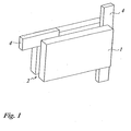
- Fig. 1 shows an insulating panel 1 of the thermal insulation composite system according to the invention.
- the insulation board 1 is formed as a rectangular flat body and has in the illustrated embodiment, a front dimension of 1000 mm x 500 mm, and a plate thickness of 300 mm. It may preferably be formed as rigid foam insulation board.
- the rigid foam may preferably be made of polystyrene rigid foam. But it may also be an insulation board made of mineral fibers or other insulating material.
- the insulation board 1 has at each of its end faces a groove 2, which is rectangular in cross-section, so that the grooves 2 form a circumferential groove.
- the insulating panels 1 are arranged in horizontal rows, butt-to-joint, on a building wall 5, i. they are arranged without forming a joint.
- the opposing grooves overlap mutually facing end faces and form in their overlap space a receiving space for a locking element 4.
- the cross section of the locking element 4 is dimensioned so that it completely fills the overlap space of the two adjacent grooves 2.
- the overlap space thus forms a complementary to the locking element 4 formed receiving space in which the locking element 4 is received positively.
- the positive connection formed by the locking element 4 could also be referred to as tongue and groove connection, wherein the locking element 4 can be referred to as a "false spring".
- the locking element 4 can be arranged on alien end faces of the insulation board 1 and thereby connect the insulation board 1 with both horizontally adjacent and with vertically adjacent further insulating plates form-fitting manner.
- the locking element 4 may be formed from the same insulating material as the insulation board 1, so for example made of rigid foam or mineral fiber insulation. But it can also be provided for a different insulating material to the insulating board 1, preferably an insulating material whose thermal insulation is higher than the thermal insulation of the board insulation material. In this way, thermal bridges are avoided particularly well, which can reduce the insulating effect of the thermal insulation composite system at least locally.
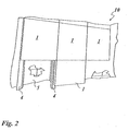
- a thermal insulation system 10 is shown, in which the insulation panels 1 are arranged on a building wall 5.
- the building wall 5 is the outer wall of a building, the outer plaster already has plaster damage.
- the consequently uneven building wall is leveled by an adhesive layer, not shown in Fig. 2, so that the insulation boards 1 form an insulating layer with a flat surface.
- dowels may be provided for fastening the insulation boards, which in particular improve the adhesive strength of the insulation boards under exceptional load, for example in vacuum formation on the board surface by storm.
- thermal insulation composite system 10 results from the fact that the insulation panels 1 in horizontal rows, beginning at the bottom row, are fixed on the building wall 5.
- the inserted between a series adjacent insulation boards vertical locking elements are used to secure the vertically aligned alignment with the next up and down following rows, with the inserted into the upper horizontal groove of said row horizontal locking elements the alignment of the insulating panels of a row and the Secure the front-facing alignment of the insulation boards in the next row up and down.
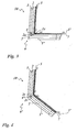
- Fig. 3 now shows the formation of a right-angled corner 6 in the thermal insulation system 10. It is an external corner.
- an adhesive layer 7 is applied, which fixes the insulation board 1 and an insulation board 1' on the building wall 5 and 5 '.
- the front side 1 s of the wall mounted on the building wall 5 insulation board 1 is aligned with the outside of the building wall 5 'applied adhesive layer 7, so that the building wall 5' facing back front side of the insulation board 1 in a plane with the end face of the insulation board 1 and Outside of the adhesive layer 7 extends, wherein the end face of the insulating board 1 is aligned with the front side front side of the insulating board 1.
- a groove 20 is introduced, which is arranged opposite the groove 2 formed in the end face of the insulating board 1 and is formed in cross section the same as the groove 2.
- the overlapping space formed by the two grooves 2, 20 forms a receiving space in which the vertically extending locking element 4 is inserted in a form-fitting manner.
- the introduced into the back plate surface groove 20 may be introduced either on site or during the insulation board production.
- the grooves 2r may be incorporated either at the construction site or during the insulation board production.
- it can be provided to produce the two insulating panels 1 and 1 'from an insulating board.
- a central through hole with the diameter of the locking element 2r is introduced, which is directed parallel to the two front sides of the upper end side to the lower end side, and that then a separating cut is introduced, wherein the cutting plane with the front sides includes half the corner angle and perpendicular to the upper or lower end side of the insulation board directed through the hole axis.
Landscapes
- Physics & Mathematics (AREA)
- Engineering & Computer Science (AREA)
- Architecture (AREA)
- Acoustics & Sound (AREA)
- Electromagnetism (AREA)
- Civil Engineering (AREA)
- Structural Engineering (AREA)
- Building Environments (AREA)
- Other Investigation Or Analysis Of Materials By Electrical Means (AREA)
- Separation Using Semi-Permeable Membranes (AREA)
- Load-Bearing And Curtain Walls (AREA)
Applications Claiming Priority (1)
| Application Number | Priority Date | Filing Date | Title |
|---|---|---|---|
| DE102006050046A DE102006050046A1 (de) | 2006-10-24 | 2006-10-24 | Wärmedämmverbundsystem |
Publications (3)
| Publication Number | Publication Date |
|---|---|
| EP1918469A2 true EP1918469A2 (fr) | 2008-05-07 |
| EP1918469A3 EP1918469A3 (fr) | 2008-09-10 |
| EP1918469B1 EP1918469B1 (fr) | 2010-12-01 |
Family
ID=38943300
Family Applications (1)
| Application Number | Title | Priority Date | Filing Date |
|---|---|---|---|
| EP07020665A Not-in-force EP1918469B1 (fr) | 2006-10-24 | 2007-10-23 | Système de raccordement d'isolation thermique |
Country Status (3)
| Country | Link |
|---|---|
| EP (1) | EP1918469B1 (fr) |
| AT (1) | ATE490374T1 (fr) |
| DE (2) | DE102006050046A1 (fr) |
Cited By (1)
| Publication number | Priority date | Publication date | Assignee | Title |
|---|---|---|---|---|
| CN102505777A (zh) * | 2011-10-16 | 2012-06-20 | 张宗楼 | 大型水平孔复合夹心保温墙板保温体系 |
Families Citing this family (1)
| Publication number | Priority date | Publication date | Assignee | Title |
|---|---|---|---|---|
| DE102017108138A1 (de) * | 2017-04-16 | 2018-10-18 | Wilhelm Brohlburg Kunststoff- und Kaschierwerke GmbH & Co. KG | Gefälle-Isolierplatte |
Citations (2)
| Publication number | Priority date | Publication date | Assignee | Title |
|---|---|---|---|---|
| DE8523833U1 (de) | 1985-08-20 | 1985-10-31 | Lehr, Helmut, 7152 Aspach | Vorrichtung zum Isolieren einer durch Außenwandflächen gebildeten Ecke |
| DE20114262U1 (de) | 2001-08-29 | 2001-10-31 | Schmidt, Peter, 39326 Meitzendorf | Profilierte Dämmplatte |
Family Cites Families (4)
| Publication number | Priority date | Publication date | Assignee | Title |
|---|---|---|---|---|
| GB1223256A (en) * | 1967-04-26 | 1971-02-24 | Electro Chem Eng | Improvements relating to electroplating |
| DE7811987U1 (de) * | 1978-04-20 | 1978-08-10 | Vki-Rheinhold & Mahla Ag, 6800 Mannheim | Bauplatte, insbesondere daemmplatte |
| DE20221262U1 (de) * | 2001-08-23 | 2005-09-15 | Rockwool Mineralwolle | In einem hinterlüfteten Wärmedämmverbundsystem verwendbare Dämmplatte |
| DE202006004169U1 (de) * | 2006-03-14 | 2006-08-17 | Vaku-Isotherm Gmbh | Wärmedämmsystem mit Vakuumisolationspaneelen in Sandwichbauweise |
-
2006
- 2006-10-24 DE DE102006050046A patent/DE102006050046A1/de not_active Withdrawn
-
2007
- 2007-10-23 EP EP07020665A patent/EP1918469B1/fr not_active Not-in-force
- 2007-10-23 AT AT07020665T patent/ATE490374T1/de active
- 2007-10-23 DE DE502007005825T patent/DE502007005825D1/de active Active
Patent Citations (2)
| Publication number | Priority date | Publication date | Assignee | Title |
|---|---|---|---|---|
| DE8523833U1 (de) | 1985-08-20 | 1985-10-31 | Lehr, Helmut, 7152 Aspach | Vorrichtung zum Isolieren einer durch Außenwandflächen gebildeten Ecke |
| DE20114262U1 (de) | 2001-08-29 | 2001-10-31 | Schmidt, Peter, 39326 Meitzendorf | Profilierte Dämmplatte |
Cited By (2)
| Publication number | Priority date | Publication date | Assignee | Title |
|---|---|---|---|---|
| CN102505777A (zh) * | 2011-10-16 | 2012-06-20 | 张宗楼 | 大型水平孔复合夹心保温墙板保温体系 |
| CN102505777B (zh) * | 2011-10-16 | 2016-01-06 | 张宗楼 | 大型水平孔复合夹心保温墙板保温体系 |
Also Published As
| Publication number | Publication date |
|---|---|
| DE102006050046A1 (de) | 2008-05-08 |
| ATE490374T1 (de) | 2010-12-15 |
| EP1918469B1 (fr) | 2010-12-01 |
| EP1918469A3 (fr) | 2008-09-10 |
| DE502007005825D1 (de) | 2011-01-13 |
Similar Documents
| Publication | Publication Date | Title |
|---|---|---|
| EP2639394B1 (fr) | Bande pour bordure de mur, entourage de fenêtre et structure de mur dotée de bandes pour bordure de mur | |
| EP0560013B1 (fr) | Panneau en bois | |
| WO2010145642A2 (fr) | Coffrage perdu | |
| DE202014000932U1 (de) | Trockenbauplatte und Trockenbauwand | |
| EP4257768B1 (fr) | Ensemble d'éléments de construction pour un bâtiment en bois | |
| DE10043609C1 (de) | Mauerwerk | |
| EP1918469B1 (fr) | Système de raccordement d'isolation thermique | |
| DE9207654U1 (de) | Holzbautafel | |
| DE9302447U1 (de) | Holzbautafel | |
| EP2080845A1 (fr) | Elément préfabriqué en bois | |
| DE19723341A1 (de) | Bauelement für Gebäudewände | |
| DE102005033834B4 (de) | Holzständerwand | |
| DE202010010158U1 (de) | Bausatz zur Herstellung eines Holzhauses in Vollholz-Blockbauweise sowie daraus hergestelltes Holzhaus | |
| EP1911882A2 (fr) | Système de fabrication d'un revêtement pour un toit, un sol ou analogue, sur lequel on peut marcher ou rouler. | |
| AT520334B1 (de) | Mauerstein | |
| DE102017114619B4 (de) | System aus zumindest zwei Transporthaken und einem vorgefertigten Wandelement und Verfahren zur Herstellung eines vorgefertigten Wandelements | |
| DE2263027A1 (de) | Aus kurzen holzteilen zusammengesetztes bauteil | |
| EP3577286A1 (fr) | Système de construction | |
| DE102004003366B4 (de) | Verfahren zum Herstellen eines Einfamilien-oder Mehrfamilienhauses, Betonfertigteil-Trogplatte für eine Gebäudedecke sowie Fertighaus | |
| EP1626134A1 (fr) | Maison en bois et procédé de construction associé | |
| EP1995387A2 (fr) | Composant en bois et élément mural formé à l'aide de celui-ci | |
| DE3200999A1 (de) | Mauerwerk | |
| EP3798377B1 (fr) | Procédé de fabrication d'une construction | |
| DE905883C (de) | Verfahren zur Herstellung insbesondere von Aussen- und Zwischenwaenden von Gebaeuden | |
| DE29724732U1 (de) | Holzbautafel |
Legal Events
| Date | Code | Title | Description |
|---|---|---|---|
| PUAI | Public reference made under article 153(3) epc to a published international application that has entered the european phase |
Free format text: ORIGINAL CODE: 0009012 |
|
| AK | Designated contracting states |
Kind code of ref document: A2 Designated state(s): AT BE BG CH CY CZ DE DK EE ES FI FR GB GR HU IE IS IT LI LT LU LV MC MT NL PL PT RO SE SI SK TR |
|
| AX | Request for extension of the european patent |
Extension state: AL BA HR MK RS |
|
| PUAL | Search report despatched |
Free format text: ORIGINAL CODE: 0009013 |
|
| AK | Designated contracting states |
Kind code of ref document: A3 Designated state(s): AT BE BG CH CY CZ DE DK EE ES FI FR GB GR HU IE IS IT LI LT LU LV MC MT NL PL PT RO SE SI SK TR |
|
| AX | Request for extension of the european patent |
Extension state: AL BA HR MK RS |
|
| 17P | Request for examination filed |
Effective date: 20081204 |
|
| AKX | Designation fees paid |
Designated state(s): AT BE BG CH CY CZ DE DK EE ES FI FR GB GR HU IE IS IT LI LT LU LV MC MT NL PL PT RO SE SI SK TR |
|
| 17Q | First examination report despatched |
Effective date: 20090504 |
|
| GRAP | Despatch of communication of intention to grant a patent |
Free format text: ORIGINAL CODE: EPIDOSNIGR1 |
|
| GRAS | Grant fee paid |
Free format text: ORIGINAL CODE: EPIDOSNIGR3 |
|
| GRAA | (expected) grant |
Free format text: ORIGINAL CODE: 0009210 |
|
| AK | Designated contracting states |
Kind code of ref document: B1 Designated state(s): AT BE BG CH CY CZ DE DK EE ES FI FR GB GR HU IE IS IT LI LT LU LV MC MT NL PL PT RO SE SI SK TR |
|
| REG | Reference to a national code |
Ref country code: GB Ref legal event code: FG4D Free format text: NOT ENGLISH |
|
| REG | Reference to a national code |
Ref country code: CH Ref legal event code: EP |
|
| REG | Reference to a national code |
Ref country code: IE Ref legal event code: FG4D |
|
| REF | Corresponds to: |
Ref document number: 502007005825 Country of ref document: DE Date of ref document: 20110113 Kind code of ref document: P |
|
| REG | Reference to a national code |
Ref country code: NL Ref legal event code: VDEP Effective date: 20101201 |
|
| PG25 | Lapsed in a contracting state [announced via postgrant information from national office to epo] |
Ref country code: LT Free format text: LAPSE BECAUSE OF FAILURE TO SUBMIT A TRANSLATION OF THE DESCRIPTION OR TO PAY THE FEE WITHIN THE PRESCRIBED TIME-LIMIT Effective date: 20101201 |
|
| LTIE | Lt: invalidation of european patent or patent extension |
Effective date: 20101201 |
|
| PG25 | Lapsed in a contracting state [announced via postgrant information from national office to epo] |
Ref country code: LV Free format text: LAPSE BECAUSE OF FAILURE TO SUBMIT A TRANSLATION OF THE DESCRIPTION OR TO PAY THE FEE WITHIN THE PRESCRIBED TIME-LIMIT Effective date: 20101201 Ref country code: CY Free format text: LAPSE BECAUSE OF FAILURE TO SUBMIT A TRANSLATION OF THE DESCRIPTION OR TO PAY THE FEE WITHIN THE PRESCRIBED TIME-LIMIT Effective date: 20101201 Ref country code: SE Free format text: LAPSE BECAUSE OF FAILURE TO SUBMIT A TRANSLATION OF THE DESCRIPTION OR TO PAY THE FEE WITHIN THE PRESCRIBED TIME-LIMIT Effective date: 20101201 Ref country code: FI Free format text: LAPSE BECAUSE OF FAILURE TO SUBMIT A TRANSLATION OF THE DESCRIPTION OR TO PAY THE FEE WITHIN THE PRESCRIBED TIME-LIMIT Effective date: 20101201 Ref country code: BG Free format text: LAPSE BECAUSE OF FAILURE TO SUBMIT A TRANSLATION OF THE DESCRIPTION OR TO PAY THE FEE WITHIN THE PRESCRIBED TIME-LIMIT Effective date: 20110301 Ref country code: NL Free format text: LAPSE BECAUSE OF FAILURE TO SUBMIT A TRANSLATION OF THE DESCRIPTION OR TO PAY THE FEE WITHIN THE PRESCRIBED TIME-LIMIT Effective date: 20101201 Ref country code: SI Free format text: LAPSE BECAUSE OF FAILURE TO SUBMIT A TRANSLATION OF THE DESCRIPTION OR TO PAY THE FEE WITHIN THE PRESCRIBED TIME-LIMIT Effective date: 20101201 |
|
| REG | Reference to a national code |
Ref country code: IE Ref legal event code: FD4D |
|
| PG25 | Lapsed in a contracting state [announced via postgrant information from national office to epo] |
Ref country code: GR Free format text: LAPSE BECAUSE OF FAILURE TO SUBMIT A TRANSLATION OF THE DESCRIPTION OR TO PAY THE FEE WITHIN THE PRESCRIBED TIME-LIMIT Effective date: 20110302 |
|
| PG25 | Lapsed in a contracting state [announced via postgrant information from national office to epo] |
Ref country code: CZ Free format text: LAPSE BECAUSE OF FAILURE TO SUBMIT A TRANSLATION OF THE DESCRIPTION OR TO PAY THE FEE WITHIN THE PRESCRIBED TIME-LIMIT Effective date: 20101201 Ref country code: IE Free format text: LAPSE BECAUSE OF FAILURE TO SUBMIT A TRANSLATION OF THE DESCRIPTION OR TO PAY THE FEE WITHIN THE PRESCRIBED TIME-LIMIT Effective date: 20101201 Ref country code: ES Free format text: LAPSE BECAUSE OF FAILURE TO SUBMIT A TRANSLATION OF THE DESCRIPTION OR TO PAY THE FEE WITHIN THE PRESCRIBED TIME-LIMIT Effective date: 20110312 Ref country code: IS Free format text: LAPSE BECAUSE OF FAILURE TO SUBMIT A TRANSLATION OF THE DESCRIPTION OR TO PAY THE FEE WITHIN THE PRESCRIBED TIME-LIMIT Effective date: 20110401 Ref country code: EE Free format text: LAPSE BECAUSE OF FAILURE TO SUBMIT A TRANSLATION OF THE DESCRIPTION OR TO PAY THE FEE WITHIN THE PRESCRIBED TIME-LIMIT Effective date: 20101201 Ref country code: PT Free format text: LAPSE BECAUSE OF FAILURE TO SUBMIT A TRANSLATION OF THE DESCRIPTION OR TO PAY THE FEE WITHIN THE PRESCRIBED TIME-LIMIT Effective date: 20110401 |
|
| PG25 | Lapsed in a contracting state [announced via postgrant information from national office to epo] |
Ref country code: PL Free format text: LAPSE BECAUSE OF FAILURE TO SUBMIT A TRANSLATION OF THE DESCRIPTION OR TO PAY THE FEE WITHIN THE PRESCRIBED TIME-LIMIT Effective date: 20101201 Ref country code: SK Free format text: LAPSE BECAUSE OF FAILURE TO SUBMIT A TRANSLATION OF THE DESCRIPTION OR TO PAY THE FEE WITHIN THE PRESCRIBED TIME-LIMIT Effective date: 20101201 Ref country code: RO Free format text: LAPSE BECAUSE OF FAILURE TO SUBMIT A TRANSLATION OF THE DESCRIPTION OR TO PAY THE FEE WITHIN THE PRESCRIBED TIME-LIMIT Effective date: 20101201 |
|
| PLBE | No opposition filed within time limit |
Free format text: ORIGINAL CODE: 0009261 |
|
| STAA | Information on the status of an ep patent application or granted ep patent |
Free format text: STATUS: NO OPPOSITION FILED WITHIN TIME LIMIT |
|
| PG25 | Lapsed in a contracting state [announced via postgrant information from national office to epo] |
Ref country code: DK Free format text: LAPSE BECAUSE OF FAILURE TO SUBMIT A TRANSLATION OF THE DESCRIPTION OR TO PAY THE FEE WITHIN THE PRESCRIBED TIME-LIMIT Effective date: 20101201 |
|
| 26N | No opposition filed |
Effective date: 20110902 |
|
| REG | Reference to a national code |
Ref country code: DE Ref legal event code: R097 Ref document number: 502007005825 Country of ref document: DE Effective date: 20110902 |
|
| PG25 | Lapsed in a contracting state [announced via postgrant information from national office to epo] |
Ref country code: IT Free format text: LAPSE BECAUSE OF FAILURE TO SUBMIT A TRANSLATION OF THE DESCRIPTION OR TO PAY THE FEE WITHIN THE PRESCRIBED TIME-LIMIT Effective date: 20101201 |
|
| BERE | Be: lapsed |
Owner name: SAINT-GOBAIN WEBER "TERRANOVA" GMBH Effective date: 20111031 |
|
| PG25 | Lapsed in a contracting state [announced via postgrant information from national office to epo] |
Ref country code: MC Free format text: LAPSE BECAUSE OF NON-PAYMENT OF DUE FEES Effective date: 20111031 |
|
| REG | Reference to a national code |
Ref country code: CH Ref legal event code: PL |
|
| GBPC | Gb: european patent ceased through non-payment of renewal fee |
Effective date: 20111023 |
|
| REG | Reference to a national code |
Ref country code: CH Ref legal event code: NV Representative=s name: FIAMMENGHI-FIAMMENGHI Ref country code: CH Ref legal event code: AEN Free format text: DAS PATENT IST AUFGRUND DES WEITERBEHANDLUNGSANTRAGS VOM 05.07.2012 REAKTIVIERT WORDEN. |
|
| REG | Reference to a national code |
Ref country code: FR Ref legal event code: ST Effective date: 20120629 |
|
| PG25 | Lapsed in a contracting state [announced via postgrant information from national office to epo] |
Ref country code: CH Free format text: LAPSE BECAUSE OF NON-PAYMENT OF DUE FEES Effective date: 20111031 Ref country code: BE Free format text: LAPSE BECAUSE OF NON-PAYMENT OF DUE FEES Effective date: 20111031 Ref country code: LI Free format text: LAPSE BECAUSE OF NON-PAYMENT OF DUE FEES Effective date: 20111031 |
|
| PG25 | Lapsed in a contracting state [announced via postgrant information from national office to epo] |
Ref country code: FR Free format text: LAPSE BECAUSE OF NON-PAYMENT OF DUE FEES Effective date: 20111102 Ref country code: GB Free format text: LAPSE BECAUSE OF NON-PAYMENT OF DUE FEES Effective date: 20111023 |
|
| PGRI | Patent reinstated in contracting state [announced from national office to epo] |
Ref country code: CH Effective date: 20120705 Ref country code: LI Effective date: 20120705 |
|
| PG25 | Lapsed in a contracting state [announced via postgrant information from national office to epo] |
Ref country code: MT Free format text: LAPSE BECAUSE OF FAILURE TO SUBMIT A TRANSLATION OF THE DESCRIPTION OR TO PAY THE FEE WITHIN THE PRESCRIBED TIME-LIMIT Effective date: 20101201 |
|
| PG25 | Lapsed in a contracting state [announced via postgrant information from national office to epo] |
Ref country code: LU Free format text: LAPSE BECAUSE OF NON-PAYMENT OF DUE FEES Effective date: 20111023 |
|
| PG25 | Lapsed in a contracting state [announced via postgrant information from national office to epo] |
Ref country code: TR Free format text: LAPSE BECAUSE OF FAILURE TO SUBMIT A TRANSLATION OF THE DESCRIPTION OR TO PAY THE FEE WITHIN THE PRESCRIBED TIME-LIMIT Effective date: 20101201 |
|
| PG25 | Lapsed in a contracting state [announced via postgrant information from national office to epo] |
Ref country code: HU Free format text: LAPSE BECAUSE OF FAILURE TO SUBMIT A TRANSLATION OF THE DESCRIPTION OR TO PAY THE FEE WITHIN THE PRESCRIBED TIME-LIMIT Effective date: 20101201 |
|
| PGFP | Annual fee paid to national office [announced via postgrant information from national office to epo] |
Ref country code: DE Payment date: 20140927 Year of fee payment: 8 Ref country code: CH Payment date: 20141024 Year of fee payment: 8 |
|
| PGFP | Annual fee paid to national office [announced via postgrant information from national office to epo] |
Ref country code: AT Payment date: 20141022 Year of fee payment: 8 |
|
| REG | Reference to a national code |
Ref country code: DE Ref legal event code: R119 Ref document number: 502007005825 Country of ref document: DE |
|
| REG | Reference to a national code |
Ref country code: CH Ref legal event code: PL |
|
| REG | Reference to a national code |
Ref country code: AT Ref legal event code: MM01 Ref document number: 490374 Country of ref document: AT Kind code of ref document: T Effective date: 20151023 |
|
| PG25 | Lapsed in a contracting state [announced via postgrant information from national office to epo] |
Ref country code: CH Free format text: LAPSE BECAUSE OF NON-PAYMENT OF DUE FEES Effective date: 20151031 Ref country code: LI Free format text: LAPSE BECAUSE OF NON-PAYMENT OF DUE FEES Effective date: 20151031 Ref country code: DE Free format text: LAPSE BECAUSE OF NON-PAYMENT OF DUE FEES Effective date: 20160503 |
|
| PG25 | Lapsed in a contracting state [announced via postgrant information from national office to epo] |
Ref country code: AT Free format text: LAPSE BECAUSE OF NON-PAYMENT OF DUE FEES Effective date: 20151023 |