EP0103370A1 - Gasturbinenmotoren - Google Patents
Gasturbinenmotoren Download PDFInfo
- Publication number
- EP0103370A1 EP0103370A1 EP83304089A EP83304089A EP0103370A1 EP 0103370 A1 EP0103370 A1 EP 0103370A1 EP 83304089 A EP83304089 A EP 83304089A EP 83304089 A EP83304089 A EP 83304089A EP 0103370 A1 EP0103370 A1 EP 0103370A1
- Authority
- EP
- European Patent Office
- Prior art keywords
- turbine
- power plant
- engine
- compressor
- shaft
- Prior art date
- Legal status (The legal status is an assumption and is not a legal conclusion. Google has not performed a legal analysis and makes no representation as to the accuracy of the status listed.)
- Withdrawn
Links
- 238000002485 combustion reaction Methods 0.000 claims abstract description 17
- 239000007789 gas Substances 0.000 claims description 37
- 230000008878 coupling Effects 0.000 claims description 9
- 238000010168 coupling process Methods 0.000 claims description 9
- 238000005859 coupling reaction Methods 0.000 claims description 9
- 239000000446 fuel Substances 0.000 claims description 8
- 239000011159 matrix material Substances 0.000 claims description 3
- 238000000034 method Methods 0.000 claims 2
- 230000000694 effects Effects 0.000 abstract description 10
- 239000003570 air Substances 0.000 description 19
- 230000005540 biological transmission Effects 0.000 description 4
- 238000001816 cooling Methods 0.000 description 3
- 238000010521 absorption reaction Methods 0.000 description 2
- 230000007423 decrease Effects 0.000 description 2
- 239000012080 ambient air Substances 0.000 description 1
- 230000000740 bleeding effect Effects 0.000 description 1
- 238000007664 blowing Methods 0.000 description 1
- 239000002826 coolant Substances 0.000 description 1
- 230000003247 decreasing effect Effects 0.000 description 1
- 230000003467 diminishing effect Effects 0.000 description 1
- 239000000463 material Substances 0.000 description 1
- 239000000203 mixture Substances 0.000 description 1
Images


Classifications
-
- F—MECHANICAL ENGINEERING; LIGHTING; HEATING; WEAPONS; BLASTING
- F02—COMBUSTION ENGINES; HOT-GAS OR COMBUSTION-PRODUCT ENGINE PLANTS
- F02C—GAS-TURBINE PLANTS; AIR INTAKES FOR JET-PROPULSION PLANTS; CONTROLLING FUEL SUPPLY IN AIR-BREATHING JET-PROPULSION PLANTS
- F02C7/00—Features, components parts, details or accessories, not provided for in, or of interest apart form groups F02C1/00 - F02C6/00; Air intakes for jet-propulsion plants
- F02C7/08—Heating air supply before combustion, e.g. by exhaust gases
-
- F—MECHANICAL ENGINEERING; LIGHTING; HEATING; WEAPONS; BLASTING
- F02—COMBUSTION ENGINES; HOT-GAS OR COMBUSTION-PRODUCT ENGINE PLANTS
- F02C—GAS-TURBINE PLANTS; AIR INTAKES FOR JET-PROPULSION PLANTS; CONTROLLING FUEL SUPPLY IN AIR-BREATHING JET-PROPULSION PLANTS
- F02C7/00—Features, components parts, details or accessories, not provided for in, or of interest apart form groups F02C1/00 - F02C6/00; Air intakes for jet-propulsion plants
- F02C7/36—Power transmission arrangements between the different shafts of the gas turbine plant, or between the gas-turbine plant and the power user
Definitions
- This invention relates to gas turbine engines, and is particularly concerned with gas turbines for land vehicle propulsion.
- Such engines usually employ a heat exchanger to recover some of the heat energy from the engine exhaust gases to enable the engine to operate with acceptable efficiency at part load.
- a conventional layout of gas turbine engine usually comprises an axial array of components comprising in flow series, a compressor or compressors, a combustion system in which fuel is burnt with air from the compressors, a high pressure turbine or turbines driven by the gases from the combustion system and which in turn drive the respective compressors, and a low pressure power turbine to drive a load such as a vehicle through a suitable transmission system.
- a heat exchanger can be incorporated in such a conventional layout but the ducting to take the exhaust gases through one path of the heat exchanger and for the compressor delivery air to flow through the other path of the heat exchaanger would be complex and lengthy. The resulting conventional layout and heat exchanger would be relatively heavy and occupy a large volume.
- TET high pressure turbine entry temperature
- adjustable nozzle guide vanes for the low pressure power turbine. These vanes enable the division of work between the compressor driving turbine and the power turbine to be adjusted so that the engine mass flow is controlled to give a reasonably high TET through the most useful part of the power range.
- variable incidence power turbine nozzle guide vanes are undesirable for a number of reasons, e.g., inefficiencies arise from the leakage flow between the vane ends and the engine casings, and because the rotor geometry is fixed, the rotor blade incidences at the extremes of the nozzle guide vane movement are less than optimum. Also, reliable operation of variable vanes at high temperatures present significant design problems.
- High temperature operation requires minimisation of the surface area of those components in contact with the hot gas stream, particularly since the component cooling medium may comprise the compressor delivery air which has already passed through the heat exchanger.
- An engine layout which has a combustor of minimum area directly coupled to the high pressure turbine would materially assist in surface area minimisation.
- Access to components, particuarly the high temperature components, in a conventionalheat exchanged gas turbine can be a problem and an engine layout in which the high temperature components, e.g. the combustor and the high pressure turbine are readily to hand, is desirable it is also desirable that the engine can be started by towing the vehicle in which the engine is located, and that the engine can provide a braking effect when the vehicle over-runs the engine. It is also necessary to provide some means of preventing over- speed of the high pressure turbine, e.g. in the event of a loss of load.
- Both designs utilise a reverse flow layout, i.e., the high pressure turbine is the power turbine, and the low pressure turbine drives the engine compressor.
- the designs also have the capability of coupling the high and low pressure shafts together, under certain conditions.
- the present invention seeks to provide a reverse flow heat exchanged automotive gas turbine engine which overcomes the problems outlined above and which avoids the problems associated with a conventional heat exchanged gas turbine.
- the present invention seeks to provide a gas turbine engine for a land vehicle which can operate at high TET's over a useful power range, avoids excessively high TET's without the need for variable incidence power turbine nozzle guide vanes, and which orevents compressor surge and is compact.
- the present layout is unconventional in that the high pressure turbine comprises the power turbine which drives the vehicle through a suitable transmission system, and the low pressure turbine drives the engine compressor.
- the power turbine does not have any variable incidence nozzle guide vanes.
- This reverse flow cycle enables a high TET to be maintained over the most useful part of the power range, even at part load conditions.
- the aerodynamic and mechanical design of the engine enables the engine to operate either in a two shaft or single shaft mode, the two shaft mode enabling the high TET to be maintained and the single shaft mode preventing excessive TET's and compressor surge.
- the reverse flow layout allows the combustor to be positioned at the downstream end of the engine and for the heat exchanger to be located in a position which minimises the length and complexity of the heat exchanger feed and exhaust ducting.
- the surface area of the combustor and turbine entry duct can be minimised and both the combustor and the turbines are easily accessible since they are at one end of the engine and not buried within the engine by various casings and heat exchanger ducting.
- the shafts can be coupled together by a sprag clutch, or any other suitable coupling device to enable the engine to operate in the two modes.
- the engine compressor can comprise a centrifugal type of compressor because of its capability of handling a wide flow range.
- Engine starting with a reverse flow layout can be a significant problem because the energy in the gas stream appears predominantly in the high pressure (power) turbine and there will be insufficient energy in the low pressure turbine to drive the engine compressor to render the engine self-sustaining.
- the sprag clutch enables the engine to operate in the single shaft mode during the starting operation because at low speeds the shafts will rotate together, and the high pressure turbine will assist the low pressure turbine. As soon as the engine is self-sustaining, the speed difference between the shafts can increase and the sprag clutch will disengage.
- Another advantage of the ability to couple the shafts together is that a vehicle can be tow started because the engine can be driven through the vehicle transmission and the coupled engine shafts.
- a further advantage is that over-speed of the power turbine (e.g. through loss of load) is checked by engagement of the sprag clutch.
- the engine then operates as a single shaft engine, and the high pressure turbine energy is absorbed in driving the engine compressor.
- the sprag clutch can be arranged to ewgage/dis- engage when the shaft speeds are equal or when there is some pre-determined speed ratio between the two shafts. This latter condition can be accomplished by the use of a layshaft and an appropriate ratio gear box.
- the present invention provides a gas turbine engine power plant comprising in flow series compressor means, heat exchange means having at least two flow paths in heat exchange relationship, compressor delivery air flowing through one of said flow paths, combustion means arranged to receive the compressor delivery air from the heat exchange means and a supply of fuel, high pressure turbine means arranged to receive the products of combustion and to drive a load through a first shaft, low pressure turbine means arranged to drive the compressor means through a second shaft, the exhaust gases from the low pressure turbine exhausting to atmosphere through the heat exchanger in heat exchange relationship with the compressor delivery air, the shafts having coupling means enabling the engine to operate in either a two shaft or a single shaft mode, the two shaft mode enabling the engine to operate at a high turbine entry temperature through a useful power range, and to operate in the single shaft mode to prevent excessive turbine entry temperatures and compressor surge.
- the shaft engagement/disengagement may be arranged to occur when the shaft speeds are substantially the same, or at some pre-determined speed ratio between them.
- the combustion means and the high pressure turbine means can be located at the downstream end of the engine, and the combustion means may be of the fully annular type and located at the most downstream end of the engine.
- the high pressure turbine means may comprise an axial or a centripetal turbine.
- the low pressure turbine may comprise an axial flow turbine having one or more stages.
- the first and second shafts can be co-axial and the output drive from the first shaft can be located at the front end of the engine.
- the engine can have a layshaft and a fixed ratio gear box connecting the first and second shafts together through the coupling means.
- the coupling means between the two shafts may comprise a sprag clutch, but any free-wheel mechanism or clutch providing engagement or disengagement at the required speeds may be used.
- the heat exchange means can comprise a stationary annular matrix having separate flow paths in heat exchange relationship for the compressor delivery air and the low pressure turbine exhaust gases.
- the annular heat.exchanger can be located axially so that it at least partially surrounds the high and/or the low pressure turbines.
- a gas turbine engine power plant 10 comprises a two-stage centrifugal compressor 12 driven by-a two stage axial turbine 14 through a shaft 16.
- the exhaust gases from the turbine drive a two-stage power turbine 18 which has variable inlet guide vanes 20, and the power turbine drives a load (not shown) via a shaft 22 and a gear box 24.
- the power turbine exhaust gases flow through a heat exchanger 26 in heat exchange relationship with delivery air from the compressor 12, which after being heated flows into a combustor 28 where it is mixed with fuel and burnt.
- the products of combustion then drive the turbine 14.
- variable inlet guide vanes for the power turbine are required to control the division of work between the turbine 18 and the compressor driving turbine 14.
- the engine in a land vehicle application would not provide engine braking in an engine over-run situation.
- a separate shaft (not shown) is required.
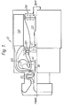
- a gas turbine power plant 110 comprises a two stage centrifugal compressor 112 driven by a two stage low pressure axial turbine 114 via shaft 116.
- the compressor delivery air flows into a heat exchanger 126 which has a flow path for the compressed air in heat exchange relationship with hot turbine exhaust gases in another flow path, the flow paths not being shown.
- the heated compressor delivery air flows into an annular combustion-chamber 128 which also receives a supply of fuel, and where the fuel and air mixture is burnt.
- the products of combustion then flow through fixed nozzle guide vanes 120 to drive a high pressure turbine 118 which is arranged to drive a load (not shown) via a shaft 122 which is co-axial with the shaft 116, and located internally of the shaft 116.
- a free wheel mechanism 130 such as a sprag clutch, enables the shafts 116 and 122 to be coupled together and disengaged as will be described below.
- the annular combustion chamber 128 is located at the rear end of the engine and is enclosed by a readily removable cover plate 132 which enables both the combustion chamber and the turbines 114 and 118 to be easily accessible.
- the heat exchanger 126 is an annular matrix which partially surrounds the turbines 114, 118 thereby reducing the overall length of the power plant.
- the feed and supply ducting for the heat exchanger comprises a volute 134 at the outlet from the downstream stage of the compressor 112 feeding an inlet duct 136 t6 the heat exchanger, the inlet duct being approximately in the shape of an annular segment in section.
- the feed for the heated compressor delivery air from the heat exchanger to the combustion chamber comprises an annular air casing 138, and the supply of hot exhaust gases to the heat exchanger also comprises an annular air casing 140.
- the ducting for the heat exchanger is extremely simple and short in length, which enables weight and volume to be kept to a minimum.
- gas turbine engines operate at peak efficiency at one design point only, the design .point being defined by power, engine speed, altitude in the case of aero-engines and ambient conditions. At off design point conditions gas turbines are relatively inefficient as compared with diesel engines, for example. In order to improve the off design point efficiency, heat exchangers have to be used, and for maximum efficiency the engine should be run at a high temperature over the most used part of the engine power range. As shown in fig.
- the high turbine temperature (TET) is obtained by the use of variable inlet guide vanes to the power turbine.
- TET variable inlet guide vanes
- This enables the division,of work to be controlled as between the power turbine and the compressor driving turbine, thereby providing control of the compressor speed and mass flow.
- the use of variable inlet guide vanes is undesirable for a number of reasons.
- Land vehicles rarely operate at a constant power for long periods and powers tend to vary considerably within a power range of say 20%-100% of full power.
- the engine operates as a normal two shaft gas turbine when running within this power range.
- the engine of fig. 2 has to operate within the area defined by the surge line and the choke line with a margin between the surge line and the actual line along which the engine operates.
- the engine performance is also optimised for the most used power range, i.e. over this range, TET is kept high, and component efficiencies are optimum.
- the surge margin reduces and in order to maintain a working surge margin the engine is operated in a single shaft mode at these lower powers.
- This mode as achieved by the use of the free wheel mechanism 130 which engages naturally to couple the shafts 116, 122 together because the low pressure shaft speed falls more rapidly than the high pressure shaft speed during deceleration.
- the speed at which engagement and disengagement occurs can be chosen by suitable aero-dynamic design of the turbines.
- the use of the free-wheel mechanism allows the engine to provide a braking effect on the vehicle when the vehicle over-runs the engine on downhill gradients. This is because in this condition the engine will be in the single shaft mode and the power absorption capability of the compressor is close to the nett full power out put of the engine. In this situation, the compressor would preferably need an exit bleed valve to reduce the cooling effect on the heat exchanger.
- the free-wheel mechanism allows the vehicle to be tow started and aids considerably engine starting in general, since unless the shafts are coupled, it is impossible for the engine to be self sustaining at low powers.
- the arrangement of fig. 2 provides an extremely compact heat exchanged engine which is self controlling as far as TET over most of the power range is concerend, is easily accessible, and provides a braking effect without the need for external shafting.
- the engine configuration also checks power turbine overspeed in the event of loss of load.
- the engine is primarily intended for land vehicle propulsion, it can be adapted for aero-propulsion, e.g. helicopters.
- centripetal turbine 118a A characteristic of centripetal turbines is that capacity changes with speed. At high speeds, the capacity is lower than that at low speeds, as compared with an axial turbine in which capacity is fairly constant with speed. As has already been discussed the work share of the high pressure turbine increases as the engine pressure ratio decreases, and depending upon the capacity required of the high pressure turbine at part load conditions, a centripetal turbine may offer a more flexible design choice than an axial turbine.
- this engine operates in the same way-as the engine of fig. 2 and has the same advantages.
- the arrangement shown in fig. 4 is similar to the arrangements shown in figs. 2 and 3, and once again the same components have been given the same reference numbers.
- the high pressure turbine 118b is of the axial type and comprises two stages and the low pressure turbine 114a is also of the axial type and comprises one stage only.
- the engine compressor 112a is of the axial type and comprises two stages, and includes variable incidence inlet guide vanes 138.
- the power turbine shaft 122 drives a gar 150 which in turn drives a gear 152 mounted on the layshaft 144.
- a gear 154 on the layshaft drives a gear 156 on a shaft 158.
- the shaft 158 extends into an extension of the compressor shaft 116 which contains the sprag clutch 130. In effect, the shaft 158 is an extension of the shaft 122.
- the shaft 158 will run at the same speed as the shaft 122 and the sprag clutch is designed to engage/disengage when the compressor shaft 116 speed is the same as the power turbine speed.
- the gear boxes 140,142 are designed so the gear ratios can be changed by the use of different diameter gears enabling the shaft 158 to run at a different speed to the shaft ⁇ 122.
- the sprag clutch can be designed so that it will engage/disengage at some pre-determined speed ratio between the shafts 158 and 116. This will allow the engine to be more flexible, and in effect allows the engage/disengage line on fig. 6 as will be explained below, to be more to the left or right.
- either one or both of the gear boxes 140, 142 can be a variable change speed gear box.
- these vanes are referenced 114a and are shown as being of variable incidence.
- variable incidence vanes are to be avoided if possible, the degree of variation required for the low pressure turbine is considerably less than would be required if the vanes had to be varied on the high pressure turbine.
- aerodynamic means For example by blowing air from vanes into the nozzle passages between adjacent vanes or by bleeding air from these passages.
- the low pressure turbine will do more work and the low pressure compressor mass flow will be higher.
- the air fuel ratio will then be such that the combustion and turbine entry temperatures will be lower than they would have been if the low pressure turbine work had not been increased.
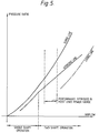
- Fig. 6 illustrates graphically the effect of the engine operating in a two shaft or a single shaft mode and applies to the layouts shown in figs. 2, 3 and 4.
- the figure comprises a plot of power turbine speed v. power output, both parameters expressed as percentages of the maximum possible.
- Imposed on the graph are lines of constant turbine entry temperature which apply in-the two shaft and single shaft modes. In the bottom right hand corner in the shaded zone, there is an indication of the predicted turbine entry temperatures if the engine was notable to operate in a single shaft mode, and the likelihood of compressor surge.
- the engine In the normal course of operation when the vehicle is accelerating or travelling at a reasonably constant speed, the engine will be running in the two shaft mode e.g. the low pressure shaft will be running faster than the high pressure shaft and the sprag clutch will be disengaged. So the engine will be operating between the two plots A and B at temperatures within the range of approximately 1350 0 K to 1550°K.
- the shaded area under plot C indicates the turbine entry temperatures if the engine were allowed to continue operating in the two shaft mode. These temperatures would rise to over 2000 0 K which could not be tolerated by present day turbine materials even with blade cooling. Also, and just as importantly, the engine compressor would surge, causing still further rises in temperature, and thermal inefficiency.
- the plot B is the locus of points at which the power turbine speed equals the compressor speed, thus it represents the locus of points at which the sprag clutch engages/disengages.
- the sprag clutch can be arranged to engage or disengage when the speed ratio between the two shafts is at a certain value, this being attained by use of the layshaft (see fig. 4).
- the plot B is the locus of points at which the speed ratio between the two shafts is at a pre-determined value.
Landscapes
- Engineering & Computer Science (AREA)
- Chemical & Material Sciences (AREA)
- Combustion & Propulsion (AREA)
- Mechanical Engineering (AREA)
- General Engineering & Computer Science (AREA)
- Engine Equipment That Uses Special Cycles (AREA)
- Braking Arrangements (AREA)
- Supercharger (AREA)
Applications Claiming Priority (2)
| Application Number | Priority Date | Filing Date | Title |
|---|---|---|---|
| GB8223142 | 1982-08-11 | ||
| GB8223142 | 1982-08-11 |
Publications (1)
| Publication Number | Publication Date |
|---|---|
| EP0103370A1 true EP0103370A1 (de) | 1984-03-21 |
Family
ID=10532247
Family Applications (1)
| Application Number | Title | Priority Date | Filing Date |
|---|---|---|---|
| EP83304089A Withdrawn EP0103370A1 (de) | 1982-08-11 | 1983-07-14 | Gasturbinenmotoren |
Country Status (4)
| Country | Link |
|---|---|
| EP (1) | EP0103370A1 (de) |
| JP (1) | JPS5946326A (de) |
| IL (1) | IL69290A0 (de) |
| NO (1) | NO832751L (de) |
Cited By (24)
| Publication number | Priority date | Publication date | Assignee | Title |
|---|---|---|---|---|
| GB2198188A (en) * | 1986-11-20 | 1988-06-08 | Mtu Muenchen Gmbh | Gas turbine propulsion unit |
| WO2000020738A3 (en) * | 1998-09-25 | 2000-07-13 | Alm Dev Inc | Gas turbine engine |
| WO2000053908A1 (en) * | 1999-03-11 | 2000-09-14 | Alm Development, Inc. | Gas turbine engine |
| RU2179646C2 (ru) * | 2000-04-18 | 2002-02-20 | Открытое акционерное общество "Авиадвигатель" | Газотурбинная установка |
| US6363708B1 (en) | 1999-10-12 | 2002-04-02 | Alm Development, Inc. | Gas turbine engine |
| US6397576B1 (en) | 1999-10-12 | 2002-06-04 | Alm Development, Inc. | Gas turbine engine with exhaust compressor having outlet tap control |
| US6442945B1 (en) | 2000-08-04 | 2002-09-03 | Alm Development, Inc. | Gas turbine engine |
| US6460324B1 (en) | 1999-10-12 | 2002-10-08 | Alm Development, Inc. | Gas turbine engine |
| WO2013085641A1 (en) * | 2011-12-09 | 2013-06-13 | United Technologies Corporation | Gas turbine engine with variable overall pressure ratio |
| US8689561B2 (en) | 2009-09-13 | 2014-04-08 | Donald W. Kendrick | Vortex premixer for combustion apparatus |
| EP2341228A3 (de) * | 2010-01-04 | 2017-06-07 | General Electric Company | Turbomaschine mit miteinander gekuppelten Turbinenrädern |
| CN109236494A (zh) * | 2018-11-01 | 2019-01-18 | 夏丰 | 超高速推力矢量喷气发动机 |
| US10215052B2 (en) | 2017-03-14 | 2019-02-26 | Pratt & Whitney Canada Corp. | Inter-shaft bearing arrangement |
| US10316689B2 (en) | 2016-08-22 | 2019-06-11 | Rolls-Royce Corporation | Gas turbine engine health monitoring system with shaft-twist sensors |
| US10393027B2 (en) | 2016-07-19 | 2019-08-27 | Pratt & Whitney Canada Corp. | Gas turbine engine shaft architecture and associated method of disassembly |
| US10465611B2 (en) | 2016-09-15 | 2019-11-05 | Pratt & Whitney Canada Corp. | Reverse flow multi-spool gas turbine engine with aft-end accessory gearbox drivingly connected to both high pressure spool and low pressure spool |
| US10738709B2 (en) | 2017-02-09 | 2020-08-11 | Pratt & Whitney Canada Corp. | Multi-spool gas turbine engine |
| US10746188B2 (en) | 2017-03-14 | 2020-08-18 | Pratt & Whitney Canada Corp. | Inter-shaft bearing connected to a compressor boost system |
| US10808624B2 (en) | 2017-02-09 | 2020-10-20 | Pratt & Whitney Canada Corp. | Turbine rotor with low over-speed requirements |
| US10815899B2 (en) | 2016-11-15 | 2020-10-27 | Pratt & Whitney Canada Corp. | Gas turbine engine accessories arrangement |
| US11035293B2 (en) | 2016-09-15 | 2021-06-15 | Pratt & Whitney Canada Corp. | Reverse flow gas turbine engine with offset RGB |
| US11408352B2 (en) | 2016-09-15 | 2022-08-09 | Pratt & Whitney Canada Corp. | Reverse-flow gas turbine engine |
| US11536153B2 (en) | 2018-08-08 | 2022-12-27 | Pratt & Whitney Canada Corp. | Turboshaft gas turbine engine |
| CN115957707A (zh) * | 2022-12-08 | 2023-04-14 | 西安陕鼓动力股份有限公司 | 包含多反应器的马来酸酐制备系统及其运行方法 |
Families Citing this family (1)
| Publication number | Priority date | Publication date | Assignee | Title |
|---|---|---|---|---|
| JPH04358726A (ja) * | 1991-09-10 | 1992-12-11 | Mitsubishi Heavy Ind Ltd | 車両用ガスタービン |
Citations (8)
| Publication number | Priority date | Publication date | Assignee | Title |
|---|---|---|---|---|
| DE811891C (de) * | 1949-02-15 | 1951-08-23 | Parsons C A & Co Ltd | Anordnung zur Drehzahlregelung von Brennkraftturbinen-Anlagen |
| GB713839A (en) * | 1951-07-25 | 1954-08-18 | Albert Enticknap | Improvements in or relating to internal combustion turbines |
| GB724177A (en) * | 1951-12-11 | 1955-02-16 | Parsons & Co Ltd C A | Mechanical power producing combustion turbine plants |
| GB775786A (en) * | 1953-11-23 | 1957-05-29 | Svenska Turbinfab Ab | Improvements in and relating to gas turbine power plant |
| FR1183239A (fr) * | 1956-09-28 | 1959-07-03 | Daimler Benz Ag | Installation de turbine à gaz, en particulier pour l'entraînement de voitures automobiles |
| US3365892A (en) * | 1965-08-10 | 1968-01-30 | Derderian George | Turbomachine |
| GB1170793A (en) * | 1969-05-05 | 1969-11-19 | Fiat Spa | Power Turbine-Engine Unit |
| US4118927A (en) * | 1975-12-05 | 1978-10-10 | United Turbine Ab & Co. Kommanditbolag | Gas turbine power plant |
-
1983
- 1983-07-14 EP EP83304089A patent/EP0103370A1/de not_active Withdrawn
- 1983-07-21 IL IL69290A patent/IL69290A0/xx unknown
- 1983-07-28 NO NO832751A patent/NO832751L/no unknown
- 1983-08-10 JP JP58146290A patent/JPS5946326A/ja active Pending
Patent Citations (8)
| Publication number | Priority date | Publication date | Assignee | Title |
|---|---|---|---|---|
| DE811891C (de) * | 1949-02-15 | 1951-08-23 | Parsons C A & Co Ltd | Anordnung zur Drehzahlregelung von Brennkraftturbinen-Anlagen |
| GB713839A (en) * | 1951-07-25 | 1954-08-18 | Albert Enticknap | Improvements in or relating to internal combustion turbines |
| GB724177A (en) * | 1951-12-11 | 1955-02-16 | Parsons & Co Ltd C A | Mechanical power producing combustion turbine plants |
| GB775786A (en) * | 1953-11-23 | 1957-05-29 | Svenska Turbinfab Ab | Improvements in and relating to gas turbine power plant |
| FR1183239A (fr) * | 1956-09-28 | 1959-07-03 | Daimler Benz Ag | Installation de turbine à gaz, en particulier pour l'entraînement de voitures automobiles |
| US3365892A (en) * | 1965-08-10 | 1968-01-30 | Derderian George | Turbomachine |
| GB1170793A (en) * | 1969-05-05 | 1969-11-19 | Fiat Spa | Power Turbine-Engine Unit |
| US4118927A (en) * | 1975-12-05 | 1978-10-10 | United Turbine Ab & Co. Kommanditbolag | Gas turbine power plant |
Non-Patent Citations (2)
| Title |
|---|
| DIESEL ENGINEERING, vol. 74, no. 797, 1978 "KG5 from Kongsberg", page 122 * |
| J. KRUSCHIK "Die Gasturbine", 2nd edition, 1960, SPRINGER-VERLAG, Wien, pages 416-421, 427-428 * |
Cited By (39)
| Publication number | Priority date | Publication date | Assignee | Title |
|---|---|---|---|---|
| GB2198188B (en) * | 1986-11-20 | 1991-05-29 | Mtu Muenchen Gmbh | Gas turbine engine comprising a gas generator. |
| GB2198188A (en) * | 1986-11-20 | 1988-06-08 | Mtu Muenchen Gmbh | Gas turbine propulsion unit |
| WO2000020738A3 (en) * | 1998-09-25 | 2000-07-13 | Alm Dev Inc | Gas turbine engine |
| US6145296A (en) * | 1998-09-25 | 2000-11-14 | Alm Development, Inc. | Gas turbine engine having counter rotating turbines and a controller for controlling the load driven by one of the turbines |
| WO2000053908A1 (en) * | 1999-03-11 | 2000-09-14 | Alm Development, Inc. | Gas turbine engine |
| US6189311B1 (en) | 1999-03-11 | 2001-02-20 | Alm Development, Inc. | Gas turbine engine |
| US6460324B1 (en) | 1999-10-12 | 2002-10-08 | Alm Development, Inc. | Gas turbine engine |
| US6363708B1 (en) | 1999-10-12 | 2002-04-02 | Alm Development, Inc. | Gas turbine engine |
| US6397576B1 (en) | 1999-10-12 | 2002-06-04 | Alm Development, Inc. | Gas turbine engine with exhaust compressor having outlet tap control |
| RU2179646C2 (ru) * | 2000-04-18 | 2002-02-20 | Открытое акционерное общество "Авиадвигатель" | Газотурбинная установка |
| US6442945B1 (en) | 2000-08-04 | 2002-09-03 | Alm Development, Inc. | Gas turbine engine |
| US8689561B2 (en) | 2009-09-13 | 2014-04-08 | Donald W. Kendrick | Vortex premixer for combustion apparatus |
| US8689562B2 (en) | 2009-09-13 | 2014-04-08 | Donald W. Kendrick | Combustion cavity layouts for fuel staging in trapped vortex combustors |
| EP2341228A3 (de) * | 2010-01-04 | 2017-06-07 | General Electric Company | Turbomaschine mit miteinander gekuppelten Turbinenrädern |
| WO2013085641A1 (en) * | 2011-12-09 | 2013-06-13 | United Technologies Corporation | Gas turbine engine with variable overall pressure ratio |
| US10393027B2 (en) | 2016-07-19 | 2019-08-27 | Pratt & Whitney Canada Corp. | Gas turbine engine shaft architecture and associated method of disassembly |
| US10690061B2 (en) | 2016-07-19 | 2020-06-23 | Pratt & Whitney Canada Corp. | Gear train architecture for a multi-spool gas turbine engine |
| US10883424B2 (en) | 2016-07-19 | 2021-01-05 | Pratt & Whitney Canada Corp. | Multi-spool gas turbine engine architecture |
| US10458340B2 (en) | 2016-07-19 | 2019-10-29 | Pratt & Whitney Canada Corp. | Turbine shaft power take-off |
| US10767567B2 (en) | 2016-07-19 | 2020-09-08 | Pratt & Whitney Canada Corp. | Multi-spool gas turbine engine architecture |
| US10316689B2 (en) | 2016-08-22 | 2019-06-11 | Rolls-Royce Corporation | Gas turbine engine health monitoring system with shaft-twist sensors |
| US11408352B2 (en) | 2016-09-15 | 2022-08-09 | Pratt & Whitney Canada Corp. | Reverse-flow gas turbine engine |
| US11035293B2 (en) | 2016-09-15 | 2021-06-15 | Pratt & Whitney Canada Corp. | Reverse flow gas turbine engine with offset RGB |
| US11555453B2 (en) | 2016-09-15 | 2023-01-17 | Pratt & Whitney Canada Corp. | Reverse-flow gas turbine engine |
| US10465611B2 (en) | 2016-09-15 | 2019-11-05 | Pratt & Whitney Canada Corp. | Reverse flow multi-spool gas turbine engine with aft-end accessory gearbox drivingly connected to both high pressure spool and low pressure spool |
| US11415063B2 (en) | 2016-09-15 | 2022-08-16 | Pratt & Whitney Canada Corp. | Reverse-flow gas turbine engine |
| US11041443B2 (en) | 2016-09-15 | 2021-06-22 | Pratt & Whitney Canada Corp. | Multi-spool gas turbine engine architecture |
| US10815899B2 (en) | 2016-11-15 | 2020-10-27 | Pratt & Whitney Canada Corp. | Gas turbine engine accessories arrangement |
| US10738709B2 (en) | 2017-02-09 | 2020-08-11 | Pratt & Whitney Canada Corp. | Multi-spool gas turbine engine |
| US10808624B2 (en) | 2017-02-09 | 2020-10-20 | Pratt & Whitney Canada Corp. | Turbine rotor with low over-speed requirements |
| US10975726B2 (en) | 2017-03-14 | 2021-04-13 | Pratt & Whitney Canada Corp. | Inter-shaft bearing arrangement |
| US10215052B2 (en) | 2017-03-14 | 2019-02-26 | Pratt & Whitney Canada Corp. | Inter-shaft bearing arrangement |
| US10746188B2 (en) | 2017-03-14 | 2020-08-18 | Pratt & Whitney Canada Corp. | Inter-shaft bearing connected to a compressor boost system |
| US11536153B2 (en) | 2018-08-08 | 2022-12-27 | Pratt & Whitney Canada Corp. | Turboshaft gas turbine engine |
| US11920479B2 (en) | 2018-08-08 | 2024-03-05 | Pratt & Whitney Canada Corp. | Multi-engine system and method |
| US12098644B2 (en) | 2018-08-08 | 2024-09-24 | Pratt & Whitney Canada Corp. | Turboshaft gas turbine engine |
| CN109236494A (zh) * | 2018-11-01 | 2019-01-18 | 夏丰 | 超高速推力矢量喷气发动机 |
| CN109236494B (zh) * | 2018-11-01 | 2022-09-23 | 夏丰 | 超高速推力矢量喷气发动机 |
| CN115957707A (zh) * | 2022-12-08 | 2023-04-14 | 西安陕鼓动力股份有限公司 | 包含多反应器的马来酸酐制备系统及其运行方法 |
Also Published As
| Publication number | Publication date |
|---|---|
| JPS5946326A (ja) | 1984-03-15 |
| NO832751L (no) | 1984-02-13 |
| IL69290A0 (en) | 1983-11-30 |
Similar Documents
| Publication | Publication Date | Title |
|---|---|---|
| EP0103370A1 (de) | Gasturbinenmotoren | |
| EP3992446B1 (de) | Adaptiver motor mit booster-welle | |
| US4999994A (en) | Turbo engine | |
| CN103906910B (zh) | 具有可变总压力比的燃气涡轮发动机 | |
| US20220018262A1 (en) | Mechanically driven air vehicle thermal management device | |
| US4251987A (en) | Differential geared engine | |
| EP0570217B1 (de) | Gasturbine mit Zwischenkühlung | |
| US5136837A (en) | Aircraft engine starter integrated boundary bleed system | |
| US20170369179A1 (en) | Gas turbine engine | |
| US20170370290A1 (en) | Gas turbine engine | |
| US4996839A (en) | Turbocharged compound cycle ducted fan engine system | |
| GB2400411A (en) | Turbofan arrangement | |
| EP3327276B1 (de) | Gasturbinentriebwerk | |
| US3978658A (en) | Variable load gas turbine | |
| EP3263845A1 (de) | Spitzenabstandsteuerungssystem versorgt durch kabinengebläsesystem | |
| US20170363043A1 (en) | Gas turbine engine | |
| US20240328328A1 (en) | Electric machine assembly for a turbine engine | |
| CN110481803B (zh) | 飞行器推进系统 | |
| US2443717A (en) | Exhaust gas and hot air turbine system | |
| US4132064A (en) | Turbine engine with differential gearing between high pressure turbine and compressor | |
| US20150330301A1 (en) | Gas turbine engine with variable speed turbines | |
| EP4273381B1 (de) | Getriebe und verfahren zur steuerung einer boost-spule | |
| US12253021B2 (en) | Transmission and method for control of boost spool | |
| US3358441A (en) | Efficient part power gas turbine powerplant | |
| US4282709A (en) | Gas turbine-transmission plant |
Legal Events
| Date | Code | Title | Description |
|---|---|---|---|
| PUAI | Public reference made under article 153(3) epc to a published international application that has entered the european phase |
Free format text: ORIGINAL CODE: 0009012 |
|
| AK | Designated contracting states |
Designated state(s): DE FR GB IT SE |
|
| 17P | Request for examination filed |
Effective date: 19840516 |
|
| STAA | Information on the status of an ep patent application or granted ep patent |
Free format text: STATUS: THE APPLICATION IS DEEMED TO BE WITHDRAWN |
|
| 18D | Application deemed to be withdrawn |
Effective date: 19851105 |
|
| RIN1 | Information on inventor provided before grant (corrected) |
Inventor name: JUBB, ALBERT Inventor name: BANKS, MICHAEL DONALD |