EP0103388B1 - Kernmagnetische Resonanzmethode und Vorrichtung - Google Patents
Kernmagnetische Resonanzmethode und Vorrichtung Download PDFInfo
- Publication number
- EP0103388B1 EP0103388B1 EP83304483A EP83304483A EP0103388B1 EP 0103388 B1 EP0103388 B1 EP 0103388B1 EP 83304483 A EP83304483 A EP 83304483A EP 83304483 A EP83304483 A EP 83304483A EP 0103388 B1 EP0103388 B1 EP 0103388B1
- Authority
- EP
- European Patent Office
- Prior art keywords
- slice
- magnetic resonance
- nuclear magnetic
- region
- period
- Prior art date
- Legal status (The legal status is an assumption and is not a legal conclusion. Google has not performed a legal analysis and makes no representation as to the accuracy of the status listed.)
- Expired
Links
Images

Classifications
-
- G—PHYSICS
- G01—MEASURING; TESTING
- G01R—MEASURING ELECTRIC VARIABLES; MEASURING MAGNETIC VARIABLES
- G01R33/00—Arrangements or instruments for measuring magnetic variables
- G01R33/20—Arrangements or instruments for measuring magnetic variables involving magnetic resonance
- G01R33/44—Arrangements or instruments for measuring magnetic variables involving magnetic resonance using nuclear magnetic resonance [NMR]
- G01R33/48—NMR imaging systems
- G01R33/54—Signal processing systems, e.g. using pulse sequences ; Generation or control of pulse sequences; Operator console
- G01R33/56—Image enhancement or correction, e.g. subtraction or averaging techniques, e.g. improvement of signal-to-noise ratio and resolution
- G01R33/563—Image enhancement or correction, e.g. subtraction or averaging techniques, e.g. improvement of signal-to-noise ratio and resolution of moving material, e.g. flow contrast angiography
- G01R33/56308—Characterization of motion or flow; Dynamic imaging
-
- A—HUMAN NECESSITIES
- A61—MEDICAL OR VETERINARY SCIENCE; HYGIENE
- A61B—DIAGNOSIS; SURGERY; IDENTIFICATION
- A61B5/00—Measuring for diagnostic purposes; Identification of persons
- A61B5/02—Detecting, measuring or recording for evaluating the cardiovascular system, e.g. pulse, heart rate, blood pressure or blood flow
- A61B5/026—Measuring blood flow
- A61B5/0263—Measuring blood flow using NMR
-
- G—PHYSICS
- G01—MEASURING; TESTING
- G01F—MEASURING VOLUME, VOLUME FLOW, MASS FLOW OR LIQUID LEVEL; METERING BY VOLUME
- G01F1/00—Measuring the volume flow or mass flow of fluid or fluent solid material wherein the fluid passes through a meter in a continuous flow
- G01F1/704—Measuring the volume flow or mass flow of fluid or fluent solid material wherein the fluid passes through a meter in a continuous flow using marked regions or existing inhomogeneities within the fluid stream, e.g. statistically occurring variations in a fluid parameter
- G01F1/708—Measuring the time taken to traverse a fixed distance
- G01F1/716—Measuring the time taken to traverse a fixed distance using electron paramagnetic resonance [EPR] or nuclear magnetic resonance [NMR]
Definitions
- This invention relates to methods and apparatus for determining the rate of flow of a liquid in a selected region of a body by nuclear magnetic resonance (NMR) techniques. It has particular relevance to techniques for measuring relatively low rate of flow.
- NMR nuclear magnetic resonance
- NMR techniques have been used for the chemical analysis of material for many years. More recently NMR techniques have been used to obtain images representing the distribution over a selected cross-sectional slice or volume of a body of a chosen quantity, e.g. the density of chosen nuclei, for example hydrogen protons, or of NMR spin relaxation time constants. Such distributions are similar to, although of different significance from, the distribution of X-ray attenuation provided by computerised tomography systems. In some applications it would be useful to obtain additional information relating to the flow rates of a liquid within a selected region of the body, e.g. blood flow in a selected veins and arteries of a human body, using NMR techniques.
- a method of determining the rate of flow of a liquid in a region of a body comprises: exciting nuclear magnetic resonance preferentially in a slice of said body which includes said region; subsequently exciting nuclear magnetic resonance substantially over the whole of said body; waiting a period of time and then again exciting nuclear magnetic resonance preferentially in said slice; measuring the resultant free induction decay signal; and relating said signal to the rate of flow of said liquid through said slice.
- the invention also provides an apparatus arranged to determine the rate of flow of a liquid in a region of a body, comprising: means arranged to excite nuclear magnetic resonance preferentially in a slice of said body which includes said region; means arranged to subsequently excite nuclear magnetic resonance substantially over the whole of said body; means arranged to wait a period of time and then again excite nuclear magnetic resonance preferentially in said slice; means arranged to measure the resultant free induction decay signal; and means arranged to relate said signal to the rate of flow of said liquid through said slice.
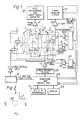
- FIGS 1 and 2 illustrate the apparatus diagrammatically
- FIG. 3 illustrates the magnetic field sequence employed in the method.
- the method is performed using an apparatus essentially identical to that described in U.K. Patent Specification No. 1,578,910 or No. 2,056,078 to which reference should be made for a fuller description, appropriately programmed to apply a sequence of magnetic field gradient and RF pulses and analyse the resulting signals as hereafter described.
- the apparatus includes a first coil system whereby a magnetic field can be applied to a body to be examined in a given direction, normally designated the Z-direction, with a gradient in any one or more of the three orthogonal directions i.e. X, Y and Z directions.
- the first coil system comprises coils 1 capable of providing a steady uniform magnetic field in the Z direction; coils 3 capable of providing a magnetic field gradient in the X direction, coils 5 capable of providing a magnetic field gradient in the Y direction; and coils 7 capable of providing a magnetic field gradient in the Z direction.
- the apparatus includes a second coil system 9 whereby RF magnetic fields can be applied to the body under examination in a plane normal to the direction of the steady uniform magnetic field produced by the first coil system, and whereby RF magnetic fields resulting from nuclei in the body under examination which have been excited to nuclear magnetic resonance with a spin vector component other than in the Z direction can be detected.
- the various coils 1, 3, 5, 7 and 9 are driven by drive amplifiers 11, 12, 13, 15, 17 and 19 respectively, controlled by control circuits 21, 23, 25 and 27 respectively.
- These circuits may take various forms which are well known to those with experience of NMR equipment and other apparatus using coil induced magnetic fields.
- the circuits 21, 23, 25 and 27 are controlled by a central processing and control unit 29 with which are associated inputs and other peripherals 31, for the provision of commands and instructions to the apparatus, and a display 33.
- the NMR signals detected by the coils 9 are applied via an amplifier 35 to a signal handling system 37.
- the signal handling system is arranged to make any appropriate calibration and correction of the signals, but essentially transmits the signals to the processing and control unit 29 wherein the signals are processed for application to the display to produce an image representing the distribution of an NMR quantity in the body being examined.
- the signal handling system 3 may conveniently form part of the unit 29.
- the apparatus also includes field measurement and error signal circuits 39 which receive signals via amplifiers 41 from field probes X 1 , X 2 , Y i and Y 2 which are disposed at suitable positions in relation to a slice 43 of the body being examined, as illustrated in Figure 2, to monitor the applied magnetic fields.
- a steady uniform magnetic field Bo is applied to the body under examination in the Z direction.
- This field serves to define the equilibrium axis of magnetic alignment of the nuclei in the body i.e. along the Z direction, and remains constant throughout the examination procedure.
- a magnetic field gradient Gz along the Z direction is then applied to the body, together with an RF magnetic field pulse denoted 8 1 (90°), for reasons explained hereafter.
- the frequency of the RF field is chosen to be the Larmor frequency for protons in a slice 43 of the body, normal to the Z direction, the slice being defined by a particular magnetic field along the Z direction, such that protons within the slice are preferentially excited, the slice consisting of an area of substantially solid material through which a series of blood vessels extend.
- the integral of the RF pulses is such that the pulse is just sufficient to tip the spins of the excited protons into the X-Y plane, and is thus referred to as a 90° pulse, the spins then preces- sing in the X-Y plane round the Z axis.
- the field gradient Gz is then removed, and replaced by a gradient in the opposite sense -Gz'.
- This causes the rephasing of the spins which have been selectively excited by the combination of the RF pulse B 1 (90°), Bo and the field gradient Gz, the dephasing having been caused by the gradient through the slice.
- the magnitude of -Gz' is adjusted so that the spins are rephased at the time at which this gradient is switched off as described, for example, in the above mentioned UK Patent Specification No. 1,57,910.
- a second RF magnetic field pulse 8 2 (90°) having the same characteristics as the B 1 (90°) pulse is applied.
- a period of time, T is then allowed to elapse, during which time the excited spins throughout the body relax back towards the positive Z direction.
- a number of pulsed magnetic field gradients Gzd may be imposed along the Z direction, these pulses causing phase dispersion of spins lying in the X-Y plane in addition to the phase dispersion of the spins which naturally occurs, due to the spin-spin interaction (T 2 effects).
- the gradients Gzd do not however affect spins in the Z directions.
- these pulses reduce the signal which would be induced in the second coil system by spins outside the selected slice which have remained in the X-Y plane although for long values of T this signal would in any case be small.
- a third RF magnetic field pulse 8 3 again having the same characteristics as the B 1 (90°) pulse is applied in the presence of the magnetic field gradient to selectively excite the protons within the slice as before, this sequence again being followed by the rephasing gradient -Gz'.
- the signal induced in the second coil signal by these spins, i.e. the Free Induction Decay (F.I.D.) system 9 is then recorded, the spins outside the slice which remain in the XY plane after the period having been dephased as explained herebefore, and thus not contributing significantly to the measured signal.
- F.I.D. Free Induction Decay
- the magnitude of the measured F.I.D. signal is related to the density of protons within the slice, and will consist of contributions from hydrogen protons in three different circumstances:
- the net contribution to the measured signal will be As in practice the whole pulse sequence is repeated several times, there will be a further contribution to the signal originating from the hydrogen protons in the solid material in the slice of the form where t d is the time which has passed between the 8 1 (90°) pulses in each pair of sequences, to compensate for the spins not being in their equilibrium condition i.e. aligned along the positive Z direction, at the beginning of each pulse sequence.
- t d is the time which has passed between the 8 1 (90°) pulses in each pair of sequences, to compensate for the spins not being in their equilibrium condition i.e. aligned along the positive Z direction, at the beginning of each pulse sequence.
- the total contribution ⁇ 1 to the measured F.I.D. signal from the solid material in the slice will be of the form: i.e. the usual form of expression for inversion recovery experiments.
- the choise of the time T is determined by the values of the spin-lattice relaxation times T 1s and Tie. As these times can for many tissues be relatively long, in the order of 400 ms, relatively slow flow rates can readily be monitored by this method. Due to the long time periods available the magnitude of the applied gradients can be minimised, and thus the resonance signal from excited spins within the body are dispersed relatively slowly. The F.I.D. signal will then persist above noise levels for longer, and also sharp resonance lines will be maintained. This is particularly advantageous where it is desired to also measure the chemical shift in the Larmor frequency between for example, protons in the blood and protons in the solid material in the slice.
Landscapes
- Health & Medical Sciences (AREA)
- Physics & Mathematics (AREA)
- Life Sciences & Earth Sciences (AREA)
- General Physics & Mathematics (AREA)
- Nuclear Medicine, Radiotherapy & Molecular Imaging (AREA)
- Engineering & Computer Science (AREA)
- General Health & Medical Sciences (AREA)
- Veterinary Medicine (AREA)
- Heart & Thoracic Surgery (AREA)
- Condensed Matter Physics & Semiconductors (AREA)
- Vascular Medicine (AREA)
- Hematology (AREA)
- Cardiology (AREA)
- Physiology (AREA)
- Signal Processing (AREA)
- Radiology & Medical Imaging (AREA)
- Molecular Biology (AREA)
- Biomedical Technology (AREA)
- High Energy & Nuclear Physics (AREA)
- Medical Informatics (AREA)
- Pathology (AREA)
- Surgery (AREA)
- Animal Behavior & Ethology (AREA)
- Public Health (AREA)
- Biophysics (AREA)
- Fluid Mechanics (AREA)
- Magnetic Resonance Imaging Apparatus (AREA)
- Measuring Volume Flow (AREA)
Claims (8)
Applications Claiming Priority (2)
| Application Number | Priority Date | Filing Date | Title |
|---|---|---|---|
| GB8223862 | 1982-08-19 | ||
| GB8223862 | 1982-08-19 |
Publications (3)
| Publication Number | Publication Date |
|---|---|
| EP0103388A2 EP0103388A2 (de) | 1984-03-21 |
| EP0103388A3 EP0103388A3 (en) | 1986-05-14 |
| EP0103388B1 true EP0103388B1 (de) | 1988-11-17 |
Family
ID=10532396
Family Applications (1)
| Application Number | Title | Priority Date | Filing Date |
|---|---|---|---|
| EP83304483A Expired EP0103388B1 (de) | 1982-08-19 | 1983-08-03 | Kernmagnetische Resonanzmethode und Vorrichtung |
Country Status (5)
| Country | Link |
|---|---|
| US (1) | US4587488A (de) |
| EP (1) | EP0103388B1 (de) |
| JP (1) | JPS5960262A (de) |
| DE (1) | DE3378495D1 (de) |
| GB (1) | GB2125562B (de) |
Families Citing this family (14)
| Publication number | Priority date | Publication date | Assignee | Title |
|---|---|---|---|---|
| US4564813A (en) * | 1982-11-10 | 1986-01-14 | Picker International, Ltd. | Nuclear magnetic resonance method and apparatus |
| US4516075A (en) * | 1983-01-04 | 1985-05-07 | Wisconsin Alumni Research Foundation | NMR scanner with motion zeugmatography |
| JPS6039539A (ja) * | 1983-08-15 | 1985-03-01 | Hitachi Ltd | 核磁気共鳴を用いた検査装置 |
| IL74942A (en) * | 1984-10-22 | 1988-11-30 | Univ Leland Stanford Junior | Flow measurement using nuclear magnetic resonance |
| GB8521791D0 (en) * | 1985-09-02 | 1985-10-09 | Picker Int Ltd | Nuclear magnetic resonance imaging |
| US4697149A (en) * | 1985-11-04 | 1987-09-29 | Wisconsin Alumni Research Foundation | NMR flow imaging using a composite excitation field and magnetic field gradient sequence |
| IL79076A (en) * | 1986-06-10 | 1989-10-31 | Elscint Ltd | Restricted volume imaging |
| FI874419L (fi) * | 1987-10-08 | 1989-04-09 | Instrumentarium Oy | Anordning och foerfarande foer undersoekning av ett objekts egenskaper. |
| IL84152A (en) * | 1987-10-12 | 1991-06-10 | Elscint Ltd | Magnetic resonance spectroscopic measurements of restricted volumes |
| US6272370B1 (en) | 1998-08-07 | 2001-08-07 | The Regents Of University Of Minnesota | MR-visible medical device for neurological interventions using nonlinear magnetic stereotaxis and a method imaging |
| US6463317B1 (en) | 1998-05-19 | 2002-10-08 | Regents Of The University Of Minnesota | Device and method for the endovascular treatment of aneurysms |
| RU2256931C1 (ru) * | 2004-02-24 | 2005-07-20 | Открытое акционерное общество "Альметьевский завод "Радиоприбор" | Устройство для измерения состава и расхода многокомпонентной жидкости на основе ядерного магнитного резонанса (варианты) |
| RU2544360C1 (ru) * | 2013-12-04 | 2015-03-20 | Федеральное государственное бюджетное образовательное учреждение высшего профессионального образования "Казанский государственный энергетический университет" (ФГБОУ ВПО "КГЭУ") | Устройство для измерения состава и расхода многокомпонентных жидкостей методом ядерного магнитного резонанса |
| CN103969604B (zh) * | 2014-05-30 | 2017-03-15 | 华南师范大学 | 射频原子磁力仪及其测量核磁共振信号的方法 |
Citations (1)
| Publication number | Priority date | Publication date | Assignee | Title |
|---|---|---|---|---|
| EP0103372A2 (de) * | 1982-08-11 | 1984-03-21 | Picker International Limited | Kernmagnetische Resonanzmethode und -Vorrichtung |
Family Cites Families (5)
| Publication number | Priority date | Publication date | Assignee | Title |
|---|---|---|---|---|
| JPS49103693A (de) * | 1973-02-02 | 1974-10-01 | ||
| US4458203A (en) * | 1980-12-11 | 1984-07-03 | Picker International Limited | Nuclear magnetic resonance imaging |
| US4528985A (en) * | 1981-12-21 | 1985-07-16 | Albert Macovski | Blood vessel imaging system using nuclear magnetic resonance |
| US4516075A (en) * | 1983-01-04 | 1985-05-07 | Wisconsin Alumni Research Foundation | NMR scanner with motion zeugmatography |
| US4516582A (en) * | 1983-05-02 | 1985-05-14 | General Electric Company | NMR blood flow imaging |
-
1983
- 1983-08-03 GB GB08320946A patent/GB2125562B/en not_active Expired
- 1983-08-03 DE DE8383304483T patent/DE3378495D1/de not_active Expired
- 1983-08-03 EP EP83304483A patent/EP0103388B1/de not_active Expired
- 1983-08-03 US US06/519,832 patent/US4587488A/en not_active Expired - Fee Related
- 1983-08-19 JP JP58151464A patent/JPS5960262A/ja active Pending
Patent Citations (1)
| Publication number | Priority date | Publication date | Assignee | Title |
|---|---|---|---|---|
| EP0103372A2 (de) * | 1982-08-11 | 1984-03-21 | Picker International Limited | Kernmagnetische Resonanzmethode und -Vorrichtung |
Also Published As
| Publication number | Publication date |
|---|---|
| EP0103388A2 (de) | 1984-03-21 |
| US4587488A (en) | 1986-05-06 |
| JPS5960262A (ja) | 1984-04-06 |
| EP0103388A3 (en) | 1986-05-14 |
| GB2125562B (en) | 1985-11-20 |
| GB2125562A (en) | 1984-03-07 |
| GB8320946D0 (en) | 1983-09-07 |
| DE3378495D1 (en) | 1988-12-22 |
Similar Documents
| Publication | Publication Date | Title |
|---|---|---|
| US4563647A (en) | Nuclear magnetic resonance methods and apparatus | |
| US4520828A (en) | Nuclear magnetic resonance method and apparatus | |
| EP0103388B1 (de) | Kernmagnetische Resonanzmethode und Vorrichtung | |
| EP0100183B1 (de) | Kernmagnetische Resonanzmethode und Vorrichtung | |
| US4558278A (en) | Nuclear magnetic resonance methods and apparatus | |
| US4733183A (en) | Nuclear magnetic resonance methods and apparatus | |
| US4642568A (en) | Nuclear magnetic resonance methods and apparatus | |
| US4564813A (en) | Nuclear magnetic resonance method and apparatus | |
| US4631480A (en) | Nuclear magnetic resonance method and apparatus | |
| EP0106472B1 (de) | Magnetische Kernresonanzmethode und -vorrichtung | |
| EP0217578B1 (de) | Verfahren und Apparatur zur kernmagnetischen Resonanz | |
| GB2127155A (en) | Flow determination by nuclear magnetic resonance | |
| US4703269A (en) | Nuclear magnetic resonance imaging methods and apparatus | |
| EP0129356A2 (de) | Magnetische Kernresonanzmethode und Vorrichtung | |
| Burl et al. | Nuclear magnetic resonance method and apparatus | |
| Young | Nuclear magnetic resonance method and apparatus |
Legal Events
| Date | Code | Title | Description |
|---|---|---|---|
| PUAI | Public reference made under article 153(3) epc to a published international application that has entered the european phase |
Free format text: ORIGINAL CODE: 0009012 |
|
| AK | Designated contracting states |
Designated state(s): DE FR NL |
|
| PUAL | Search report despatched |
Free format text: ORIGINAL CODE: 0009013 |
|
| AK | Designated contracting states |
Kind code of ref document: A3 Designated state(s): DE FR NL |
|
| 17P | Request for examination filed |
Effective date: 19860616 |
|
| 17Q | First examination report despatched |
Effective date: 19880222 |
|
| GRAA | (expected) grant |
Free format text: ORIGINAL CODE: 0009210 |
|
| AK | Designated contracting states |
Kind code of ref document: B1 Designated state(s): DE FR NL |
|
| REF | Corresponds to: |
Ref document number: 3378495 Country of ref document: DE Date of ref document: 19881222 |
|
| ET | Fr: translation filed | ||
| PLBE | No opposition filed within time limit |
Free format text: ORIGINAL CODE: 0009261 |
|
| STAA | Information on the status of an ep patent application or granted ep patent |
Free format text: STATUS: NO OPPOSITION FILED WITHIN TIME LIMIT |
|
| 26N | No opposition filed | ||
| PGFP | Annual fee paid to national office [announced via postgrant information from national office to epo] |
Ref country code: FR Payment date: 19950717 Year of fee payment: 13 |
|
| PGFP | Annual fee paid to national office [announced via postgrant information from national office to epo] |
Ref country code: NL Payment date: 19950830 Year of fee payment: 13 |
|
| PGFP | Annual fee paid to national office [announced via postgrant information from national office to epo] |
Ref country code: DE Payment date: 19951025 Year of fee payment: 13 |
|
| PG25 | Lapsed in a contracting state [announced via postgrant information from national office to epo] |
Ref country code: NL Effective date: 19970301 |
|
| PG25 | Lapsed in a contracting state [announced via postgrant information from national office to epo] |
Ref country code: FR Effective date: 19970430 |
|
| NLV4 | Nl: lapsed or anulled due to non-payment of the annual fee |
Effective date: 19970301 |
|
| PG25 | Lapsed in a contracting state [announced via postgrant information from national office to epo] |
Ref country code: DE Effective date: 19970501 |
|
| REG | Reference to a national code |
Ref country code: FR Ref legal event code: ST |