EP0103687B1 - Support de cliché pour machines d'impression à tampon d'encrage - Google Patents
Support de cliché pour machines d'impression à tampon d'encrage Download PDFInfo
- Publication number
- EP0103687B1 EP0103687B1 EP83106687A EP83106687A EP0103687B1 EP 0103687 B1 EP0103687 B1 EP 0103687B1 EP 83106687 A EP83106687 A EP 83106687A EP 83106687 A EP83106687 A EP 83106687A EP 0103687 B1 EP0103687 B1 EP 0103687B1
- Authority
- EP
- European Patent Office
- Prior art keywords
- printing block
- receiver
- printing
- base member
- holder according
- Prior art date
- Legal status (The legal status is an assumption and is not a legal conclusion. Google has not performed a legal analysis and makes no representation as to the accuracy of the status listed.)
- Expired
Links
- 238000007639 printing Methods 0.000 title claims abstract description 33
- 238000007789 sealing Methods 0.000 claims description 4
- 238000007649 pad printing Methods 0.000 abstract description 5
- 239000011248 coating agent Substances 0.000 abstract 1
- 238000000576 coating method Methods 0.000 abstract 1
- 238000005259 measurement Methods 0.000 abstract 1
- 239000013508 solvent resistant sealant Substances 0.000 abstract 1
- 238000010276 construction Methods 0.000 description 2
- 230000000630 rising effect Effects 0.000 description 2
- 239000002904 solvent Substances 0.000 description 2
- 230000006978 adaptation Effects 0.000 description 1
- 238000013459 approach Methods 0.000 description 1
- 230000007704 transition Effects 0.000 description 1
Images

Classifications
-
- B—PERFORMING OPERATIONS; TRANSPORTING
- B41—PRINTING; LINING MACHINES; TYPEWRITERS; STAMPS
- B41F—PRINTING MACHINES OR PRESSES
- B41F17/00—Printing apparatus or machines of special types or for particular purposes, not otherwise provided for
- B41F17/001—Pad printing apparatus or machines
-
- B—PERFORMING OPERATIONS; TRANSPORTING
- B41—PRINTING; LINING MACHINES; TYPEWRITERS; STAMPS
- B41F—PRINTING MACHINES OR PRESSES
- B41F27/00—Devices for attaching printing elements or formes to supports
- B41F27/08—Devices for attaching printing elements or formes to supports for attaching printing formes to flat type-beds
Definitions
- the invention relates to a plate holder for pad printing machines with a plate-shaped base body, which has a recessed ink reservoir on its top parallel to the back and in the area lying in front of the ink reservoir has a receptacle with clamping devices that is matched to the dimensions of the plate.
- a pad printing machine using such plate holders is described in DE-AS 1 939437 and FR-A 2388679. It is aligned with each other in the top of the base body, the ink reservoir and the plate holder are simply recessed as recessed recesses.
- the dimensions of the cliché holder are precisely matched to the dimensions of the cliché. This configuration of the plate holder therefore means that a separate plate holder is required for each plate size. With a large number of different sizes of the clichés, this is a considerable effort and, in addition, when changing the cliché there is usually also the change of the cliché holder, which also results in unnecessarily long changeover times.
- the ink supply pan and the plate holder each have a constant cross-section over the entire width of the base body and that the width of the ink tank and plate holder can be limited to the width of the plate used by means of two clamping strips, the Bottom sides of the terminal strips are designed for the contour of the top of the base body and are provided with a flexible, solvent-resistant sealing layer.
- the base body is designed so that it can be adjusted to any width of clichés using the two adjustable clamping bars.
- the terminal strips seal the variable ink supply tray, which is automatically adjusted to the size of the clichés used.
- a clear sealing and setting of the cliché in the area of the top of the base body is obtained in that the cliché holder is groove-shaped and has a depth that is greater than the thickness of the clichés used, that pressure bolts are arranged in the bottom of the cliché holder, which are adjustable by means of set screws against the clichés, that the top of the cliché is flush with the upper sides of the adjacent groove walls of the cliché holder and that the clamping strips in the area of the cliché cover and seal the edges of the cliché.
- a continuous height adjustment of the pressure bolts when the plate holder is mounted in the tampon printing machine is made possible according to one embodiment in that the pressure bolts have a transverse wedge receptacle into which a wedge tip of an adjusting screw can be inserted and that the adjusting screws can be screwed into threaded receptacles of the base body, which are screwed into the front of the base body Basic body are embedded horizontally.
- a simple adaptation of the cliché holder to different dimensions in the depth of the base body is achieved according to one embodiment in that the ink supply trough is trapezoidal in cross-section and that the wall of the ink supply trough facing the cliché holder is designed as a bar that can be adjusted in depth with the base body the wall facing away from the ink reservoir forms the groove wall of the plate holder.
- the bracing of the cliché used in the cliché holder is achieved according to one embodiment in that the groove wall of the cliché holder facing away from the ink reservoir is formed by means of a profile strip attached to the front, which forms a receptacle with the groove bottom and partially covers the facing edge of the cliché used and that the profile bar receives a pressure bar in the receptacle formed, which can be clamped against the cliché used by means of pressure screws adjustable in the profile bar.
- the terminal strips have recessed receptacles for fastening screws at the ends, that the terminal strips enclose the front and rear of the base body by means of flanges, and that the fastening screws in thread receptacles of clamping blocks can be screwed in, which engage behind the underside of the base body.
- a further embodiment provides that the base body has a continuous receiving groove on the underside in the region of the front and rear, into which guide approaches of the clamping blocks engage.
- the grooves of the base body and the guide lugs of the clamping blocks are designed as halves of a dovetail connection.
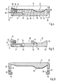
- the plate holder according to the invention has a plate-shaped base body 10.
- a color supply pan 21 with a trapezoidal cross section is continuously introduced, as can be seen from the walls 11 and 23 and the bottom 22.
- the plate holder 35 is also continuously inserted in front of this continuous ink supply tank 21, the area of the base body 10 which forms the wall 11 for the ink supply tank 21 also forming a groove wall of the groove-shaped plate holder 35.
- the depth of the plate holder 35 is greater than the thickness of the plate.
- the cliché 20 used as indicated in FIG. 2, can have different widths with the same dimensions in the depth of the base body 10, as the clichés 20 'and 20 "shown in dashed lines indicate.
- the front groove wall of the plate holder 35 is not formed by the base body 10.
- a profile strip 16 is attached to the front of the base body 10, which partially covers the plate holder 35 and itself forms a holder for pressure strips 12.
- These pressure strips 12 form the groove wall of the groove-shaped plate holder 35 and can be adjusted by means of the pressure screws 15 adjustable in the profile strip 16.
- the plate 20 used can thus be clamped against the fixed rear groove wall of the plate holder 35. Before this, the plate 20 is adjusted in height by means of the pressure bolts 13 arranged in the bottom of the plate holder 35 such that the upper side of the plate 20 is flush with the upper side of the wall 11 and the rising surface of the profile strip 16.
- the pressure bolts 13 are provided with a transverse wedge receptacle 26, into which a wedge tip of the set screw 14 is inserted.
- the set screws 14 are screwed into threaded receptacles 27 of the base body 10, which are introduced horizontally into the front of the base body 10.
- the profile strip 16 has bores 31 which allow access to the threaded receptacles 27.
- the pressure pins 13 can be adjusted in height from the front of a plate holder fixed in the pad printing machine. Only the set screws 14 need to be screwed more or less into the threaded receptacles 27.
- the wedge tips of the adjusting screws 14 inserted into the wedge receptacles 26 of the pressure bolts 13 then raise the pressure bolts 13 more or less accordingly.
- the cliché 20 lying on the pressure pin 13 is adjusted accordingly.
- the wall 11 of the ink supply trough 21 can also be part of a strip which can be fixed at different distances from the front of the base body 10.
- the plate holder 35 can thus also be adapted in the depth of the base body 10 to different dimensions of the plate 20 'and 20 ". In many cases it has proven sufficient if the bar can be adjusted in stages 5 are attached to the underside of the bar and the base body 10 carries recess 25 for these projections 24 at different distances from the front in the top side. The rest of the construction of the printing plate holder according to FIG. 5 does not differ from the construction of the printing plate holder according to FIG and 3.
- the width of the ink supply tray 21 is automatically adapted to the width of the cliché 20 used by means of two clamping strips 17 according to FIGS. 3 and 6.
- the undersides of the terminal strips 17, which carry a flexible, solvent-resistant sealing layer 19, are matched to the contour of the upper side of the base body 10. Therefore, the continuous ink supply pan 21 is closed on both sides by the terminal strips 17.
- the clamping strips 17 cover the edges of the plate 20 and therefore seal in the area of the top of the plate 20, as can be seen from the section according to FIG. 4.
- the flush transition from the cliché 20 to the wall 11 and to the rising part of the profile strip 16 is ensured and a clear seal is ensured.
- the clamping strips 17 encompass the base body 10 with the flanges 34. Stepped receptacles 28 for the fastening screws 30 are introduced into the flanges 34.
- the fastening screws 30 can be screwed into the threaded receptacles 29 of clamping blocks 18.
- the clamping blocks 18 carry guide lugs 36 which engage in receiving grooves 33 on the underside of the base body 10. These receiving grooves 33 are continuously attached to the front and rear, so that the clamping strips 17 can easily be moved to any position on the base body 10 when the fastening screws 30 are loosened.
- the receiving grooves 33 of the base body 10 and the guide lugs 36 of the clamping blocks 18 form halves of dovetail connections in the exemplary embodiment.
Landscapes
- Inking, Control Or Cleaning Of Printing Machines (AREA)
- Packaging Of Annular Or Rod-Shaped Articles, Wearing Apparel, Cassettes, Or The Like (AREA)
- Printing Plates And Materials Therefor (AREA)
- Screen Printers (AREA)
Claims (9)
Priority Applications (1)
| Application Number | Priority Date | Filing Date | Title |
|---|---|---|---|
| AT83106687T ATE26673T1 (de) | 1982-07-28 | 1983-07-08 | Klischeehalter fuer tampondruckmaschinen. |
Applications Claiming Priority (2)
| Application Number | Priority Date | Filing Date | Title |
|---|---|---|---|
| DE3228152A DE3228152C2 (de) | 1982-07-28 | 1982-07-28 | Klischeehalter für Tampondruckmaschinen |
| DE3228152 | 1982-07-28 |
Publications (3)
| Publication Number | Publication Date |
|---|---|
| EP0103687A2 EP0103687A2 (fr) | 1984-03-28 |
| EP0103687A3 EP0103687A3 (en) | 1985-09-25 |
| EP0103687B1 true EP0103687B1 (fr) | 1987-04-22 |
Family
ID=6169509
Family Applications (1)
| Application Number | Title | Priority Date | Filing Date |
|---|---|---|---|
| EP83106687A Expired EP0103687B1 (fr) | 1982-07-28 | 1983-07-08 | Support de cliché pour machines d'impression à tampon d'encrage |
Country Status (5)
| Country | Link |
|---|---|
| US (1) | US4491072A (fr) |
| EP (1) | EP0103687B1 (fr) |
| JP (1) | JPS5924674A (fr) |
| AT (1) | ATE26673T1 (fr) |
| DE (1) | DE3228152C2 (fr) |
Families Citing this family (4)
| Publication number | Priority date | Publication date | Assignee | Title |
|---|---|---|---|---|
| DE8331501U1 (de) * | 1983-11-03 | 1984-02-02 | TAMPOflex GmbH, 7257 Ditzingen | Farbgeber fuer eine tampondruckmaschine |
| JPH037158Y2 (fr) * | 1985-05-07 | 1991-02-22 | ||
| DE4236192A1 (fr) * | 1992-01-09 | 1993-07-15 | Martin Grube | |
| KR20140008250A (ko) * | 2012-07-10 | 2014-01-21 | 주식회사 엘지화학 | 피인쇄물 고정구, 인쇄 장치 및 인쇄 방법 |
Family Cites Families (8)
| Publication number | Priority date | Publication date | Assignee | Title |
|---|---|---|---|---|
| US764517A (en) * | 1901-12-28 | 1904-07-05 | P R Rideout | Stereotype-block. |
| DE489851C (de) * | 1927-10-27 | 1930-01-20 | Chester B Johnson | Stuetzleiste zum Befestigen des Satzes auf dem Fundament von Zylinderschnellpressen |
| US1721458A (en) * | 1928-05-11 | 1929-07-16 | Macdonald William | Inking attachment for color printing |
| US2373491A (en) * | 1942-11-24 | 1945-04-10 | Murray John | Mechanized mount for the assembly of flat printing plates |
| US4060031A (en) * | 1969-08-02 | 1977-11-29 | Wilfried Philipp | Printing method and apparatus for performing the printing method |
| CH522507A (fr) * | 1971-02-04 | 1972-06-30 | Schmid Pierre | Appareil pour l'encrage d'un cliché d'impression |
| FR2388679A1 (fr) * | 1977-04-28 | 1978-11-24 | Cer Sa Ets | Perfectionnements aux machines d'impression par tampographie |
| FR2408464A1 (fr) * | 1977-11-09 | 1979-06-08 | Brenot Claude | Dispositif d'impression par report au coussin |
-
1982
- 1982-07-28 DE DE3228152A patent/DE3228152C2/de not_active Expired
-
1983
- 1983-07-08 EP EP83106687A patent/EP0103687B1/fr not_active Expired
- 1983-07-08 AT AT83106687T patent/ATE26673T1/de not_active IP Right Cessation
- 1983-07-12 JP JP58125633A patent/JPS5924674A/ja active Pending
- 1983-07-28 US US06/518,019 patent/US4491072A/en not_active Expired - Fee Related
Also Published As
| Publication number | Publication date |
|---|---|
| EP0103687A3 (en) | 1985-09-25 |
| DE3228152C2 (de) | 1984-12-06 |
| DE3228152A1 (de) | 1984-02-02 |
| US4491072A (en) | 1985-01-01 |
| JPS5924674A (ja) | 1984-02-08 |
| ATE26673T1 (de) | 1987-05-15 |
| EP0103687A2 (fr) | 1984-03-28 |
Similar Documents
| Publication | Publication Date | Title |
|---|---|---|
| EP0374092B1 (fr) | Encrier pour machine d'impression | |
| DE2324755A1 (de) | Gestell zur aufnahme von verbindungskaesten von gedruckten schaltungskarten | |
| CH630282A5 (de) | Messerwelle fuer holzzerspanungsmaschinen. | |
| EP0374710A2 (fr) | Dispositif d'encrage à racle | |
| DE3902599C2 (de) | Vorrichtung zum Streichen einer Papierbahn mit einer Beschichtungsmasse | |
| EP0103687B1 (fr) | Support de cliché pour machines d'impression à tampon d'encrage | |
| DE1752540A1 (de) | Polierwerkzeug zur Oberflaechenbehandlung von stetig bewegten Glasbaendern | |
| EP0453872B1 (fr) | Dispositif de lames d'encrier | |
| DE3209246C2 (de) | Messerträger eines Hobelmessers | |
| DE3604963A1 (de) | Einsatz zum unterteilen einer giessform | |
| DE3611446C2 (fr) | ||
| EP0253382A1 (fr) | Dispositif d'encollage pour étiqueteuses | |
| EP0445363A1 (fr) | Dispositif de fraisage ou perçage | |
| DE3637985C2 (de) | Biegestanze | |
| EP0479266B1 (fr) | Dispositif de soutien dans l'évidement d'un cylindre | |
| DE8221449U1 (de) | Klischeehalter fuer tampondruckmaschinen | |
| WO1997048087A1 (fr) | Support pour panneaux pivotants ou similaire | |
| DE414325C (de) | Farbwerk fuer Plattendruckmaschinen | |
| DE8911268U1 (de) | Richtapparat zur Geraderichten von abspulbaren Endlosmaterialien | |
| DE7441924U (de) | Verschlussschiebervorrichtung fuer feuerfeste behaelter | |
| DE9413049U1 (de) | Vorrichtung zum Befestigen einer Abdeckleiste für Nuten von Kraftwagen-Aufbauten | |
| EP2942138A1 (fr) | Guidage pour un ruban d'une scie | |
| DE29815560U1 (de) | Einrichtung zum Längsteilen von Materialbahnen mit verschieb- und festlegbaren Schneideinrichtungen | |
| DE9013781U1 (de) | Tellerbesen für eine Kehrmaschine | |
| DE3927238A1 (de) | Haushaltgeraet, z.b. geschirrspuelmaschine |
Legal Events
| Date | Code | Title | Description |
|---|---|---|---|
| PUAI | Public reference made under article 153(3) epc to a published international application that has entered the european phase |
Free format text: ORIGINAL CODE: 0009012 |
|
| AK | Designated contracting states |
Designated state(s): AT BE CH FR GB IT LI LU NL SE |
|
| PUAL | Search report despatched |
Free format text: ORIGINAL CODE: 0009013 |
|
| AK | Designated contracting states |
Designated state(s): AT BE CH FR GB IT LI LU NL SE |
|
| 17P | Request for examination filed |
Effective date: 19850917 |
|
| 17Q | First examination report despatched |
Effective date: 19861007 |
|
| GRAA | (expected) grant |
Free format text: ORIGINAL CODE: 0009210 |
|
| AK | Designated contracting states |
Kind code of ref document: B1 Designated state(s): AT BE CH FR GB IT LI LU NL SE |
|
| PG25 | Lapsed in a contracting state [announced via postgrant information from national office to epo] |
Ref country code: NL Effective date: 19870422 Ref country code: IT Free format text: LAPSE BECAUSE OF FAILURE TO SUBMIT A TRANSLATION OF THE DESCRIPTION OR TO PAY THE FEE WITHIN THE PRESCRIBED TIME-LIMIT;WARNING: LAPSES OF ITALIAN PATENTS WITH EFFECTIVE DATE BEFORE 2007 MAY HAVE OCCURRED AT ANY TIME BEFORE 2007. THE CORRECT EFFECTIVE DATE MAY BE DIFFERENT FROM THE ONE RECORDED. Effective date: 19870422 Ref country code: FR Free format text: THE PATENT HAS BEEN ANNULLED BY A DECISION OF A NATIONAL AUTHORITY Effective date: 19870422 Ref country code: BE Effective date: 19870422 |
|
| REF | Corresponds to: |
Ref document number: 26673 Country of ref document: AT Date of ref document: 19870515 Kind code of ref document: T |
|
| PG25 | Lapsed in a contracting state [announced via postgrant information from national office to epo] |
Ref country code: SE Effective date: 19870430 |
|
| PG25 | Lapsed in a contracting state [announced via postgrant information from national office to epo] |
Ref country code: AT Effective date: 19870708 |
|
| PG25 | Lapsed in a contracting state [announced via postgrant information from national office to epo] |
Ref country code: LU Free format text: LAPSE BECAUSE OF NON-PAYMENT OF DUE FEES Effective date: 19870731 Ref country code: LI Effective date: 19870731 Ref country code: CH Effective date: 19870731 |
|
| EN | Fr: translation not filed | ||
| NLV1 | Nl: lapsed or annulled due to failure to fulfill the requirements of art. 29p and 29m of the patents act | ||
| PLBE | No opposition filed within time limit |
Free format text: ORIGINAL CODE: 0009261 |
|
| STAA | Information on the status of an ep patent application or granted ep patent |
Free format text: STATUS: NO OPPOSITION FILED WITHIN TIME LIMIT |
|
| REG | Reference to a national code |
Ref country code: CH Ref legal event code: PL |
|
| 26N | No opposition filed | ||
| PG25 | Lapsed in a contracting state [announced via postgrant information from national office to epo] |
Ref country code: GB Effective date: 19880708 |
|
| GBPC | Gb: european patent ceased through non-payment of renewal fee |