EP0103708A1 - Buse annulaire et son utilisation dans des sécheurs à lit fluide - Google Patents
Buse annulaire et son utilisation dans des sécheurs à lit fluide Download PDFInfo
- Publication number
- EP0103708A1 EP0103708A1 EP83107424A EP83107424A EP0103708A1 EP 0103708 A1 EP0103708 A1 EP 0103708A1 EP 83107424 A EP83107424 A EP 83107424A EP 83107424 A EP83107424 A EP 83107424A EP 0103708 A1 EP0103708 A1 EP 0103708A1
- Authority
- EP
- European Patent Office
- Prior art keywords
- annular gap
- compact
- flow
- nozzle according
- gap nozzle
- Prior art date
- Legal status (The legal status is an assumption and is not a legal conclusion. Google has not performed a legal analysis and makes no representation as to the accuracy of the status listed.)
- Granted
Links
- 239000012530 fluid Substances 0.000 title claims abstract description 13
- 230000000295 complement effect Effects 0.000 claims abstract description 4
- 230000007423 decrease Effects 0.000 claims description 2
- 230000000694 effects Effects 0.000 description 4
- 238000011161 development Methods 0.000 description 2
- 230000018109 developmental process Effects 0.000 description 2
- 238000004519 manufacturing process Methods 0.000 description 2
- 230000002349 favourable effect Effects 0.000 description 1
- 239000008188 pellet Substances 0.000 description 1
- 239000000725 suspension Substances 0.000 description 1
Images
Classifications
-
- B—PERFORMING OPERATIONS; TRANSPORTING
- B05—SPRAYING OR ATOMISING IN GENERAL; APPLYING FLUENT MATERIALS TO SURFACES, IN GENERAL
- B05B—SPRAYING APPARATUS; ATOMISING APPARATUS; NOZZLES
- B05B1/00—Nozzles, spray heads or other outlets, with or without auxiliary devices such as valves, heating means
- B05B1/26—Nozzles, spray heads or other outlets, with or without auxiliary devices such as valves, heating means with means for mechanically breaking-up or deflecting the jet after discharge, e.g. with fixed deflectors; Breaking-up the discharged liquid or other fluent material by impinging jets
- B05B1/262—Nozzles, spray heads or other outlets, with or without auxiliary devices such as valves, heating means with means for mechanically breaking-up or deflecting the jet after discharge, e.g. with fixed deflectors; Breaking-up the discharged liquid or other fluent material by impinging jets with fixed deflectors
- B05B1/265—Nozzles, spray heads or other outlets, with or without auxiliary devices such as valves, heating means with means for mechanically breaking-up or deflecting the jet after discharge, e.g. with fixed deflectors; Breaking-up the discharged liquid or other fluent material by impinging jets with fixed deflectors the liquid or other fluent material being symmetrically deflected about the axis of the nozzle
-
- B—PERFORMING OPERATIONS; TRANSPORTING
- B01—PHYSICAL OR CHEMICAL PROCESSES OR APPARATUS IN GENERAL
- B01J—CHEMICAL OR PHYSICAL PROCESSES, e.g. CATALYSIS OR COLLOID CHEMISTRY; THEIR RELEVANT APPARATUS
- B01J8/00—Chemical or physical processes in general, conducted in the presence of fluids and solid particles; Apparatus for such processes
- B01J8/18—Chemical or physical processes in general, conducted in the presence of fluids and solid particles; Apparatus for such processes with fluidised particles
- B01J8/24—Chemical or physical processes in general, conducted in the presence of fluids and solid particles; Apparatus for such processes with fluidised particles according to "fluidised-bed" technique
- B01J8/44—Fluidisation grids
Definitions
- the invention relates to an annular gap nozzle on a floor for distributing a flowing medium over this floor, which has an axial channel passing through the floor, which is covered with a cap, leaving an annular gap between the cap and the floor, the cap being by means of a through through the channel and coaxial to it, held in a holder attached in the flow direction of the medium at the beginning of the channel holder, whereby a flow space is formed in which the axial flow of the medium in the channel area is deflected in a deflection space and through which Annular gap flows out, with all the walls delimiting the flow space being drawn in such a way that the cross section of the flow-through area of the annular flow space decreases continuously in the direction of the flow of the medium towards the exit edge of the annular gap, at least in the deflection space of the flow space.
- annular gap nozzles for example described in GB 2 015 377, are used for example in fluid bed dryers and serve to introduce a medium which keeps the granular product introduced into the fluid bed dryer in suspension. Due to the special design of this annular gap nozzle, the inflowing medium is directed towards the bottom of the fluid bed dryer so that the product cannot settle on the bottom of the fluid bed dryer.
- a disadvantage of such known annular gap nozzles is that when the medium flow is switched off, the product located in the fluid bed dryer can flow into the nozzles. Since the deflection of the medium flow in these annular gap nozzles is at most 90 °, or is just below it, the bottom of the dryer is not yet ideally swept by the medium flow and the effect is not yet optimal. In order to close the known annular gap nozzles if necessary, the upper part of the nozzle usually has to be screwed in from the inside of the dryer and therefore requires complicated manipulation. Known annular gap nozzles are also not easy and inexpensive to manufacture.
- the object of the invention is to avoid the disadvantages of the prior art mentioned and, in particular, to create an annular gap nozzle which is uncomplicated, simple and inexpensive to manufacture and which avoids product backflow when the medium is switched off, in which the flow is increased by more than 90 ° can be deflected and which can be closed in a simple manner and acts as a valve.
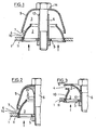
- the invention is characterized in that the flow space, i.e. the channel and the deflection space are delimited by walls of two mutually complementary and nested bowl-shaped compacts, which are arranged in the region of a hole through the floor and are kept at a distance from one another.
- annular gap nozzle can be used with particular advantage at the bottom of a fluid bed dryer.
- a bore 11 is provided in the bottom 1 of a fluid bed dryer for the inlet of a medium, for example air or steam, into the interior of the fluid bed dryer.
- a medium for example air or steam
- a flow space is formed here, which consists of a channel 2 inside the lower pellet 10 and a subsequent deflection space 3 inside the upper compact.
- the upper compact 9 has a somewhat larger diameter than the bore 11.
- the lower compact 10 is expediently pressed into the bore 11 and is thus fixed immovably in it. In a development of the invention, however, the lower compact 10 can also be arranged displaceably in the bore 11.
- the lower compact 10 also has a holder 5 with which the upper compact 9 is held by means of a connecting part 6.
- annular gap 4 is thus formed, through which the inflowing medium is directed at an increased speed and with deflection by more than 90 ° onto the bottom 1 of the fluid bed dryer and prevents settling of the processed product . Since the deflection is greater than in the case of previously known annular gap nozzles, such an arrangement is particularly effective. Furthermore, the nesting of the two compacts 9 and 10 and their complementary design prevent the product from flowing into the deflection space 3 when the medium flow is switched off and clogging the supply lines. This advantageous effect is achieved with a particularly simple design of the two compacts and a very simple assembly.
- the annular gap nozzle described also allows easy closing and therefore has a valve effect.
- the upper compact 9 is displaceably mounted on the connecting part 6 in a sleeve 12 which determines the distance between the lower compact 10 and the upper compact 9 delimiting the deflection space 3.
- the upper position to the floor 1 is given by a stop 14 on the connecting part 6 and the lowest position by placing the edge 7 of the upper compact 9 on the floor.
- Fig. 2 shows a modified example of an annular gap nozzle, in which the upper part of the sleeve 12 has a curved wall 13 which extends to the inner wall of the upper compact 9 and thus also delimits a section of the deflection space. In this way, particularly favorable flow conditions are achieved.
- the upper end of the lower compact 10 is bent outwards, so that only the inside of the lower compact 10 forms the deflection space. This ensures particularly effective protection against product backflow into the nozzle.
- the diameter of the upper compact 9 need not necessarily be chosen larger than the diameter of the bore 11. The nozzle can nevertheless be closed properly and a satisfactory valve effect can be achieved.
Landscapes
- Chemical & Material Sciences (AREA)
- Engineering & Computer Science (AREA)
- Combustion & Propulsion (AREA)
- Organic Chemistry (AREA)
- Chemical Kinetics & Catalysis (AREA)
- Drying Of Solid Materials (AREA)
- Devices And Processes Conducted In The Presence Of Fluids And Solid Particles (AREA)
- Nozzles (AREA)
Applications Claiming Priority (2)
| Application Number | Priority Date | Filing Date | Title |
|---|---|---|---|
| CH5134/82 | 1982-08-30 | ||
| CH5134/82A CH660561A5 (de) | 1982-08-30 | 1982-08-30 | Ringspaltduese und deren verwendung in einem fliessbetttrockner. |
Publications (2)
| Publication Number | Publication Date |
|---|---|
| EP0103708A1 true EP0103708A1 (fr) | 1984-03-28 |
| EP0103708B1 EP0103708B1 (fr) | 1985-12-04 |
Family
ID=4288514
Family Applications (1)
| Application Number | Title | Priority Date | Filing Date |
|---|---|---|---|
| EP83107424A Expired EP0103708B1 (fr) | 1982-08-30 | 1983-07-28 | Buse annulaire et son utilisation dans des sécheurs à lit fluide |
Country Status (8)
| Country | Link |
|---|---|
| US (1) | US4574496A (fr) |
| EP (1) | EP0103708B1 (fr) |
| JP (1) | JPS5939354A (fr) |
| AR (1) | AR230201A1 (fr) |
| BR (1) | BR8304638A (fr) |
| CH (1) | CH660561A5 (fr) |
| DE (3) | DE3308151A1 (fr) |
| ES (1) | ES284877Y (fr) |
Cited By (7)
| Publication number | Priority date | Publication date | Assignee | Title |
|---|---|---|---|---|
| EP0190699A3 (fr) * | 1985-02-08 | 1988-05-11 | Ashland Oil, Inc. | Système non bouchant de distribution de l'air destiné à un refroidisseur de lit à rejeter |
| DE4331544A1 (de) * | 1993-09-16 | 1995-03-30 | Berkefeld Filter Anlagenbau Gm | Vorrichtung zum Durchführen von Stoffaustausch zwischen einem Mediumsstrom und einem Schüttgutbett |
| WO2011097660A1 (fr) | 2010-02-12 | 2011-08-18 | Andritz Technology And Asset Management Gmbh | Fond de soufflage pour un appareil de fluidisation |
| CN103939894A (zh) * | 2014-03-19 | 2014-07-23 | 南京凯盛开能环保能源有限公司 | 一种可拆卸旋转防磨型流化床锅炉风帽 |
| CN108906452A (zh) * | 2018-09-20 | 2018-11-30 | 绵阳飞远科技有限公司 | 能够提高喷涂均匀性的喷漆装置 |
| CN108906451A (zh) * | 2018-09-20 | 2018-11-30 | 绵阳飞远科技有限公司 | 提高喷涂质量的漆料喷涂装置 |
| CN109332076A (zh) * | 2018-10-24 | 2019-02-15 | 绵阳飞远科技有限公司 | 一种高质量的涂料喷涂方法 |
Families Citing this family (16)
| Publication number | Priority date | Publication date | Assignee | Title |
|---|---|---|---|---|
| DE3513764A1 (de) * | 1985-04-17 | 1986-10-23 | Deutsche Babcock Werke AG, 4200 Oberhausen | Duese zum pneumatischen einbringen von feststoffen |
| GB8629055D0 (en) * | 1986-12-04 | 1987-01-14 | Keirle T J | Fluidised bed furnaces |
| US5105559A (en) * | 1990-03-01 | 1992-04-21 | Foster Wheeler Energy Corporation | Flow-seal fluidization nozzle and a fluidized bed system utilizing same |
| US5391356A (en) * | 1993-03-26 | 1995-02-21 | International Paper Company | Flow distributor for a fluidized bed reactor |
| US6241951B1 (en) * | 1997-07-31 | 2001-06-05 | General Kinematics Corporation | Material fluidizing assembly |
| JP3595435B2 (ja) * | 1997-08-04 | 2004-12-02 | 三菱重工業株式会社 | 粒子移動量制御装置 |
| US6889450B2 (en) * | 2003-05-29 | 2005-05-10 | Agra Air, Inc. | Fluidized bed seed dryer |
| CN100404953C (zh) * | 2006-01-13 | 2008-07-23 | 清华大学 | 一种浮子式风帽 |
| JP4599335B2 (ja) * | 2006-11-14 | 2010-12-15 | メタウォーター株式会社 | 上向流式マンガン接触塔 |
| US7819071B2 (en) * | 2006-11-16 | 2010-10-26 | Seminatore Salvatore J | Nozzle system |
| US20120214109A1 (en) * | 2011-02-22 | 2012-08-23 | Alstom Technology Ltd | Fluidizing nozzle weld collar |
| CN102728491A (zh) * | 2012-06-05 | 2012-10-17 | 四川美丰化工股份有限公司 | 同心双层喷头 |
| EP2881169A1 (fr) * | 2013-12-04 | 2015-06-10 | Basf Se | Buse de distribution de gaz |
| RS54758B1 (sr) * | 2013-12-11 | 2016-10-31 | Doosan Lentjes Gmbh | Mlaznica za distribuciju vazduha u reaktoru sa fluidiziranim slojem i reaktor sa fluidiziranim slojem |
| WO2021224271A1 (fr) * | 2020-05-04 | 2021-11-11 | Doosan Lentjes Gmbh | Buse de distribution de gaz à lit fluidisé et réacteur à lit fluidisé |
| CN117509816B (zh) * | 2024-01-05 | 2024-03-29 | 宁波开诚生态技术股份有限公司 | 一种油水分离设备 |
Citations (2)
| Publication number | Priority date | Publication date | Assignee | Title |
|---|---|---|---|---|
| DE2811900A1 (de) * | 1978-03-18 | 1979-09-27 | Escher Wyss Gmbh | Ringspaltduese |
| US4309948A (en) * | 1980-08-07 | 1982-01-12 | Combustion Engineering, Inc. | Solids feed nozzle for fluidized bed |
Family Cites Families (18)
| Publication number | Priority date | Publication date | Assignee | Title |
|---|---|---|---|---|
| US1133711A (en) * | 1913-03-20 | 1915-03-30 | Benjamin L Cornelius | Oil-burner tip. |
| FR1106820A (fr) * | 1954-08-04 | 1955-12-23 | Fr Knock Out Soc | Diffuseur de liquide |
| DE1080520B (de) * | 1958-02-19 | 1960-04-28 | Julius Montz Fa | Glocke fuer Waerme- und Stoffaustauschkolonnenboeden |
| US3040439A (en) * | 1959-07-21 | 1962-06-26 | Gen Am Transport | Solids fluidizing vessel and gas diffuser plate and nozzle elements therefor |
| DE1175203B (de) * | 1961-01-04 | 1964-08-06 | Bertrams Ag Hch | Glocke fuer Waerme- und/oder Stoffaustausch-Kolonnenboeden |
| US3476322A (en) * | 1967-04-13 | 1969-11-04 | Gerhard J Dyck | Lawn sprinkler nozzle |
| US3495336A (en) * | 1967-06-30 | 1970-02-17 | Bangor Punta Operations Inc | Fluid bed processor |
| US3645407A (en) * | 1970-06-15 | 1972-02-29 | Daniel F Przybylski | Overload protector for crane booms |
| US3708887A (en) * | 1970-09-08 | 1973-01-09 | Fmc Corp | Nozzles for fluidized bed vessel construction plate |
| US3672577A (en) * | 1970-10-15 | 1972-06-27 | Fuller Co | Fluid bed grid plate assembly |
| ZA713139B (en) * | 1971-05-14 | 1972-09-27 | Nat Inst Metallurg | Improvements in or relating to solid/fluid contacting |
| US3737105A (en) * | 1971-09-13 | 1973-06-05 | Peabody Engineering Corp | Double spray nozzle |
| GB1431763A (en) * | 1972-04-06 | 1976-04-14 | Plessey Co Ltd | Fluid bed apparatus with baffle load-carrying bodies |
| US4062656A (en) * | 1976-05-12 | 1977-12-13 | Exxon Research And Engineering Company | Fluidized bed apparatus |
| US4115929A (en) * | 1976-10-27 | 1978-09-26 | Electric Power Research Institute, Inc. | Gas distributor for fluidizing beds |
| DE2800819A1 (de) * | 1977-01-12 | 1978-07-13 | Richards Structural Steel Co L | Verfahren und apparat zum behandeln feiner teilchen |
| CH629394A5 (de) * | 1978-03-01 | 1982-04-30 | Escher Wyss Ag | Ringspaltduese. |
| SE438729B (sv) * | 1980-03-21 | 1985-04-29 | Asea Ab | Anordning vid botten av en fluidiserbar bedd |
-
1982
- 1982-08-30 CH CH5134/82A patent/CH660561A5/de not_active IP Right Cessation
-
1983
- 1983-03-08 DE DE19833308151 patent/DE3308151A1/de not_active Withdrawn
- 1983-03-08 DE DE8306606U patent/DE8306606U1/de not_active Expired
- 1983-05-26 JP JP58091652A patent/JPS5939354A/ja active Pending
- 1983-07-28 EP EP83107424A patent/EP0103708B1/fr not_active Expired
- 1983-07-28 DE DE8383107424T patent/DE3361422D1/de not_active Expired
- 1983-08-26 BR BR8304638A patent/BR8304638A/pt not_active IP Right Cessation
- 1983-08-29 ES ES1983284877U patent/ES284877Y/es not_active Expired
- 1983-08-30 AR AR294043A patent/AR230201A1/es active
-
1985
- 1985-06-19 US US06/746,007 patent/US4574496A/en not_active Expired - Fee Related
Patent Citations (2)
| Publication number | Priority date | Publication date | Assignee | Title |
|---|---|---|---|---|
| DE2811900A1 (de) * | 1978-03-18 | 1979-09-27 | Escher Wyss Gmbh | Ringspaltduese |
| US4309948A (en) * | 1980-08-07 | 1982-01-12 | Combustion Engineering, Inc. | Solids feed nozzle for fluidized bed |
Cited By (9)
| Publication number | Priority date | Publication date | Assignee | Title |
|---|---|---|---|---|
| EP0190699A3 (fr) * | 1985-02-08 | 1988-05-11 | Ashland Oil, Inc. | Système non bouchant de distribution de l'air destiné à un refroidisseur de lit à rejeter |
| DE4331544A1 (de) * | 1993-09-16 | 1995-03-30 | Berkefeld Filter Anlagenbau Gm | Vorrichtung zum Durchführen von Stoffaustausch zwischen einem Mediumsstrom und einem Schüttgutbett |
| WO2011097660A1 (fr) | 2010-02-12 | 2011-08-18 | Andritz Technology And Asset Management Gmbh | Fond de soufflage pour un appareil de fluidisation |
| CN103939894A (zh) * | 2014-03-19 | 2014-07-23 | 南京凯盛开能环保能源有限公司 | 一种可拆卸旋转防磨型流化床锅炉风帽 |
| CN108906452A (zh) * | 2018-09-20 | 2018-11-30 | 绵阳飞远科技有限公司 | 能够提高喷涂均匀性的喷漆装置 |
| CN108906451A (zh) * | 2018-09-20 | 2018-11-30 | 绵阳飞远科技有限公司 | 提高喷涂质量的漆料喷涂装置 |
| CN108906452B (zh) * | 2018-09-20 | 2019-08-27 | 绵阳飞远科技有限公司 | 能够提高喷涂均匀性的喷漆装置 |
| CN108906451B (zh) * | 2018-09-20 | 2019-08-30 | 绵阳飞远科技有限公司 | 提高喷涂质量的漆料喷涂装置 |
| CN109332076A (zh) * | 2018-10-24 | 2019-02-15 | 绵阳飞远科技有限公司 | 一种高质量的涂料喷涂方法 |
Also Published As
| Publication number | Publication date |
|---|---|
| BR8304638A (pt) | 1984-04-10 |
| EP0103708B1 (fr) | 1985-12-04 |
| CH660561A5 (de) | 1987-05-15 |
| DE3308151A1 (de) | 1984-03-01 |
| ES284877Y (es) | 1986-04-01 |
| DE3361422D1 (en) | 1986-01-16 |
| AR230201A1 (es) | 1984-03-01 |
| JPS5939354A (ja) | 1984-03-03 |
| DE8306606U1 (de) | 1988-07-28 |
| US4574496A (en) | 1986-03-11 |
| ES284877U (es) | 1985-07-16 |
Similar Documents
| Publication | Publication Date | Title |
|---|---|---|
| EP0103708B1 (fr) | Buse annulaire et son utilisation dans des sécheurs à lit fluide | |
| DE69723968T2 (de) | Auf vorgegebene sprühbilder einstellbarer statischer sprinkler | |
| DE4325968C2 (de) | Vorrichtung zum Kühlen von Gasen und gegebenenfalls Trocknen von dem Gas zugegebenen Feststoffteilchen | |
| DE69508734T2 (de) | Sprühvorrichtung mit veränderlicher Sprühstrahlform | |
| DE9416015U1 (de) | Düsenanordnung für eine Farbspritzpistole | |
| CH648771A5 (de) | Brausekopf. | |
| WO2007025625A1 (fr) | Pommeau de douche destine a un flexible de douche | |
| CH652782A5 (de) | Schwimmergesteuertes wasserzulaufventil. | |
| DE1063989B (de) | Drallduese | |
| DE2417355A1 (de) | Zentrifugaldruckduese | |
| DE1400729A1 (de) | Verspruehvorrichtung fuer Fluessigkeiten | |
| CH629394A5 (de) | Ringspaltduese. | |
| AT507662B1 (de) | Sprühdüse | |
| DE2531160B2 (de) | Strahlregler | |
| DE8900464U1 (de) | Dampfkühleinrichtung | |
| DE69516081T2 (de) | Ölbrenner mit Druckluftzerstäuber | |
| DE2604264A1 (de) | Spruehduese | |
| DE2611387A1 (de) | Zerstaeuber fuer schlaemme | |
| DE19630652C2 (de) | Filter für Flüssigkeiten, Pasten und andere hochviskose Medien | |
| DE1609197A1 (de) | Duschenbrause | |
| DE1303529C2 (de) | Fluessigkeitsfilter | |
| DE2701079A1 (de) | Druckminderventil | |
| DE1600931A1 (de) | Hahn | |
| DE2712444A1 (de) | Wirbelkammerventil | |
| DE2164965C3 (de) | Filter für Wasser |
Legal Events
| Date | Code | Title | Description |
|---|---|---|---|
| PUAI | Public reference made under article 153(3) epc to a published international application that has entered the european phase |
Free format text: ORIGINAL CODE: 0009012 |
|
| 17P | Request for examination filed |
Effective date: 19830728 |
|
| AK | Designated contracting states |
Designated state(s): BE DE FR GB IT NL |
|
| RAP1 | Party data changed (applicant data changed or rights of an application transferred) |
Owner name: SULZER-ESCHER WYSS GMBH |
|
| ITF | It: translation for a ep patent filed | ||
| GRAA | (expected) grant |
Free format text: ORIGINAL CODE: 0009210 |
|
| AK | Designated contracting states |
Designated state(s): BE DE FR GB IT NL |
|
| REF | Corresponds to: |
Ref document number: 3361422 Country of ref document: DE Date of ref document: 19860116 |
|
| ET | Fr: translation filed | ||
| ET1 | Fr: translation filed ** revision of the translation of the patent or the claims | ||
| PLBE | No opposition filed within time limit |
Free format text: ORIGINAL CODE: 0009261 |
|
| STAA | Information on the status of an ep patent application or granted ep patent |
Free format text: STATUS: NO OPPOSITION FILED WITHIN TIME LIMIT |
|
| 26N | No opposition filed | ||
| ITTA | It: last paid annual fee | ||
| PGFP | Annual fee paid to national office [announced via postgrant information from national office to epo] |
Ref country code: FR Payment date: 19990528 Year of fee payment: 17 |
|
| PGFP | Annual fee paid to national office [announced via postgrant information from national office to epo] |
Ref country code: GB Payment date: 19990728 Year of fee payment: 17 |
|
| PGFP | Annual fee paid to national office [announced via postgrant information from national office to epo] |
Ref country code: DE Payment date: 20000121 Year of fee payment: 17 |
|
| PGFP | Annual fee paid to national office [announced via postgrant information from national office to epo] |
Ref country code: NL Payment date: 20000627 Year of fee payment: 18 |
|
| PGFP | Annual fee paid to national office [announced via postgrant information from national office to epo] |
Ref country code: BE Payment date: 20000713 Year of fee payment: 18 |
|
| PG25 | Lapsed in a contracting state [announced via postgrant information from national office to epo] |
Ref country code: GB Free format text: LAPSE BECAUSE OF NON-PAYMENT OF DUE FEES Effective date: 20000728 |
|
| GBPC | Gb: european patent ceased through non-payment of renewal fee |
Effective date: 20000728 |
|
| PG25 | Lapsed in a contracting state [announced via postgrant information from national office to epo] |
Ref country code: FR Free format text: LAPSE BECAUSE OF NON-PAYMENT OF DUE FEES Effective date: 20010330 |
|
| REG | Reference to a national code |
Ref country code: FR Ref legal event code: ST |
|
| PG25 | Lapsed in a contracting state [announced via postgrant information from national office to epo] |
Ref country code: DE Free format text: LAPSE BECAUSE OF NON-PAYMENT OF DUE FEES Effective date: 20010501 |
|
| PG25 | Lapsed in a contracting state [announced via postgrant information from national office to epo] |
Ref country code: BE Free format text: LAPSE BECAUSE OF NON-PAYMENT OF DUE FEES Effective date: 20010731 |
|
| BERE | Be: lapsed |
Owner name: SULZER-ESCHER WYSS G.M.B.H. Effective date: 20010731 |
|
| PG25 | Lapsed in a contracting state [announced via postgrant information from national office to epo] |
Ref country code: NL Free format text: LAPSE BECAUSE OF NON-PAYMENT OF DUE FEES Effective date: 20020201 |
|
| NLV4 | Nl: lapsed or anulled due to non-payment of the annual fee |
Effective date: 20020201 |