EP2881169A1 - Buse de distribution de gaz - Google Patents
Buse de distribution de gaz Download PDFInfo
- Publication number
- EP2881169A1 EP2881169A1 EP13195614.6A EP13195614A EP2881169A1 EP 2881169 A1 EP2881169 A1 EP 2881169A1 EP 13195614 A EP13195614 A EP 13195614A EP 2881169 A1 EP2881169 A1 EP 2881169A1
- Authority
- EP
- European Patent Office
- Prior art keywords
- gas
- float
- gas distributor
- distributor nozzle
- sleeve
- Prior art date
- Legal status (The legal status is an assumption and is not a legal conclusion. Google has not performed a legal analysis and makes no representation as to the accuracy of the status listed.)
- Ceased
Links
- 239000007787 solid Substances 0.000 claims abstract description 24
- 230000005484 gravity Effects 0.000 claims abstract description 12
- 230000003247 decreasing effect Effects 0.000 claims description 3
- 239000007789 gas Substances 0.000 description 161
- 239000002245 particle Substances 0.000 description 28
- 238000009826 distribution Methods 0.000 description 18
- 239000000463 material Substances 0.000 description 11
- 238000004519 manufacturing process Methods 0.000 description 5
- 238000006243 chemical reaction Methods 0.000 description 4
- 238000000034 method Methods 0.000 description 4
- 230000036961 partial effect Effects 0.000 description 3
- PAYRUJLWNCNPSJ-UHFFFAOYSA-N Aniline Chemical compound NC1=CC=CC=C1 PAYRUJLWNCNPSJ-UHFFFAOYSA-N 0.000 description 2
- 238000005452 bending Methods 0.000 description 2
- 239000003054 catalyst Substances 0.000 description 2
- 230000001419 dependent effect Effects 0.000 description 2
- 238000006073 displacement reaction Methods 0.000 description 2
- 230000008030 elimination Effects 0.000 description 2
- 238000003379 elimination reaction Methods 0.000 description 2
- 230000003628 erosive effect Effects 0.000 description 2
- 238000009827 uniform distribution Methods 0.000 description 2
- NLHHRLWOUZZQLW-UHFFFAOYSA-N Acrylonitrile Chemical compound C=CC#N NLHHRLWOUZZQLW-UHFFFAOYSA-N 0.000 description 1
- ZAMOUSCENKQFHK-UHFFFAOYSA-N Chlorine atom Chemical compound [Cl] ZAMOUSCENKQFHK-UHFFFAOYSA-N 0.000 description 1
- 238000007138 Deacon process reaction Methods 0.000 description 1
- VEXZGXHMUGYJMC-UHFFFAOYSA-N Hydrochloric acid Chemical compound Cl VEXZGXHMUGYJMC-UHFFFAOYSA-N 0.000 description 1
- 229920000877 Melamine resin Polymers 0.000 description 1
- 238000009825 accumulation Methods 0.000 description 1
- 238000004026 adhesive bonding Methods 0.000 description 1
- 230000015572 biosynthetic process Effects 0.000 description 1
- 239000007795 chemical reaction product Substances 0.000 description 1
- 239000000460 chlorine Substances 0.000 description 1
- 229910052801 chlorine Inorganic materials 0.000 description 1
- 230000005494 condensation Effects 0.000 description 1
- 238000009833 condensation Methods 0.000 description 1
- 238000005260 corrosion Methods 0.000 description 1
- 230000007797 corrosion Effects 0.000 description 1
- 230000007423 decrease Effects 0.000 description 1
- 230000006735 deficit Effects 0.000 description 1
- 230000000694 effects Effects 0.000 description 1
- 239000012530 fluid Substances 0.000 description 1
- 239000008187 granular material Substances 0.000 description 1
- 229910000041 hydrogen chloride Inorganic materials 0.000 description 1
- IXCSERBJSXMMFS-UHFFFAOYSA-N hydrogen chloride Substances Cl.Cl IXCSERBJSXMMFS-UHFFFAOYSA-N 0.000 description 1
- JDSHMPZPIAZGSV-UHFFFAOYSA-N melamine Chemical compound NC1=NC(N)=NC(N)=N1 JDSHMPZPIAZGSV-UHFFFAOYSA-N 0.000 description 1
- 239000000203 mixture Substances 0.000 description 1
- 230000010355 oscillation Effects 0.000 description 1
- 230000035515 penetration Effects 0.000 description 1
- 230000000737 periodic effect Effects 0.000 description 1
- 239000000843 powder Substances 0.000 description 1
- 230000010349 pulsation Effects 0.000 description 1
- 239000000376 reactant Substances 0.000 description 1
- 230000002829 reductive effect Effects 0.000 description 1
- 230000000717 retained effect Effects 0.000 description 1
- 238000007142 ring opening reaction Methods 0.000 description 1
- 238000005476 soldering Methods 0.000 description 1
- 238000001179 sorption measurement Methods 0.000 description 1
- 230000007704 transition Effects 0.000 description 1
- 238000003466 welding Methods 0.000 description 1
Images

Classifications
-
- B—PERFORMING OPERATIONS; TRANSPORTING
- B01—PHYSICAL OR CHEMICAL PROCESSES OR APPARATUS IN GENERAL
- B01J—CHEMICAL OR PHYSICAL PROCESSES, e.g. CATALYSIS OR COLLOID CHEMISTRY; THEIR RELEVANT APPARATUS
- B01J8/00—Chemical or physical processes in general, conducted in the presence of fluids and solid particles; Apparatus for such processes
- B01J8/18—Chemical or physical processes in general, conducted in the presence of fluids and solid particles; Apparatus for such processes with fluidised particles
- B01J8/1818—Feeding of the fluidising gas
-
- B—PERFORMING OPERATIONS; TRANSPORTING
- B01—PHYSICAL OR CHEMICAL PROCESSES OR APPARATUS IN GENERAL
- B01J—CHEMICAL OR PHYSICAL PROCESSES, e.g. CATALYSIS OR COLLOID CHEMISTRY; THEIR RELEVANT APPARATUS
- B01J4/00—Feed or outlet devices; Feed or outlet control devices
- B01J4/001—Feed or outlet devices as such, e.g. feeding tubes
- B01J4/002—Nozzle-type elements
-
- B—PERFORMING OPERATIONS; TRANSPORTING
- B01—PHYSICAL OR CHEMICAL PROCESSES OR APPARATUS IN GENERAL
- B01J—CHEMICAL OR PHYSICAL PROCESSES, e.g. CATALYSIS OR COLLOID CHEMISTRY; THEIR RELEVANT APPARATUS
- B01J4/00—Feed or outlet devices; Feed or outlet control devices
- B01J4/001—Feed or outlet devices as such, e.g. feeding tubes
- B01J4/007—Feed or outlet devices as such, e.g. feeding tubes provided with moving parts
-
- B—PERFORMING OPERATIONS; TRANSPORTING
- B01—PHYSICAL OR CHEMICAL PROCESSES OR APPARATUS IN GENERAL
- B01J—CHEMICAL OR PHYSICAL PROCESSES, e.g. CATALYSIS OR COLLOID CHEMISTRY; THEIR RELEVANT APPARATUS
- B01J8/00—Chemical or physical processes in general, conducted in the presence of fluids and solid particles; Apparatus for such processes
- B01J8/18—Chemical or physical processes in general, conducted in the presence of fluids and solid particles; Apparatus for such processes with fluidised particles
- B01J8/1809—Controlling processes
-
- B—PERFORMING OPERATIONS; TRANSPORTING
- B01—PHYSICAL OR CHEMICAL PROCESSES OR APPARATUS IN GENERAL
- B01J—CHEMICAL OR PHYSICAL PROCESSES, e.g. CATALYSIS OR COLLOID CHEMISTRY; THEIR RELEVANT APPARATUS
- B01J8/00—Chemical or physical processes in general, conducted in the presence of fluids and solid particles; Apparatus for such processes
- B01J8/18—Chemical or physical processes in general, conducted in the presence of fluids and solid particles; Apparatus for such processes with fluidised particles
- B01J8/24—Chemical or physical processes in general, conducted in the presence of fluids and solid particles; Apparatus for such processes with fluidised particles according to "fluidised-bed" technique
- B01J8/44—Fluidisation grids
-
- B—PERFORMING OPERATIONS; TRANSPORTING
- B01—PHYSICAL OR CHEMICAL PROCESSES OR APPARATUS IN GENERAL
- B01J—CHEMICAL OR PHYSICAL PROCESSES, e.g. CATALYSIS OR COLLOID CHEMISTRY; THEIR RELEVANT APPARATUS
- B01J2208/00—Processes carried out in the presence of solid particles; Reactors therefor
- B01J2208/00008—Controlling the process
- B01J2208/00548—Flow
-
- B—PERFORMING OPERATIONS; TRANSPORTING
- B01—PHYSICAL OR CHEMICAL PROCESSES OR APPARATUS IN GENERAL
- B01J—CHEMICAL OR PHYSICAL PROCESSES, e.g. CATALYSIS OR COLLOID CHEMISTRY; THEIR RELEVANT APPARATUS
- B01J2208/00—Processes carried out in the presence of solid particles; Reactors therefor
- B01J2208/00796—Details of the reactor or of the particulate material
- B01J2208/00893—Feeding means for the reactants
- B01J2208/00902—Nozzle-type feeding elements
Definitions
- the invention relates to a gas distributor nozzle, comprising a vertically upwardly directed gas inlet and a float, with which an outlet opening from the gas inlet is closable when no gas flows or when the pressure in the flow direction after the gas distributor nozzle is greater than in front of the gas distributor nozzle.
- Gas distribution nozzles are used, for example, to introduce gas into a solid bed.
- Solid beds usually comprise a granulate or a powder through which the gas flows.
- Solid-state beds in which a gas distributor nozzle is used are, for example, fluidized beds, fluid beds or moving beds.
- the gas is introduced into the solid bed via gas distribution nozzles usually via a windbox, from which the gas is introduced through suitable gas distributor in the solid-state bed.
- gas distributor it is necessary to design the gas distributor so that no particles can pass from the solid bed through the gas distributor in the windbox.
- Gas distributors may be, for example, spargers, perforated plates, curved perforated plates or nozzle plates.
- the gas should be distributed evenly over the entire cross section through the gas distributor.
- the gas distributor must have a minimum pressure loss in relation to the solid-state bed pressure loss.
- the rule of thumb is that the pressure drop across the gas distributor must be at least 20% to 30% of the fluidized bed pressure loss. If one considers in the design of large-scale fluidized bed plants that they should also be operated in partial load, ie if less gas flows through the gas distributor plate, this always means for the full load case, that the pressure loss across the gas distributor plate is well above the target of 20% to 30%. the fluidized bed pressure loss is, resulting in increased operating costs.
- a disadvantage of spargers is that hereby, especially in the lower part of the solid bed no uniform gas distribution over the entire cross section can be achieved.
- perforated plates allow a gas uniform distribution over the entire cross section, but here is to be expected that particles may trickle in stationary operation already through the holes down into the windbox.
- the skilled person uses nozzle plates. These are gas distributor nozzles, which are arranged side by side on a base plate. The design of these nozzles prevents particles from trickling back into the windbox during normal operation. In practice, however, it has been shown that there are conditions in the operation of solid-state beds in which particles can trickle back through a gas distributor nozzle as described above.
- Such a condition may be, for example, the sudden failure of the gas supply or a pressure reversal in the solid-state bed.
- Pressure reversal refers to a higher downstream pressure behind the gas distributor nozzle than before. This condition may occur if, due to safety measures, the exhaust path the solid bed is suddenly closed, but the gas inlet remains open for a short time. If this happens, a higher pressure is created shortly after the gas distributor nozzle, resulting in a particle flow through the nozzles into the windbox. Furthermore, it is also possible for gas to flow back through the nozzles during a compressor failure in the circuit gas system of a reactor, thereby entraining particles.
- Particles that enter the windbox are entrained by the gas flow in the windbox and can thus lead to undesirable erosion at the gas distributor nozzles. This process accelerates the more the gas distributor nozzles are damaged. If the damage is so great that gas distribution over the cross-section is no longer achieved, the system must be shut down. In addition, particles can clog individual nozzles, so that no gas can flow through them into the solid-state bed, which leads to an unevenness of the flow distribution over the cross-section.
- a gas uniform distribution is important, for example, in carrying out exothermic reactions in a fluidized bed reactor, since this temperature equal distribution is achieved. The formation of hot zones is mostly undesirable because it can lead, for example, to capacity losses or unsafe conditions.
- the material for the solid-state bed is a catalyst and, in addition, a reactive mixture is already introduced into the windbox, contact with particles which have returned to the windbox can lead to an unwanted reaction.
- this leads to an increase in temperature in the windbox, since the heat generated can usually not be sufficiently dissipated.
- US 4,387,667 is known a float, which is used to adjust a constant pressure loss.
- the float is formed in the form of a cone standing on the tip and has distributed over its circumference ribs, with which the float If the gas flow is too low, it rests against a sleeve.
- the sleeve has a conical cross-sectional widening in the direction of the gas flow. It is not possible to prevent backflow of particles with the float described here.
- a float in the form of a ball is out US 3,921,663 known. This sits on too low a gas flow on a chimney. Above the chimney, a sleeve is provided which has a conical cross-sectional widening. This ensures that the ball sits on the chimney as the gas flow decreases.
- Object of the present invention is therefore to provide a gas distributor nozzle, which allows the setting of a constant pressure loss even with fluctuating gas flow and also prevents particles can flow back from the solid bed in a complete or partial elimination of the gas supply or a pressure reversal on the ground.
- a gas distributor nozzle comprising a vertically upwardly directed gas inlet and a float, with which an outlet opening from the gas inlet can be closed, when the gas velocity falls below a certain value, no gas flows or a pressure reversal occurs, the float a center of gravity which is below the force application point of the resistance force of the gas flow.
- the center of gravity below the force application point of the gas flow resistance avoids unstable operating conditions.
- the float begins to vibrate or begins to tilt due to an uneven gas flow, it re-establishes itself due to the center of gravity below the force application point and stabilizes. This also avoids that the floating body can tilt, so that the closing function is not affected. Furthermore, it is possible with the float to set a constant pressure loss regardless of the gas supply amount.
- the force application point of the resistance force of the gas flow in the context of the present invention is the point at which the compressive and normal stresses acting on the surface of the float can be summarized as a force vector such that there is no torque with respect to this point.
- This point is known to the skilled person as a pressure point and not necessarily the centroid the surface of the float.
- the position of the force application point of the resistance force of the flow depends on the pressure on the lateral surface of the float. The pressure is also dependent on the local flow rate, which results from the operating volume flow through the nozzle, the shape of the nozzle and the float and the position of the float in the nozzle from.
- the specific value of the gas velocity, below which the outlet opening is closed from the gas inlet, is the value at which the gas velocity is so low that the float is no longer supported. This value depends on the geometry of the gas feed nozzle and the float as well as the mass of the float and the properties of the flowing gas, for example density, viscosity or pressure.
- the gas distributor nozzle according to the invention is used in particular in systems with a solid bed, for example a fluidized bed, a fluidized bed or a moving bed.
- the design of the gas distribution nozzle closes the opening in the case of complete or partial elimination of the gas flow or at a pressure reversal at the bottom, so that no particles from the solid bed can flow back through the nozzle.
- the associated disadvantages such as erosion, corrosion and reaction in the windbox can be avoided.
- the process carried out in the plant needs less interruption to clean the windbox. This reduces downtimes and thus reduces production downtime.
- the float on the side facing in the direction of the gas inlet side on a continuously extending diameter constriction. Due to the diameter constriction, the float can simultaneously act as a closing element and close the gas distributor nozzle when the gas flow is too low.
- the float is at low gas velocity of the gas flow on a seat and closes in this way the gas distribution nozzle.
- the seat is preferably designed in the form of an annular stop on which the float can sit.
- the float comprises a cavity on its side facing away from the gas inlet.
- the cavity leads to a significant mass reduction, so that in this way the center of gravity is moved to a lower position in the direction of the stop.
- the cavity is open on one side, that is on the side facing away from the gas inlet, material of the solid bed can enter the cavity.
- the mass of the float increases.
- the gas distribution nozzle remains closed for further operation and in particular prevents the penetration of particles into the windbox.
- the mass increase of the float through the particles can remain below a critical value, so that the function of the float is not affected but the float is still supported by the inflowing gas flow. The function of the float as a non-return valve remains unaffected.
- the accumulation of the particles in the cavity has the further advantage that these particles do not flow past the float and in this way can impair the function of the gas distributor nozzle as a check valve.
- Such an impairment arises, for example, when particles get stuck between the surface of the float and the nozzle inner wall. In this way, a gap between the float and the nozzle inner wall can be created and the float can no longer close the opening to prevent backflow of particles at low gas flow.
- a cover on the cavity.
- the lid can be positively or non-positively connected to the float, for example by welding, soldering, gluing, riveting, screwing or clamping. The most suitable type of connection is dependent, for example, on the size and material of the float.
- the float is in the form of a hollow cone, wherein the tip of the cone is made massive.
- the solid-made tip can be made either of the same material as the hollow cone or of a material with a higher density than that of the material of the hollow cone.
- the float has in operation with the tip in the direction of the gas inlet, so that falls in an interruption of the gas flow, too low a flow velocity or a pressure reversal through the nozzle bottom of the float with its tip in the gas inlet and thus closes.
- the diameter of the upwardly facing base of the cone is chosen to be greater than the diameter of the gas inlet or stop in the gas inlet on which the cone rests when closed.
- the float further comprises a guide rod.
- the float tilts or moves radially in the gas distribution nozzle, whereby the function can be restricted.
- the function - especially as a check valve to interrupt the gas flow or a pressure reversal the gas distribution nozzle to close, in order to avoid that particles get into the windbox - is limited.
- the guide rod is formed at a cone-shaped floating body on the apex.
- the guide rod is preferably guided in a guide ring.
- the guide ring is fastened with at least one web to the gas inlet.
- the guide ring is fastened with more than one web, for example with three or four webs, whereby the stability of the guide ring is increased.
- the stability of the guide ring against bending is increased, the thickness of the webs preferably being chosen so as to reduce the free cross-sectional area of the gas feed by less than 25%. The guide ring thus remains in position even under load.
- a guide stop is formed on the guide rod, which abuts in the open state on the guide ring.
- the opening movement of the float is limited.
- the swinging up and down results from periodic vortex shedding in the wake of the float at a constant gas flow.
- the oscillation frequency with which the float swings up and down depends on the properties of the float and the gas flowing around it.
- a vibration of the float is intolerable, since a vibration of all nozzles can cause a pulsation of the fluidized bed, whereby the fluidized bed plant can be damaged.
- the guide stop which is designed so that the maximum opening height of the float is not reached, the float is kept at a constant gas velocity in its upper opening position, namely the position defined by the guide stop.
- the combined function of the gas distributor nozzle as a component for the introduction of the gas flow at constant pressure loss, regardless of the amount of gas stream gas and at the same time as a check valve to close the gas inlet when the gas flow or a pressure reversal, can be achieved, for example, that the gas inlet in Shape of a sleeve is designed and the float is guided in the sleeve.
- the sleeve preferably comprises a stop on which the float rests in the closed state. The stop is circumferentially formed in the sleeve, so that the stop acts as a valve seat.
- the stop can be obtained, for example, by designing the sleeve below the stop in a smaller inner diameter and above in a larger inner diameter, the stop in this case being formed, for example, by a step-shaped widening in the sleeve. Above the stop is the inner diameter the sleeve is greater than the maximum diameter of the float to allow the flow of gas around the float in the sleeve. During operation, the gas flows around the float through the gas distributor nozzle.
- the sleeve has a lower portion with a smaller inner diameter and an upper portion with a larger inner diameter, wherein the upper portion has a decreasing inner diameter pointing in the direction of the gas inlet.
- the constant pressure loss can be adjusted by way of the decreasing inner diameter pointing in the direction of the gas inlet, as long as the float is not yet in its constructively defined end position.
- the delimitation of the lower portion of the upper portion can be done for example by the stop when it is formed as a stepped extension in the sleeve.
- the gas distributor nozzle additionally comprises a hood enclosing the gas inlet, the float and the sleeve, wherein the hood has openings distributed over its circumference and is closed at the top.
- the gas flows upwards through the gas inlet around the float, is diverted on the cover of the hood and flows through the openings in the solid bed.
- the openings can be arranged distributed in any height over the circumference of the hood. In this case, it is possible to form the openings along a radial row or else in a plurality of rows. Any distribution is possible. It is particularly preferred to provide one or more radially circumferential rows of openings in the lower region of the hood, ie just above the floor in which the gas distributor nozzle is mounted.
- the inventively designed gas distributor nozzle is particularly suitable for use in fluidized bed apparatus, fluidized bed apparatus or moving bed apparatus.
- fluidized bed apparatus in particular in fluidized bed reactors.
- Such fluidized bed reactors are used for example in aniline production, melamine production, the production of acrylonitrile or the chlorine production from hydrogen chloride by the Deacon process.
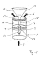
- FIG. 1 a gas inlet with float is shown in three-dimensional representation.
- a gas inlet 1 is designed, for example, in the form of a sleeve 3.
- the gas flows, as shown by arrows 5, from below into the sleeve 3, wherein the sleeve 3 is for this purpose, for example, connected to a gas-carrying pipe or the end of a gas-carrying pipe.
- the sleeve 3 is preferably aligned vertically, wherein the gas flows from below into the sleeve 3 and flows out of the sleeve 3 at the top.
- a guide ring 7 is received, wherein the guide ring 7 is fixed with webs 9 on the inner wall 11 of the sleeve 3.
- the guide ring 7 is fixed with webs 9 on the inner wall 11 of the sleeve 3.
- any other possible fastening, with which the guide ring 7 can be fixed in the sleeve 3, is conceivable.
- a float 13 is guided with a guide rod 15.
- the float 13 is designed in the form of a hollow cone 17 with a solid tip 19 in the embodiment shown here. Due to the massive tip 19, the center of gravity of the hollow cone 17 is displaced in the direction of the tip 19. A further displacement of the center of gravity results from the guide rod 15. This ensures that the center of gravity of the float 13 is lower than the force application point of the resistance force of the gas flow. Due to the low position of the center of gravity, the position of the float 13 stabilizes when it starts to tilt. In this way it can be avoided that the float 13 can tilt.
- a guide stop 21 is formed, for example in the form of a formed on the guide rod 15 ring. This can for example be screwed onto the guide rod 15.
- the guide stop 21 By the guide stop 21, the upward movement of the float 13 is limited at flowing gas upwards. As a result, as already described above, an up and down swing of the float can be prevented.
- the float 13 In operation, the float 13 is lifted by the gas flow 5 and thus releases the upper end of the sleeve 3.
- the gas can flow freely out of the sleeve.
- the float drops down and strikes the upper end of the sleeve 3.
- the sleeve 3 is closed, so that when used for gas supply in a fluidized bed or a moving bed is prevented that particles can get into the sleeve 3.
- FIG. 2 shows a sectional view of a gas distributor nozzle with float in the closed position and FIG. 3 in open position.
- the gas distributor nozzle 25 comprises a sleeve 3, the sleeve 3 in the embodiment shown here having a lower portion 27 with a smaller inner diameter and an upper portion 29 with a larger inner diameter.
- a stop 31 is formed, on which the float 13 with closed gas distributor 25 - as shown here - rests.
- the guide rod 15 of the float 13 is guided.
- the inner diameter of the upper portion 29 is greater than the maximum diameter of the float 13.
- a hood 33 with an inner ring 35 is screwed onto the sleeve 3.
- openings 37 are formed through which the gas can flow into a gap 39 between the hood 33 and the sleeve 3. From the gap 39, the gas flows through openings 41.
- FIG. 3 For example, the position of the float 13 is shown when gas flows through the gas distribution nozzle 25.
- the flowing gas of the float 13 is raised so far until the guide stop 21 abuts the guide rod 15 on the guide ring 7. Due to the upper boundary, a swinging of the float 13 is prevented and thereby pressure fluctuations in the gas inlet 1 can be reduced, so that the gas flow 5 remains uniform.
Landscapes
- Chemical & Material Sciences (AREA)
- Organic Chemistry (AREA)
- Chemical Kinetics & Catalysis (AREA)
- Engineering & Computer Science (AREA)
- Combustion & Propulsion (AREA)
- Devices And Processes Conducted In The Presence Of Fluids And Solid Particles (AREA)
Priority Applications (5)
| Application Number | Priority Date | Filing Date | Title |
|---|---|---|---|
| EP13195614.6A EP2881169A1 (fr) | 2013-12-04 | 2013-12-04 | Buse de distribution de gaz |
| EP14805930.6A EP3077097B1 (fr) | 2013-12-04 | 2014-12-03 | Buse de distribution de gaz et réacteur |
| US15/100,367 US9993792B2 (en) | 2013-12-04 | 2014-12-03 | Gas distribution nozzle |
| PCT/EP2014/076328 WO2015082506A1 (fr) | 2013-12-04 | 2014-12-03 | Buse de distribution de gaz |
| CN201480074836.4A CN105960278B (zh) | 2013-12-04 | 2014-12-03 | 气体分布器喷嘴 |
Applications Claiming Priority (1)
| Application Number | Priority Date | Filing Date | Title |
|---|---|---|---|
| EP13195614.6A EP2881169A1 (fr) | 2013-12-04 | 2013-12-04 | Buse de distribution de gaz |
Publications (1)
| Publication Number | Publication Date |
|---|---|
| EP2881169A1 true EP2881169A1 (fr) | 2015-06-10 |
Family
ID=49726554
Family Applications (2)
| Application Number | Title | Priority Date | Filing Date |
|---|---|---|---|
| EP13195614.6A Ceased EP2881169A1 (fr) | 2013-12-04 | 2013-12-04 | Buse de distribution de gaz |
| EP14805930.6A Active EP3077097B1 (fr) | 2013-12-04 | 2014-12-03 | Buse de distribution de gaz et réacteur |
Family Applications After (1)
| Application Number | Title | Priority Date | Filing Date |
|---|---|---|---|
| EP14805930.6A Active EP3077097B1 (fr) | 2013-12-04 | 2014-12-03 | Buse de distribution de gaz et réacteur |
Country Status (4)
| Country | Link |
|---|---|
| US (1) | US9993792B2 (fr) |
| EP (2) | EP2881169A1 (fr) |
| CN (1) | CN105960278B (fr) |
| WO (1) | WO2015082506A1 (fr) |
Cited By (1)
| Publication number | Priority date | Publication date | Assignee | Title |
|---|---|---|---|---|
| WO2017103023A1 (fr) * | 2015-12-17 | 2017-06-22 | Solvay Sa | Procédé d'extraction de gaz au moyen de particules adsorbantes, adsorbeur et système d'extraction de gaz |
Families Citing this family (5)
| Publication number | Priority date | Publication date | Assignee | Title |
|---|---|---|---|---|
| CN106268588B (zh) * | 2016-08-24 | 2017-12-26 | 西南化工研究设计院有限公司 | 一种高效气液反应釜及其在环氧乙烷和二氧化碳酯化反应中的应用 |
| CN112439363A (zh) * | 2019-09-05 | 2021-03-05 | 中石油吉林化工工程有限公司 | 丙烯氨分布器 |
| CN113019281B (zh) * | 2021-04-22 | 2022-12-16 | 沈阳美佳营养科技有限公司 | 一种抗菌肽饲料添加剂制备生产线 |
| CN115750854B (zh) * | 2021-09-03 | 2026-04-07 | 苏州纽威阀门股份有限公司 | 一种安全壳隔离止回阀 |
| CN114195251A (zh) * | 2021-11-29 | 2022-03-18 | 张化机(苏州)重装有限公司 | 一种蒸汽分布器 |
Citations (9)
| Publication number | Priority date | Publication date | Assignee | Title |
|---|---|---|---|---|
| GB668325A (en) * | 1949-07-08 | 1952-03-12 | Merevale Engineering Company L | Improvements relating to non-return valves |
| FR1233498A (fr) * | 1959-04-27 | 1960-10-12 | Gen Am Transport | Appareillage pour la fluidisation de matières solides |
| US3386182A (en) | 1965-09-18 | 1968-06-04 | Bayer Ag | Method of and apparatus for the mixing, drying or moistening by pneumatic means of material in powder form |
| US3921663A (en) | 1972-09-11 | 1975-11-25 | Ceskoslovenska Akademie Ved | Cap for inlet of fluid into a fluidized bed |
| US4387667A (en) | 1981-12-14 | 1983-06-14 | Combustion Engineering, Inc. | Fluidized bed distributor plate assembly |
| JPS63252540A (ja) * | 1987-04-09 | 1988-10-19 | Res Assoc Petroleum Alternat Dev<Rapad> | 三相流動反応装置 |
| DE4443292A1 (de) * | 1994-12-06 | 1996-06-13 | Metallgesellschaft Ag | Verteilereinrichtung für ein Fluid in einem Behälter |
| NL1004621C2 (nl) * | 1996-11-27 | 1998-05-28 | Ind Tech Res Inst | Vloeistofverdeler. |
| US5806206A (en) * | 1997-08-22 | 1998-09-15 | Osram Sylvania Inc. | Gas distributor for vertical gas/solid reactors |
Family Cites Families (3)
| Publication number | Priority date | Publication date | Assignee | Title |
|---|---|---|---|---|
| CH660561A5 (de) * | 1982-08-30 | 1987-05-15 | Escher Wyss Gmbh | Ringspaltduese und deren verwendung in einem fliessbetttrockner. |
| CN201361547Y (zh) * | 2008-12-25 | 2009-12-16 | 浙江富士特硅材料有限公司 | 三氯氢硅生产用流化床反应器及其气体分布器 |
| CN105722588A (zh) | 2013-11-21 | 2016-06-29 | 巴斯夫欧洲公司 | 用于实施吸热反应且在反应管中形成流化层的方法和装置 |
-
2013
- 2013-12-04 EP EP13195614.6A patent/EP2881169A1/fr not_active Ceased
-
2014
- 2014-12-03 CN CN201480074836.4A patent/CN105960278B/zh active Active
- 2014-12-03 EP EP14805930.6A patent/EP3077097B1/fr active Active
- 2014-12-03 WO PCT/EP2014/076328 patent/WO2015082506A1/fr not_active Ceased
- 2014-12-03 US US15/100,367 patent/US9993792B2/en active Active
Patent Citations (9)
| Publication number | Priority date | Publication date | Assignee | Title |
|---|---|---|---|---|
| GB668325A (en) * | 1949-07-08 | 1952-03-12 | Merevale Engineering Company L | Improvements relating to non-return valves |
| FR1233498A (fr) * | 1959-04-27 | 1960-10-12 | Gen Am Transport | Appareillage pour la fluidisation de matières solides |
| US3386182A (en) | 1965-09-18 | 1968-06-04 | Bayer Ag | Method of and apparatus for the mixing, drying or moistening by pneumatic means of material in powder form |
| US3921663A (en) | 1972-09-11 | 1975-11-25 | Ceskoslovenska Akademie Ved | Cap for inlet of fluid into a fluidized bed |
| US4387667A (en) | 1981-12-14 | 1983-06-14 | Combustion Engineering, Inc. | Fluidized bed distributor plate assembly |
| JPS63252540A (ja) * | 1987-04-09 | 1988-10-19 | Res Assoc Petroleum Alternat Dev<Rapad> | 三相流動反応装置 |
| DE4443292A1 (de) * | 1994-12-06 | 1996-06-13 | Metallgesellschaft Ag | Verteilereinrichtung für ein Fluid in einem Behälter |
| NL1004621C2 (nl) * | 1996-11-27 | 1998-05-28 | Ind Tech Res Inst | Vloeistofverdeler. |
| US5806206A (en) * | 1997-08-22 | 1998-09-15 | Osram Sylvania Inc. | Gas distributor for vertical gas/solid reactors |
Cited By (1)
| Publication number | Priority date | Publication date | Assignee | Title |
|---|---|---|---|---|
| WO2017103023A1 (fr) * | 2015-12-17 | 2017-06-22 | Solvay Sa | Procédé d'extraction de gaz au moyen de particules adsorbantes, adsorbeur et système d'extraction de gaz |
Also Published As
| Publication number | Publication date |
|---|---|
| US9993792B2 (en) | 2018-06-12 |
| CN105960278A (zh) | 2016-09-21 |
| EP3077097A1 (fr) | 2016-10-12 |
| CN105960278B (zh) | 2019-05-21 |
| EP3077097B1 (fr) | 2018-08-29 |
| WO2015082506A1 (fr) | 2015-06-11 |
| US20170165625A1 (en) | 2017-06-15 |
Similar Documents
| Publication | Publication Date | Title |
|---|---|---|
| EP3077097B1 (fr) | Buse de distribution de gaz et réacteur | |
| DE3630536C2 (fr) | ||
| DE2429291C2 (de) | Verfahren und Vorrichtung zur chemischen und/oder physikalischen Behandlung von Fluiden | |
| DE2626586C2 (de) | Gasverteilungsboden für ein Wirbelbett | |
| EP2435736B1 (fr) | Soupape de régulation, notamment soupape de regulation angulaire et soupape de regulation double, servant aussi de soupape a siege droit et oblique, pour des applications de regulation extremes | |
| WO2018166666A1 (fr) | Unité d'insertion sanitaire | |
| DE69818695T2 (de) | Vortex-ring-mischer mit gemässigtem verhaten der vortex-ringe | |
| EP3054060A1 (fr) | Élement de sortie sanitaire | |
| DE102007028438A1 (de) | Gasdüse und Reaktor hiermit | |
| EP1836356B1 (fr) | Regulateur du jet | |
| WO2014139618A1 (fr) | Régulateur de jet pourvu d'une surface d'impact dotée de parois annulaires | |
| EP1658891A1 (fr) | Réacteur à lit fluidisé avec un séparateur cyclonique | |
| DE68907595T2 (de) | Zerstäubungsdüsen. | |
| DE2611336A1 (de) | Ventil | |
| EP2159526A2 (fr) | Installation de traitement pour produits en vrac | |
| DE112016000931T5 (de) | Sprühdüse und Entlüfter | |
| DE102005006570A1 (de) | Verfahren und Vorrichtung zur Fluidisierung einer Wirbelschicht | |
| DE102012000536B3 (de) | Passiver Rückflussbegrenzer für ein Strömungsmedium | |
| EP2397655B1 (fr) | Vanne de régulation pour une turbine à vapeur | |
| EP3154673A1 (fr) | Réacteur à lit fluidisé présentant une direction horizontale | |
| EP3146117A1 (fr) | Régulateur de jet | |
| DE10227473B4 (de) | Primärluftdüse für einen Wirbelschichtreaktor | |
| EP4264097A1 (fr) | Piston de régulation pour réduire la pression fluidique dans une soupape de réglage | |
| EP1577002A1 (fr) | Réacteur à lit fluidisé avec une fente annulaire | |
| DE3102167A1 (de) | Vorrichtung zum aufteilen eines fluids oder fluidisierten hauptstroms zwischen mehreren nebenleitungen |
Legal Events
| Date | Code | Title | Description |
|---|---|---|---|
| PUAI | Public reference made under article 153(3) epc to a published international application that has entered the european phase |
Free format text: ORIGINAL CODE: 0009012 |
|
| 17P | Request for examination filed |
Effective date: 20131204 |
|
| AK | Designated contracting states |
Kind code of ref document: A1 Designated state(s): AL AT BE BG CH CY CZ DE DK EE ES FI FR GB GR HR HU IE IS IT LI LT LU LV MC MK MT NL NO PL PT RO RS SE SI SK SM TR |
|
| AX | Request for extension of the european patent |
Extension state: BA ME |
|
| STAA | Information on the status of an ep patent application or granted ep patent |
Free format text: STATUS: THE APPLICATION HAS BEEN REFUSED |
|
| 18R | Application refused |
Effective date: 20150627 |