EP0103792A2 - Dispositif pour commuter une connexion électrique en fonction du courant et/ou de la température - Google Patents
Dispositif pour commuter une connexion électrique en fonction du courant et/ou de la température Download PDFInfo
- Publication number
- EP0103792A2 EP0103792A2 EP83108625A EP83108625A EP0103792A2 EP 0103792 A2 EP0103792 A2 EP 0103792A2 EP 83108625 A EP83108625 A EP 83108625A EP 83108625 A EP83108625 A EP 83108625A EP 0103792 A2 EP0103792 A2 EP 0103792A2
- Authority
- EP
- European Patent Office
- Prior art keywords
- contact
- counter
- bimetallic
- tongue
- temperature
- Prior art date
- Legal status (The legal status is an assumption and is not a legal conclusion. Google has not performed a legal analysis and makes no representation as to the accuracy of the status listed.)
- Granted
Links
- 230000013011 mating Effects 0.000 claims description 39
- 210000002105 tongue Anatomy 0.000 claims description 38
- 238000013459 approach Methods 0.000 claims description 5
- 230000001419 dependent effect Effects 0.000 claims description 4
- 238000000576 coating method Methods 0.000 abstract description 4
- 230000000694 effects Effects 0.000 abstract description 4
- 238000013461 design Methods 0.000 abstract description 3
- 230000001681 protective effect Effects 0.000 abstract 1
- 238000001816 cooling Methods 0.000 description 6
- 238000004519 manufacturing process Methods 0.000 description 6
- 238000011109 contamination Methods 0.000 description 3
- 238000000034 method Methods 0.000 description 3
- 230000008569 process Effects 0.000 description 3
- 238000000926 separation method Methods 0.000 description 3
- 238000005452 bending Methods 0.000 description 2
- 230000008859 change Effects 0.000 description 2
- 238000011161 development Methods 0.000 description 2
- 230000018109 developmental process Effects 0.000 description 2
- 238000005516 engineering process Methods 0.000 description 2
- 229910052751 metal Inorganic materials 0.000 description 2
- 239000002184 metal Substances 0.000 description 2
- 230000003647 oxidation Effects 0.000 description 2
- 238000007254 oxidation reaction Methods 0.000 description 2
- 238000007789 sealing Methods 0.000 description 2
- 230000007704 transition Effects 0.000 description 2
- 239000000356 contaminant Substances 0.000 description 1
- 230000007797 corrosion Effects 0.000 description 1
- 238000005260 corrosion Methods 0.000 description 1
- 238000010438 heat treatment Methods 0.000 description 1
- 238000009434 installation Methods 0.000 description 1
- 239000011810 insulating material Substances 0.000 description 1
- 230000002427 irreversible effect Effects 0.000 description 1
- 230000007257 malfunction Effects 0.000 description 1
- 238000012986 modification Methods 0.000 description 1
- 230000004048 modification Effects 0.000 description 1
- 238000012544 monitoring process Methods 0.000 description 1
- TWNQGVIAIRXVLR-UHFFFAOYSA-N oxo(oxoalumanyloxy)alumane Chemical compound O=[Al]O[Al]=O TWNQGVIAIRXVLR-UHFFFAOYSA-N 0.000 description 1
- 239000003507 refrigerant Substances 0.000 description 1
- 238000005057 refrigeration Methods 0.000 description 1
- 230000000284 resting effect Effects 0.000 description 1
Images

Classifications
-
- H—ELECTRICITY
- H01—ELECTRIC ELEMENTS
- H01H—ELECTRIC SWITCHES; RELAYS; SELECTORS; EMERGENCY PROTECTIVE DEVICES
- H01H37/00—Thermally-actuated switches
- H01H37/02—Details
- H01H37/32—Thermally-sensitive members
- H01H37/52—Thermally-sensitive members actuated due to deflection of bimetallic element
- H01H37/54—Thermally-sensitive members actuated due to deflection of bimetallic element wherein the bimetallic element is inherently snap acting
- H01H37/5427—Thermally-sensitive members actuated due to deflection of bimetallic element wherein the bimetallic element is inherently snap acting encapsulated in sealed miniaturised housing
-
- H—ELECTRICITY
- H01—ELECTRIC ELEMENTS
- H01H—ELECTRIC SWITCHES; RELAYS; SELECTORS; EMERGENCY PROTECTIVE DEVICES
- H01H1/00—Contacts
- H01H1/12—Contacts characterised by the manner in which co-operating contacts engage
- H01H1/14—Contacts characterised by the manner in which co-operating contacts engage by abutting
- H01H1/18—Contacts characterised by the manner in which co-operating contacts engage by abutting with subsequent sliding
-
- H—ELECTRICITY
- H01—ELECTRIC ELEMENTS
- H01H—ELECTRIC SWITCHES; RELAYS; SELECTORS; EMERGENCY PROTECTIVE DEVICES
- H01H37/00—Thermally-actuated switches
- H01H37/02—Details
- H01H37/32—Thermally-sensitive members
- H01H37/52—Thermally-sensitive members actuated due to deflection of bimetallic element
- H01H37/54—Thermally-sensitive members actuated due to deflection of bimetallic element wherein the bimetallic element is inherently snap acting
- H01H2037/5463—Thermally-sensitive members actuated due to deflection of bimetallic element wherein the bimetallic element is inherently snap acting the bimetallic snap element forming part of switched circuit
-
- H—ELECTRICITY
- H01—ELECTRIC ELEMENTS
- H01H—ELECTRIC SWITCHES; RELAYS; SELECTORS; EMERGENCY PROTECTIVE DEVICES
- H01H37/00—Thermally-actuated switches
- H01H37/002—Thermally-actuated switches combined with protective means
-
- H—ELECTRICITY
- H01—ELECTRIC ELEMENTS
- H01H—ELECTRIC SWITCHES; RELAYS; SELECTORS; EMERGENCY PROTECTIVE DEVICES
- H01H37/00—Thermally-actuated switches
- H01H37/02—Details
- H01H37/32—Thermally-sensitive members
- H01H37/52—Thermally-sensitive members actuated due to deflection of bimetallic element
- H01H37/54—Thermally-sensitive members actuated due to deflection of bimetallic element wherein the bimetallic element is inherently snap acting
- H01H37/5418—Thermally-sensitive members actuated due to deflection of bimetallic element wherein the bimetallic element is inherently snap acting using cantilevered bimetallic snap elements
Definitions
- the invention relates to a device for temperature and / or current-dependent switching of an electrical connection, such as a temperature controller monitor or the like.
- a device for temperature and / or current-dependent switching of an electrical connection such as a temperature controller monitor or the like.
- a device for temperature and / or current-dependent switching of an electrical connection such as a temperature controller monitor or the like.
- a movable contact switchable when a predetermined temperature limit is exceeded by means of a bimetal element and a counter contact contact and counter contact with connection elements for Connection of supply lines are provided.
- the bimetal element carrying the movable contact urges further and further against contact and can be subject to irreversible changes, in particular deformations, which change pure switching temperatures beyond specified tolerances.
- the invention is therefore based on the object of providing such a device which is easy to manufacture in terms of production technology and in which a change in switching temperature is reliably avoided.
- the above-mentioned object is achieved in a device of the generic type in that the contact and counter-contact are connected to connecting elements which are kept at a distance by a common, insulating support part, and in that the counter-clock is elastically resiliently mounted on the support part.
- the device can be designed either as a make contact or as a break contact;
- the connection between the contact and the mating contact can therefore be broken if the temperature is too high than a predetermined switching temperature, for example in the case of a motor or the like for interrupting operation or as a controller in a heating device, while it is below the switching temperature Temperature closes;
- a predetermined switching temperature for example in the case of a motor or the like for interrupting operation or as a controller in a heating device, while it is below the switching temperature Temperature closes;
- the connection is opened at a temperature below the switching temperature and that the connection is closed at a temperature above the switching temperature, for example in the case of a cooling device, etc.
- the bimetal element can in principle be electrically conductive myself and, if appropriate, also as current-sensitive switch act, so switch its switching process not based on any ambient temperature, but on the basis of the heat generated directly in it by the current flow itself; in this case, of course, it opens when the heat is excessively generated, since this is only generated in the closed state.
- configurations are also possible in which the bimetal element is current-free and the current is conducted via other elements for movable contact, as is known in principle in a wide variety of ways.
- the support part is annular and on the one hand carries a substantially circular bimetal element on its circumference, which be Moving contact switches and on the other hand an elastic disc spring, which carries the mating contact, defines its circumference.
- the mating contact is arranged at one end of an elongated elastic tongue, a mating contact also being mounted on the supporting part; that the mounting of the counter-contact tongue takes place in that it is fixed to the supporting part with the section, and that the bimetallic element is also designed to be elongated, carries the movable contact at one end and is fixed to the supporting part with a non-contact area.
- the mating contact tongue is formed in one piece with its connecting element, and that the bimetallic element is connected to a conductive part, which on the one hand is frictionally attached to the supporting part and on the other hand forms a connecting element for the movable contact and / or that on Support part approaches are formed with undercuts, and that the connecting piece connected to the bimetallic element has edges which are bent out of its plane, and in this way the undercuts are introduced between the approaches and a central section of the supporting part, the edges of the approaches and the actual connecting piece at the central section being clamped of the supporting part abuts, and that edges corresponding to the edges are also formed on the counter-contact tongue in the region of a section, that the section is inserted with its edges in the undercuts corresponding to undercuts.
- the switch has considerable manufacturing advantages.
- the contact unit formed from the contact, the bimetal element, the connecting piece connected to this and the connecting piece formed integrally with this connecting piece on the one hand, and the counter-contact unit formed from the mating contact and the counter-contact tongue and the connecting element formed integrally with the connecting element, are only used to manufacture the switch clamped pressed into the prefabricated supporting part, the connecting elements being pushed through areas kept free between the respective two approaches.
- the switch manufactured in this way can then be used directly at its work station.
- the connection elements can be bent in a corresponding manner before attachment to the support part or afterwards, the latter is useful, for example, if an end plate is formed on the support part, around the edge of which the connection elements are then preferably guided around.
- the assembly described can be done fully automatically. Instead of being used at its operating point of the switch, which is complete in this respect, it can also be inserted into a housing, in which case a front end of the support part, which may be designed as an end plate, forms the end, while the other housing is designed in the form of a pocket.
- the connection elements are led out between the front plate and the housing and sealed at their lead-through points.
- the bimetallic element and / or the counter-contact tongue to shorten the free oscillating length of the Part profiles are formed, in the area of which the parts themselves are rigid, that is, not elastic or movable. If, for example, the mating contact is attached to a long tongue which is mounted on the supporting part at a greater distance from the mating contact, the free-swinging length or the lever arm can be shortened by such profiling. In the area of the profiling, the tongue is practically there and not elastic, it only remains elastic in the unprofiled, shorter area and can swing back into this area.
- the invention proposes to have contact and counter-contact switched by different bimetallic elements, one in particular being able to have current flowing through it and therefore forming a current-sensitive switch, while the other is electrically unloaded and only responds to the ambient temperature.
- the bimetallic element which is not affected by the current and is only temperature-sensitive, can act as a thermostat or controller, for example, to regulate the current flow to a cooling device or a heater, while the current-carrying bimetal element fulfills a monitoring function in the event of excessive current flow, for example a short circuit, and in this case causes a separation . It can be adjusted very well at what load, ie what current flow over which period of time the switching process should start. When coordinating the different switching conditions of the two bimetal elements, the most varied combinations can be selected.
- the device according to the invention for temperature-dependent switching of an electrical connection has a support part 1 for the essential switching elements in the exemplary embodiment shown.
- the device can be surrounded by a housing 2, as is the case in the illustrated embodiments; but this need not be so, the device could also be used in a recess in the device to be controlled or monitored or the like, a protruding end plate 3 at one end of the support part 1 completely closing the opening of such a recess.
- a switch according to the invention could also be used in the recess there.
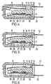
- the device according to the invention has a movable contact 6 on the one hand and a mating contact 7 assigned to it on the other hand.
- the contact 6 is formed at the front end of an elongated, tongue-shaped bimetal element 8, which is fastened with its rear end 9 to a connecting piece 11, for example welded to tongues formed thereon, which merges into a connecting element 12 projecting from the supporting part 1 via its end plate 3 .
- the contact unit formed by the parts 6, 8, 9, 11 could be fastened to the support part 1, which consists of insulating material, by screwing or riveting in the area of the connecting piece.
- the support part 1 points upwards and inwards from its central section 13 on its two edges projecting lugs 14, 14 ', which form groove-shaped undercuts 16, 16' towards the central part 13 ( Figure 3).
- edge regions 17, 17 'of the same are bent out of the plane of the actual connecting piece 11 somewhat more than this corresponds to the height of the undercuts 16, 16'.
- the unit 6, 8, 9, 11, 12 is with its connector.
- the mating contact 7 is formed at the front end of a mating contact tongue 18, which is formed in a transition section 19 in the manner corresponding to the connecting piece 11, described with reference to FIG. 3, and from which it integrally merges into an associated connecting element 21, and such forms a counter-contact unit 7, 18, 19, 21, which, as said, is also fixed to the support part 1 in the manner explained with reference to the contact unit 6, 8, 9, 11, 12.
- the mating contact tongue 18 consists of an inherently elastic metal part, such as an elastic sheet metal part. Since, as said, it is only fastened in the area of the transition piece 19, the counter-contact 7 can evade a pressure acting on it, in which the counter-contact tongue 18 bends elastically away from the supporting part 1.
- the mating contact tongue 18 can in a suitable manner be a profile 22, as is the case in the illustrated embodiment, this profiling 22 stiffening the mating contact tongue 18 over its length.
- FIG. 1 shows the preferred embodiment of the device in a contact interruption position, which generally corresponds to a high-temperature position, in which the temperature is therefore above a predetermined value and therefore a power interruption must take place.
- the bimetallic element 6 bends in the manner shown in FIG. 1 and lifts the contact 6 from the mating contact 7, so that the current is interrupted. If the temperature now drops below a predetermined value, the bimetallic disc 8 jumps over from its position shown in FIG. 1 and thus brings the contact 6 into contact with the mating contact 7.
- the bimetallic element 8 bends just so far that the Contact comes into contact with the counter contact 7, ot that the contact 6 exerts a greater force on the counter contact 7, so that the latter itself largely remains in its position shown in FIG. 1.
- the elastically bendable mating contact tongue can now be used due to the elastic mounting of the mating contact 7 18 recede and give way to the force of the Bielement 8 against. This avoids that at such low temperatures the internal stress of the bimetal element becomes extremely large on the one hand, but on the other hand it cannot bend further because its contact bears against a stationary mating contact, as a result of which the high voltages of the bimetal element at these low temperatures could lead to damage to the bimetal element itself, plastic changes and, in particular, considerable changes in the switching temperature.
- the tolerance limit of the switching temperature of the bimetal element 8 is always maintained under all conditions.
- the bimetal element 8 moves or pivots over its entire length from its end 9 attached to the connecting piece 11 to the contact 6.
- the force of the counter-contact tongue 18 can spring back only in its shorter area between the counter-contact 7 and the front end of the profiling 22.
- the free spring length of the bimetallic element 8 on the one hand and the counter-contact tongue 18 on the other hand is therefore different. This means that when the contact 6 comes into contact with the counter contact 7 and the counter contact 7 is pushed back by the contact 6, the contact 6 and the counter contact 7 do not always touch the same points, but rather they practically migrate and rub against each other.
- FIGS. 4 to 6 of the device according to the invention have two switching elements instead of one switching element, namely the bimetal element 8 of the embodiment of FIGS.
- a switching element can bring about temperature control by moving back and forth within certain temperature ranges, while the other switching element, such as the bimetallic element 8, merely monitors the temperature, i.e. ensures an interruption at excessively high temperatures.
- One switching element could also only respond to ambient temperatures, while the other switching element, such as the bimetallic element 8, responds to excessive current flow and causes an interruption of contact due to heat development in it caused by excessive current flow.
- FIGS. 4 to 6 is explained in detail below, the same reference numerals being used for the parts and elements already described with reference to FIGS. 1 to 3 and, insofar as is not absolutely necessary, no renewed explanation is carried out, but basically insofar reference is made to the explanation of the configuration of FIGS. 1 to 3.
- the supporting part 1 has on its side facing the counter-contact tongue 18 an annular recess 26 (which is also provided in the configuration of FIGS. 1 to 3, but has no special function there itself) ) with a central centering nose 27.
- a largely ring-shaped bimetal disc 28 is inserted into this recess between the central part 1 and counter-contact tongue 18, the bimetal disc 28 being centered by the centering lug 27 and held in place.
- the bimetallic disc 28 is inserted in such a way that it is at its low temperature position ( Figure 6) is unloaded and in particular the counter-contact tongue 18 can freely come to rest on the support part 1, while in its high temperature position ( Figures 5 and 6) with its inner circumference on the support part 1 and with its outer circumference on the counter-contact tongue 18 abuts and therefore pushes it away from the supporting part 1 1, so as to interrupt the electrical connection to the contact 6.
- the switching temperature of the bimetallic element 8 of the contact 6 is above the switching temperature of the bimetallic disc 28.
- FIG. 4 the position of the bimetallic element 8 and the bimetallic disc 28 is now shown at a temperature which is above both switching temperatures.
- the bimetallic element 8 lifts the contact 6 upwards and therefore initially causes an electrical separation.
- the bimetallic disc 28 pushes the mating contact tongue 18 and with it the mating contact 7 downward and likewise in turn causes an electrical separation of the contacts 6, 7.
- the ambient temperature drops to a value below the switching temperature of the bimetal element 8 but remains above the. Switching temperature of the bimetallic disc 28, the bimetallic element 8 snaps from the position in FIG. 4 to the position in FIG.
- the mating contact 7 can move freely downwards under the acting force of the contact 6, as has already been explained with reference to the configuration of FIGS. 1 to 3.
- the bimetallic element 8 does not have to switch under the effect of the ambient temperature, but can also shade itself due to the current flow and the temperature increase caused thereby.
- the bimetallic elements 8, 28 are arranged in such a way that they move the two contacts 6, 7 apart in their high-temperature positions, their switching temperatures must not be distributed in such a way that the switching temperature of the bimetallic element 8 is higher than that of the bimetallic disc 28. If the switching temperature the bimetallic disc 28 is higher than that of the bimetallic element 8 in the arrangement of the two elements shown, the bimetallic element 8 would still remain in its position corresponding to FIG. 4 at an ambient temperature between the two switching temperatures, while the bimetallic disc 28 and thus the mating contact Tongue 18 with its mating contact 7 would assume the position of FIG. 6, but the bimetallic element 8 would still interrupt the current flow.
- the two bimetallic elements 8, 28 do not have to be arranged in the manner shown that, in their high-temperature positions, they press the two contacts 6, 7 apart.
- the bimetallic disc 28 could be arranged in such a way that it corresponds to the figure 4 and 5 ent speaking position is the position below the switching temperature, i.e. the low temperature position and the position shown in FIG. 6 is the high temperature position, while the position of FIGS. 5 and 6 of the bimetal element 8 is the position for normal current flow and the position of FIG. 4 of the bimetal element 8 is the position with excessive current flow, for example a short circuit.
- the function would then be such that with normal current flow the bimetallic element 8 with the contact 6 is in the position of FIGS. 5 and 6 as the normal operating position. If the ambient temperatures are sufficiently low (it should be cooled) - the bimetallic disc is in the position of FIG. 5 and therefore cuts off the power supply to the cooling device. If the temperature now rises, the bimetallic disc 28 jumps to the position in FIG. 6 and therefore enables the circuit to be closed so that the optionally connected cooling device can work. Flows due to a malfunction or the like. an excessive current, the bimetallic element 8 can jump upward from the position of FIG. 6 due to the heat developing in it and detach the connection of the contact 6 to the mating contact 7, although cooling should actually be carried out from the ambient temperature.
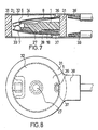
- FIGS. 7 and 8 show a further embodiment of the device according to the invention, which can be used particularly advantageously if the switching elements have to be arranged in a completely tight manner in a housing, as is important, for example, for use in refrigeration compressors, where hermetic sealing of the switching chamber is necessary , because the switch itself is flushed with refrigerant.
- the embodiment according to FIGS. 7 and 8 also initially generally has a supporting part 1.
- this supporting part is provided with an outer section designed as a ring 31.
- Metallic housing covers 32 and 33 are placed on both sides of the ring 31, which are firmly connected to the ring 31 and thus enclose a hermetically sealed chamber 34.
- the connection and sealing can take place in a wide variety of ways, for example the covers 32, 33 can be flanged at their edges and, if necessary, for this purpose.
- the ring 31 have corresponding outer grooves in which the flanged edges of the covers 32 and 33 engage.
- the ring 31 is metallized on its end faces, it could be designed, for example, as an insulating aluminum oxide body, and then the housing covers 32, 33 are soldered onto the ring, for example.
- the housing covers 32, 33 are punctiformly provided with notches 36, 37, on which the bimetallic element 8, which is largely also annular, and on the other hand the counter-contact tongue 18 are then fixed, for example soldered.
- the support member 1 carries the centering nose 27, which centers the centering of the further on the counter-contact tongue 18 and thus the counter-contact 7 acting bimetallic disc 28.
- Both housing covers 32, 33 are provided with connecting tongues 38, 39.
- the free length of the bimetal element 8 or the counter-contact tongue 18 also differed in this embodiment depending on the arrangement and design of the notches 36 and 37! I can be selected Except for the constructional differences shown and explained, the configuration according to FIGS. 7 and 8 functions and functions in the same way as the configurations explained above, in particular the configurations of FIGS. 4 to 6 provided with the second bimetallic disk 28, so that no need to go into this separately.
- the device according to the invention with its basic features enables further modifications and refinements.
- a current flow through the bimetallic element 8 itself could also be avoided and the bearing of the contact 6 could take place in a variety of other ways via movable cutting edge bearings or spring snap disks, which themselves conduct the current in the contacting device, while the bimetallic element itself does not correspond to the bimetallic disc 28 Current leads, but only causes the switching process.
- switching systems can also be used in the device according to the invention, as explained in various other applications and property rights of the inventor.
Landscapes
- Physics & Mathematics (AREA)
- Thermal Sciences (AREA)
- Thermally Actuated Switches (AREA)
- Emergency Protection Circuit Devices (AREA)
Priority Applications (1)
| Application Number | Priority Date | Filing Date | Title |
|---|---|---|---|
| AT83108625T ATE33909T1 (de) | 1982-09-16 | 1983-09-01 | Vorrichtung zum temperatur- und/oder stromabhaengigen schalten einer elektrischen verbindung. |
Applications Claiming Priority (2)
| Application Number | Priority Date | Filing Date | Title |
|---|---|---|---|
| DE19823234373 DE3234373A1 (de) | 1982-09-16 | 1982-09-16 | Vorrichtung zum temperatur- und/oder stromabhaengigen schalten einer elektrischen verbindung |
| DE3234373 | 1982-09-16 |
Publications (3)
| Publication Number | Publication Date |
|---|---|
| EP0103792A2 true EP0103792A2 (fr) | 1984-03-28 |
| EP0103792A3 EP0103792A3 (en) | 1987-01-07 |
| EP0103792B1 EP0103792B1 (fr) | 1988-04-27 |
Family
ID=6173393
Family Applications (1)
| Application Number | Title | Priority Date | Filing Date |
|---|---|---|---|
| EP83108625A Expired EP0103792B1 (fr) | 1982-09-16 | 1983-09-01 | Dispositif pour commuter une connexion électrique en fonction du courant et/ou de la température |
Country Status (5)
| Country | Link |
|---|---|
| US (1) | US4563667A (fr) |
| EP (1) | EP0103792B1 (fr) |
| JP (1) | JPS59132525A (fr) |
| AT (1) | ATE33909T1 (fr) |
| DE (2) | DE3234373A1 (fr) |
Cited By (2)
| Publication number | Priority date | Publication date | Assignee | Title |
|---|---|---|---|---|
| EP0187480A1 (fr) * | 1984-12-05 | 1986-07-16 | Elmwood Sensors Limited | Interrupteur sensible à la température |
| DE102007014237A1 (de) | 2007-03-16 | 2008-09-18 | Hofsaess, Marcel P. | Temperaturabhängiger Schalter und dafür vorgesehenes Schaltwerk |
Families Citing this family (20)
| Publication number | Priority date | Publication date | Assignee | Title |
|---|---|---|---|---|
| JPS63160636U (fr) * | 1987-04-09 | 1988-10-20 | ||
| DE3744238A1 (de) * | 1987-12-24 | 1989-07-06 | Inter Control Koehler Hermann | Temperatursicherung fuer elektrische geraete |
| JPH0731051A (ja) * | 1993-07-05 | 1995-01-31 | Texas Instr Japan Ltd | 過昇温防止機能付き過電流保護装置 |
| US5933068A (en) * | 1996-07-05 | 1999-08-03 | Dekel; Aram | Protective apparatus for an electrical installation having temperature-sensitive disconnection means |
| DE19636640C2 (de) * | 1996-09-10 | 1999-02-18 | Marcel Hofsaes | Schalter mit einem Sicherheitselement |
| DE19807288C2 (de) * | 1998-02-23 | 2001-09-20 | Marcel Hofsaes | Temperaturabhängiger Schalter |
| DE19847208C2 (de) * | 1998-10-13 | 2002-05-16 | Marcel Hofsaes | Schalter mit einem Isolierstoffträger |
| DE19847209C2 (de) * | 1998-10-13 | 2002-04-25 | Marcel Hofsaes | Schalter mit einem Isolierstoffträger |
| US6559752B1 (en) * | 1999-05-24 | 2003-05-06 | Frank J. Sienkiewicz | Creepless snap acting bimetallic switch having flexible contact members |
| JP3756700B2 (ja) * | 1999-07-22 | 2006-03-15 | ウチヤ・サーモスタット株式会社 | サーマルプロテクタ |
| US6498559B1 (en) | 2000-05-24 | 2002-12-24 | Christopher Cornell | Creepless snap acting bimetallic switch having step adjacent its bimetallic element |
| US7265652B2 (en) * | 2001-07-10 | 2007-09-04 | Yingco Electronic Inc. | Controllable electronic switch |
| US7324876B2 (en) * | 2001-07-10 | 2008-01-29 | Yingco Electronic Inc. | System for remotely controlling energy distribution at local sites |
| DE112008003632B4 (de) * | 2008-01-28 | 2023-04-06 | Uchiya Thermostat Co., Ltd. | Hitzeschutz |
| JP5174893B2 (ja) * | 2008-04-10 | 2013-04-03 | ウチヤ・サーモスタット株式会社 | 外部操作型サーマルプロテクタ |
| DE112012002848B4 (de) * | 2011-07-04 | 2017-08-03 | Uchiya Thermostat Co., Ltd. | Temperaturschalter |
| US10551105B2 (en) * | 2015-07-31 | 2020-02-04 | Trane International Inc. | Multi-stage control for electromechanical heating, ventilation, and air conditioning (HVAC) unit |
| CN112805799B (zh) * | 2018-10-18 | 2025-03-07 | 打矢恒温器株式会社 | 电气元件的连接方法 |
| JP7397815B2 (ja) * | 2021-01-07 | 2023-12-13 | ボーンズ株式会社 | 熱応動スイッチ素子及び電気回路 |
| DE102023127597B3 (de) * | 2023-10-10 | 2025-02-13 | Marcel P. HOFSAESS | Temperaturabhängiger Schalter |
Citations (1)
| Publication number | Priority date | Publication date | Assignee | Title |
|---|---|---|---|---|
| DE2916639A1 (de) | 1979-04-25 | 1980-10-30 | Hofsass P | Spulenkoerper mit waermeschutzschalter |
Family Cites Families (12)
| Publication number | Priority date | Publication date | Assignee | Title |
|---|---|---|---|---|
| US2698368A (en) * | 1951-06-08 | 1954-12-28 | Dictograph Products Co Inc | Fire alarm |
| US2724753A (en) * | 1952-12-17 | 1955-11-22 | Gen Electric | Bimetal thermostatic switch |
| US3033960A (en) * | 1959-05-11 | 1962-05-08 | West Bend Co | Thermostatic switch |
| US3067306A (en) * | 1960-11-10 | 1962-12-04 | Texas Instruments Inc | Thermostatic switch |
| US3278705A (en) * | 1964-03-26 | 1966-10-11 | Sylvania Electric Prod | Thermostatic switch |
| JPS51159877U (fr) * | 1975-06-13 | 1976-12-20 | ||
| JPS5630100Y2 (fr) * | 1975-09-16 | 1981-07-17 | ||
| FR2455348B1 (fr) * | 1979-04-25 | 1985-10-18 | Hofsass P | Corps de bobine electrique a commutateur de protection contre la chaleur |
| US4262273A (en) * | 1979-11-29 | 1981-04-14 | Emerson Electric Co. | Thermostatic electrical switch |
| JPS5761232A (en) * | 1980-09-30 | 1982-04-13 | Matsushita Electric Works Ltd | Overcurrent protecting device |
| DE3104828A1 (de) * | 1981-02-11 | 1982-09-09 | Limitor AG, 8022 Zürich | "bimetalltemperaturschalter" |
| US4445105A (en) * | 1982-06-28 | 1984-04-24 | Portage Electric Products, Inc. | Thermostat |
-
1982
- 1982-09-16 DE DE19823234373 patent/DE3234373A1/de not_active Withdrawn
-
1983
- 1983-09-01 AT AT83108625T patent/ATE33909T1/de not_active IP Right Cessation
- 1983-09-01 EP EP83108625A patent/EP0103792B1/fr not_active Expired
- 1983-09-01 DE DE8383108625T patent/DE3376460D1/de not_active Expired
- 1983-09-09 US US06/530,700 patent/US4563667A/en not_active Expired - Lifetime
- 1983-09-16 JP JP58169520A patent/JPS59132525A/ja active Granted
Patent Citations (1)
| Publication number | Priority date | Publication date | Assignee | Title |
|---|---|---|---|---|
| DE2916639A1 (de) | 1979-04-25 | 1980-10-30 | Hofsass P | Spulenkoerper mit waermeschutzschalter |
Cited By (2)
| Publication number | Priority date | Publication date | Assignee | Title |
|---|---|---|---|---|
| EP0187480A1 (fr) * | 1984-12-05 | 1986-07-16 | Elmwood Sensors Limited | Interrupteur sensible à la température |
| DE102007014237A1 (de) | 2007-03-16 | 2008-09-18 | Hofsaess, Marcel P. | Temperaturabhängiger Schalter und dafür vorgesehenes Schaltwerk |
Also Published As
| Publication number | Publication date |
|---|---|
| JPS59132525A (ja) | 1984-07-30 |
| JPH0432489B2 (fr) | 1992-05-29 |
| EP0103792B1 (fr) | 1988-04-27 |
| DE3234373A1 (de) | 1984-05-10 |
| DE3376460D1 (en) | 1988-06-01 |
| ATE33909T1 (de) | 1988-05-15 |
| US4563667A (en) | 1986-01-07 |
| EP0103792A3 (en) | 1987-01-07 |
Similar Documents
| Publication | Publication Date | Title |
|---|---|---|
| EP0103792B1 (fr) | Dispositif pour commuter une connexion électrique en fonction du courant et/ou de la température | |
| DE3688800T2 (de) | Schutzsysteme für einen Kältemaschinenkompressormotor. | |
| DE69503743T2 (de) | Schutzvorrichtung gegen transiente Überspannungen mit Varistoren und thermischen Auslösern | |
| EP0342441B1 (fr) | Dispositif de commutation sensible à la température | |
| DE60113755T2 (de) | Elektrisches Schaltgerät mit einer Vakuumröhre und eine flexible elektrische Verbindung | |
| EP0887826B1 (fr) | Interrupteur à commande thermique avec pont de contact | |
| DE3122899C2 (de) | Temperaturschalter | |
| EP0284916B1 (fr) | Thermostat avec un boîtier | |
| DE3539559C2 (fr) | ||
| EP2874171B1 (fr) | Mécanisme de commutation variable avec la température | |
| EP3796359A1 (fr) | Commutateur dépendant de la température | |
| EP0951040B2 (fr) | Interrupteur à commande thermique | |
| EP0994497B1 (fr) | Interrupteur avec support isolant | |
| DE4329699C2 (de) | Fassung für elektrisches Bauteil | |
| DE3629650C2 (fr) | ||
| EP0453596A1 (fr) | Commutateur à température | |
| DE69512775T2 (de) | Zigarettenanzünderkörper insbesondere für kraftfahrzeuge | |
| EP0584587B1 (fr) | Interrupteur à fusible avec coupure de la tension aux deux cÔtés | |
| EP1389341B1 (fr) | Auxiliaire de serrage | |
| DE2916639C2 (de) | Spulenkörper mit einem Wärmeschutzschalter | |
| EP0860846A2 (fr) | Régulateur électrique de puissance, en particulier pour appareil à chauffage électrique | |
| EP0238960B1 (fr) | Appareil électrique d'installation | |
| DE102023102302B3 (de) | Temperaturabhängiger Schalter | |
| DE4400772C2 (de) | Elektrisches Schaltgerät | |
| DE2511214A1 (de) | Temperatur-sicherheitseinrichtung fuer elektrische geraete, insbesondere haushaltgeraete |
Legal Events
| Date | Code | Title | Description |
|---|---|---|---|
| PUAI | Public reference made under article 153(3) epc to a published international application that has entered the european phase |
Free format text: ORIGINAL CODE: 0009012 |
|
| AK | Designated contracting states |
Designated state(s): AT DE FR GB IT NL |
|
| PUAL | Search report despatched |
Free format text: ORIGINAL CODE: 0009013 |
|
| AK | Designated contracting states |
Kind code of ref document: A3 Designated state(s): AT DE FR GB IT NL |
|
| 17P | Request for examination filed |
Effective date: 19870130 |
|
| 17Q | First examination report despatched |
Effective date: 19870930 |
|
| GRAA | (expected) grant |
Free format text: ORIGINAL CODE: 0009210 |
|
| AK | Designated contracting states |
Kind code of ref document: B1 Designated state(s): AT DE FR GB IT NL |
|
| REF | Corresponds to: |
Ref document number: 33909 Country of ref document: AT Date of ref document: 19880515 Kind code of ref document: T |
|
| REF | Corresponds to: |
Ref document number: 3376460 Country of ref document: DE Date of ref document: 19880601 |
|
| ET | Fr: translation filed | ||
| ITF | It: translation for a ep patent filed | ||
| GBT | Gb: translation of ep patent filed (gb section 77(6)(a)/1977) | ||
| PLBE | No opposition filed within time limit |
Free format text: ORIGINAL CODE: 0009261 |
|
| STAA | Information on the status of an ep patent application or granted ep patent |
Free format text: STATUS: NO OPPOSITION FILED WITHIN TIME LIMIT |
|
| 26N | No opposition filed | ||
| ITTA | It: last paid annual fee | ||
| REG | Reference to a national code |
Ref country code: GB Ref legal event code: IF02 |
|
| PGFP | Annual fee paid to national office [announced via postgrant information from national office to epo] |
Ref country code: NL Payment date: 20020827 Year of fee payment: 20 Ref country code: AT Payment date: 20020827 Year of fee payment: 20 |
|
| PGFP | Annual fee paid to national office [announced via postgrant information from national office to epo] |
Ref country code: GB Payment date: 20020904 Year of fee payment: 20 |
|
| PGFP | Annual fee paid to national office [announced via postgrant information from national office to epo] |
Ref country code: FR Payment date: 20020909 Year of fee payment: 20 |
|
| PGFP | Annual fee paid to national office [announced via postgrant information from national office to epo] |
Ref country code: DE Payment date: 20021102 Year of fee payment: 20 |
|
| PG25 | Lapsed in a contracting state [announced via postgrant information from national office to epo] |
Ref country code: GB Free format text: LAPSE BECAUSE OF EXPIRATION OF PROTECTION Effective date: 20030831 |
|
| PG25 | Lapsed in a contracting state [announced via postgrant information from national office to epo] |
Ref country code: NL Free format text: LAPSE BECAUSE OF EXPIRATION OF PROTECTION Effective date: 20030901 Ref country code: AT Free format text: LAPSE BECAUSE OF EXPIRATION OF PROTECTION Effective date: 20030901 |
|
| REG | Reference to a national code |
Ref country code: GB Ref legal event code: PE20 |
|
| NLV7 | Nl: ceased due to reaching the maximum lifetime of a patent |
Effective date: 20030901 |