EP0103848A2 - Machine pour le finissage vibratoire de pièces - Google Patents
Machine pour le finissage vibratoire de pièces Download PDFInfo
- Publication number
- EP0103848A2 EP0103848A2 EP83109079A EP83109079A EP0103848A2 EP 0103848 A2 EP0103848 A2 EP 0103848A2 EP 83109079 A EP83109079 A EP 83109079A EP 83109079 A EP83109079 A EP 83109079A EP 0103848 A2 EP0103848 A2 EP 0103848A2
- Authority
- EP
- European Patent Office
- Prior art keywords
- drum
- workpieces
- machine according
- grinding machine
- grinding
- Prior art date
- Legal status (The legal status is an assumption and is not a legal conclusion. Google has not performed a legal analysis and makes no representation as to the accuracy of the status listed.)
- Granted
Links
Images

Classifications
-
- B—PERFORMING OPERATIONS; TRANSPORTING
- B24—GRINDING; POLISHING
- B24B—MACHINES, DEVICES, OR PROCESSES FOR GRINDING OR POLISHING; DRESSING OR CONDITIONING OF ABRADING SURFACES; FEEDING OF GRINDING, POLISHING, OR LAPPING AGENTS
- B24B31/00—Machines or devices designed for polishing or abrading surfaces on work by means of tumbling apparatus or other apparatus in which the work and/or the abrasive material is loose; Accessories therefor
- B24B31/06—Machines or devices designed for polishing or abrading surfaces on work by means of tumbling apparatus or other apparatus in which the work and/or the abrasive material is loose; Accessories therefor involving oscillating or vibrating containers
- B24B31/062—Machines or devices designed for polishing or abrading surfaces on work by means of tumbling apparatus or other apparatus in which the work and/or the abrasive material is loose; Accessories therefor involving oscillating or vibrating containers the workpieces travelling through the containers
Definitions
- the invention relates to a method for vibratory grinding of workpieces by means of grinding wheels or the like. under the influence of acceleration forces as well as a machine for performing this method.
- the invention has for its object the workpieces to be machined by means of grinding wheels by vibratory grinding to treat a new method in order to obtain workpieces machined better and for a short period of time, even those made of a very hard material, which previously could not be machined at all or could only be machined under the most difficult conditions with a time-consuming treatment.
- the surface grinding method for machining workpieces by means of grinding wheels or the like. to be designed in such a way that a homogeneous, essentially horizontal stream consisting of workpieces and grinding wheels is circularly limited in its lateral extent and is moved overall about a substantially horizontal axis.
- this method it is essential that the stream of workpieces and grinding wheels is summarized compactly and is circular in cross section and is moved in this form and in its entirety about an essentially horizontal axis. The latter means that the axis of the material flow on a circle or the like. -track moves. If these conditions are observed, an increase in performance which was not considered possible can be achieved, even with regard to workpieces consisting of materials which are difficult to machine.
- the slide grinding machine which can be used in particular for this method, is designed such that it has a substantially horizontally arranged drum which receives the flow of workpieces and grinding bodies and is completely filled by it, and is essentially rotationally stable in space with a circular cross section, which is arranged on a circular or. the like -Track is movable, the angular velocity of the drum wall about the axis of the drum is substantially "zero", and which at one end with an inlet opening and at the other end with one visually their cross-sectional area is provided adjustable outlet opening.
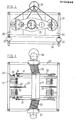
- the machine frame 12 containing the drum 11 is by means of air pressure spring elements th 13 stored on a base frame 14.
- the drum 11 is connected at its front and rear ends to the two rockers 15, 4h the ends of which are arranged the bearings 16, into which the crank pins 17 of the crank disks 18 engage.
- the crank disks 18 sit on the ends of the drive shafts 19, which are mounted on the transverse wall parts 20 of the machine frame 12.
- the counterweights 21 are attached to the shafts 19.
- the shafts 19 are driven via the toothed wheels 22 by means of the chain drives 23, which are driven in the same direction by the drive motor 24.
- the two ends of the drum 11 are each connected to a flexible, reinforced hose piece 25, the free ends of which are fastened in the machine frame 12.
- the inlet-side hose section 25 is connected to an inlet funnel 26.
- the outlet-side hose section 25 is connected to a shut-off element 27, which opens the outlet opening in the desired size.
- the drum is set in rotary motion by the crank drives 17 to 19 by means of the rockers 15, in which the axis 28 of the drum 11 rotates about the imaginary axis 29.
- the mixture of workpieces and grinding wheels is fed through the inlet funnel 26 and the inlet-side hose section 25.
- the shut-off member 27 at the outlet end of the hose section 25 the filling quantity of the drum is controlled in such a way that it is constantly filled during operation.
- the quantity of mixture of workpieces and grinding media that is running out is continuously increased on the inlet side, so that the drum always remains completely full.
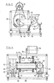
- the drum 11 ' is mounted eccentrically in the circular disks 31, which in turn are rotatably mounted in the transverse walls 32 of the machine frame 33.
- the two circular disks 31 are connected to one another by means of a cylinder 34 in order to ensure synchronization.
- the cylinder 34 is set in rotation by the drive motor 36 by means of a chain or belt drive 35.
- a lever arm 37 is arranged on the drum 11', the lower end of which is connected via a joint 38 by the handlebar 40 articulated on the base frame 39 is held.
- the inlet-side end of the drum 11 ' is connected to an inlet pipe 42 which is supported such that it has the required flexibility when rotating the drum.
- Both the inlet pipe 42 and the outlet pipe 43 are movably supported by means of the linkage 44 and their height or inclination can be adjusted by means of a lifting mechanism 45 in order to increase the filling quantity in the drum 11 'and to be able to regulate the throughput.
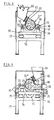
- the machine according to FIGS. 3 and 4 is configured similarly to that according to FIGS. 1 and 2; it is also operated in the same way.
- the machine according to FIG. 5 represents a variant, which works on the same principle as the machine according to FIGS. 1 and 2.
- a frame 52 is mounted on a base frame 51 by means of the compressed air spring elements 53 and supports the bearing blocks 54 for the shafts 56 driven by a drive motor 55.
- the eccentrics 57 are fastened on the shaft 56, which are rotatably mounted in the eccentric bearings 58 on the claws 59 "carrying the drum 11".
- the operation of this machine is the same as that of the machine described above If smaller, the inlet and outlet of the drum 11 "can be made simpler.
- the inlet funnel 60 is connected via a flexible hose or pipe piece 61 to the inlet nozzle 62 inserted tangentially on the top of the drum 11".
- the outlet nozzle provided with a gate valve is the same as in the machine variant according to FIG. 6.
- the inlet 78 for the workpiece-abrasive mixture is designed in the same way as in the machine according to FIG. 5.
- the outlet nozzle 79 is attached tangentially in the lower region of the drum 11 ′′ and is provided with a gate valve 80 which passes through a drive cylinder 81 is movable in order to be able to set the outlet opening 82 to a specific value in the desired manner.
- the slide grinding machines designed according to the invention make it possible to achieve extraordinary increases in performance compared to the known ones, since, as practice has shown, the acceleration values can be increased enormously. This is only possible if the mixture of workpiece and grinding media in the working drum completely fills it, since the acceleration forces can act continuously on the mixture via the drum walls. It has been shown that, in contrast to all other previously known machines, in these machines the workpieces in the mixture practically do not shift and do not bump into one another and damage one another, as can be observed in particular in the treatment of workpieces in open vibrating troughs.
- the main advantage of the surface grinding machines designed according to the invention lies in the enormous increase in performance. This means that workpieces which have hitherto been treated in the usual way require a treatment time which is a fraction of the previous one, and moreover the quality of the surface treatment is better.
Landscapes
- Engineering & Computer Science (AREA)
- Mechanical Engineering (AREA)
- Finish Polishing, Edge Sharpening, And Grinding By Specific Grinding Devices (AREA)
Applications Claiming Priority (2)
| Application Number | Priority Date | Filing Date | Title |
|---|---|---|---|
| DE19823234819 DE3234819A1 (de) | 1982-09-20 | 1982-09-20 | Verfahren und maschine zum gleitschleifen von werkstuecken |
| DE3234819 | 1982-09-20 |
Publications (3)
| Publication Number | Publication Date |
|---|---|
| EP0103848A2 true EP0103848A2 (fr) | 1984-03-28 |
| EP0103848A3 EP0103848A3 (en) | 1984-12-05 |
| EP0103848B1 EP0103848B1 (fr) | 1986-03-05 |
Family
ID=6173688
Family Applications (1)
| Application Number | Title | Priority Date | Filing Date |
|---|---|---|---|
| EP83109079A Expired EP0103848B1 (fr) | 1982-09-20 | 1983-09-14 | Machine pour le finissage vibratoire de pièces |
Country Status (3)
| Country | Link |
|---|---|
| US (1) | US4559742A (fr) |
| EP (1) | EP0103848B1 (fr) |
| DE (2) | DE3234819A1 (fr) |
Cited By (1)
| Publication number | Priority date | Publication date | Assignee | Title |
|---|---|---|---|---|
| WO2012022510A1 (fr) | 2010-08-19 | 2012-02-23 | Voestalpine Stahl Gmbh | Procédé pour conditionner la surface d'éléments en tôle d'acier trempés protégés contre la corrosion |
Families Citing this family (1)
| Publication number | Priority date | Publication date | Assignee | Title |
|---|---|---|---|---|
| CN114227518B (zh) * | 2021-12-31 | 2023-04-07 | 无锡市夸克微智造科技有限责任公司 | 一种柔性人工晶状体抛光机及柔性抛光方法 |
Family Cites Families (14)
| Publication number | Priority date | Publication date | Assignee | Title |
|---|---|---|---|---|
| DE686627C (de) * | 1938-03-12 | 1940-01-13 | Westfalia Dinnendahl Groeppel | Zerkleinerungsvorrichtung |
| DE1080894B (de) * | 1958-12-05 | 1960-04-28 | Walther Technik Carl Kurt Walt | Einrichtung zum Oberflaechenbearbeiten von Werkstuecken in Behaeltern |
| US3248826A (en) * | 1963-04-22 | 1966-05-03 | Wheelabrator Corp | Method for the finishing of parts |
| US3295768A (en) * | 1964-02-07 | 1967-01-03 | Us Stoneware Inc | Method of vibratory-milling |
| US3318051A (en) * | 1964-04-03 | 1967-05-09 | John F Rampe | Finishing apparatus |
| US3408774A (en) * | 1965-04-05 | 1968-11-05 | Pangborn Corp | Vibratory finishing apparatus |
| US3449869A (en) * | 1966-03-16 | 1969-06-17 | John F Rampe | Vibratory finishing machine |
| US3496677A (en) * | 1967-09-08 | 1970-02-24 | Albert G Bodine | Sonic polishing method and apparatus |
| US3552068A (en) * | 1968-09-09 | 1971-01-05 | Wheelabrator Corp | Vibrator construction for the surface treatment of articles |
| US3694968A (en) * | 1970-01-02 | 1972-10-03 | Vibrodyne Inc | Vibratory apparatus |
| US3685213A (en) * | 1970-02-05 | 1972-08-22 | Rampe Research | Orbital finishing system |
| US3959932A (en) * | 1972-07-11 | 1976-06-01 | Rampe Research | Finishing system with cyclically operable closure control |
| DE7626942U1 (de) * | 1976-08-27 | 1977-02-03 | Heiberger, Ernst, 7321 Reichenbach | Vibrations-schleif- und poliermaschine |
| SU667386A2 (ru) * | 1978-03-06 | 1979-06-15 | Львовский Лесотехнический Институт | Вибрационна машина |
-
1982
- 1982-09-20 DE DE19823234819 patent/DE3234819A1/de not_active Withdrawn
-
1983
- 1983-09-14 EP EP83109079A patent/EP0103848B1/fr not_active Expired
- 1983-09-14 DE DE8383109079T patent/DE3362445D1/de not_active Expired
- 1983-09-19 US US06/533,303 patent/US4559742A/en not_active Expired - Fee Related
Cited By (2)
| Publication number | Priority date | Publication date | Assignee | Title |
|---|---|---|---|---|
| WO2012022510A1 (fr) | 2010-08-19 | 2012-02-23 | Voestalpine Stahl Gmbh | Procédé pour conditionner la surface d'éléments en tôle d'acier trempés protégés contre la corrosion |
| DE102010037077A1 (de) | 2010-08-19 | 2012-02-23 | Voestalpine Stahl Gmbh | Verfahren zum Konditionieren der Oberfläche gehärteter korrosionsgeschützter Bauteile aus Stahlblech |
Also Published As
| Publication number | Publication date |
|---|---|
| US4559742A (en) | 1985-12-24 |
| DE3234819A1 (de) | 1984-03-22 |
| EP0103848B1 (fr) | 1986-03-05 |
| EP0103848A3 (en) | 1984-12-05 |
| DE3362445D1 (en) | 1986-04-10 |
Similar Documents
| Publication | Publication Date | Title |
|---|---|---|
| DE2901284C2 (de) | Bodenverdichtungsgerät mit Bodenplatte und Unwucht-Schwingungserzeuger | |
| DE1817452B2 (de) | Vibrationsschleifmaschine | |
| DE1652173A1 (de) | Vibrations-Schleifmuehle | |
| DE3790077C2 (fr) | ||
| DE1047993B (de) | Federnd gelagerte Einrichtung zum Putzen von Werkstuecken, insbesondere Rohgussstuecken | |
| DE2457828A1 (de) | Vorrichtung zur ausgabe von feinkoernigem material, insbesondere als verteilungsvorrichtung fuer sand und/oder salz | |
| CH467651A (de) | Vibrator zum Entgraten, Glätten, Polieren und Mischen | |
| DE102008000651B3 (de) | Verfahren zum Schleifen von Betonstein und Maschine zum Schleifen von Betonstein | |
| EP0103848A2 (fr) | Machine pour le finissage vibratoire de pièces | |
| DE3308810A1 (de) | Setzmaschine zur aufbereitung von kohle | |
| DE587121C (de) | Kollergangartige Misch- und Knetmaschine mit umlaufender Mahlbahn | |
| AT386767B (de) | Ballistischer sichter | |
| DE2212251C3 (de) | Vorrichtung zum Zerkleinern von in Rohkies enthaltenen, klumpenförmigen Fremdstoffen | |
| DE1841635U (de) | Vibrationsvorrichtung. | |
| DE1272767B (de) | Maschine zum Schleifen, Polieren, Entgraten, Putzen von Werkstuecken in Schwingtroegen | |
| DE400247C (de) | Vibrator fuer Siebe u. dgl. | |
| DE619662C (de) | Vorrichtung zum Mahlen von Trockensubstanzen, Pasten u. dgl. mittels Quarzsandes oder aehnlicher feinkoerniger Mahlkoerper | |
| DE484111C (de) | Langsiebmaschine zur Entwaesserung von Papier- oder Asbeststoff mit gleichzeitiger wagerechter und senkrechter Schuettelung des Siebes | |
| DE841066C (de) | Vibriereinrichtung | |
| DE653173C (de) | Mahlgang | |
| DE873645C (de) | Verfahren und Vorrichtung zur Sichtung von Schuettgut | |
| DE398057C (de) | Schuettelsieb | |
| AT106045B (de) | Auslesemaschine. | |
| DE1258298B (de) | Kontinuierlich arbeitende Maschine zur Oberflaechenbearbeitung von Werkstuecken durch Vibration | |
| DE2221816C3 (de) | Zwangsmischer, insbesondere für Beton |
Legal Events
| Date | Code | Title | Description |
|---|---|---|---|
| PUAI | Public reference made under article 153(3) epc to a published international application that has entered the european phase |
Free format text: ORIGINAL CODE: 0009012 |
|
| AK | Designated contracting states |
Designated state(s): CH DE FR GB IT LI |
|
| PUAL | Search report despatched |
Free format text: ORIGINAL CODE: 0009013 |
|
| AK | Designated contracting states |
Designated state(s): CH DE FR GB IT LI |
|
| 17P | Request for examination filed |
Effective date: 19841228 |
|
| ITF | It: translation for a ep patent filed | ||
| GRAA | (expected) grant |
Free format text: ORIGINAL CODE: 0009210 |
|
| AK | Designated contracting states |
Kind code of ref document: B1 Designated state(s): CH DE FR GB IT LI |
|
| REF | Corresponds to: |
Ref document number: 3362445 Country of ref document: DE Date of ref document: 19860410 |
|
| ET | Fr: translation filed | ||
| PLBE | No opposition filed within time limit |
Free format text: ORIGINAL CODE: 0009261 |
|
| STAA | Information on the status of an ep patent application or granted ep patent |
Free format text: STATUS: NO OPPOSITION FILED WITHIN TIME LIMIT |
|
| 26N | No opposition filed | ||
| ITTA | It: last paid annual fee | ||
| PGFP | Annual fee paid to national office [announced via postgrant information from national office to epo] |
Ref country code: GB Payment date: 19910805 Year of fee payment: 9 |
|
| PGFP | Annual fee paid to national office [announced via postgrant information from national office to epo] |
Ref country code: FR Payment date: 19910808 Year of fee payment: 9 |
|
| PGFP | Annual fee paid to national office [announced via postgrant information from national office to epo] |
Ref country code: CH Payment date: 19910813 Year of fee payment: 9 |
|
| PGFP | Annual fee paid to national office [announced via postgrant information from national office to epo] |
Ref country code: DE Payment date: 19911128 Year of fee payment: 9 |
|
| PG25 | Lapsed in a contracting state [announced via postgrant information from national office to epo] |
Ref country code: GB Effective date: 19920914 |
|
| PG25 | Lapsed in a contracting state [announced via postgrant information from national office to epo] |
Ref country code: LI Effective date: 19920930 Ref country code: CH Effective date: 19920930 |
|
| GBPC | Gb: european patent ceased through non-payment of renewal fee |
Effective date: 19920914 |
|
| PG25 | Lapsed in a contracting state [announced via postgrant information from national office to epo] |
Ref country code: FR Effective date: 19930528 |
|
| REG | Reference to a national code |
Ref country code: CH Ref legal event code: PL |
|
| PG25 | Lapsed in a contracting state [announced via postgrant information from national office to epo] |
Ref country code: DE Effective date: 19930602 |
|
| REG | Reference to a national code |
Ref country code: FR Ref legal event code: ST |