EP0103963A2 - Apparat zum miteinander Verseilen von wenigstens zwei Drähten - Google Patents
Apparat zum miteinander Verseilen von wenigstens zwei Drähten Download PDFInfo
- Publication number
- EP0103963A2 EP0103963A2 EP83304424A EP83304424A EP0103963A2 EP 0103963 A2 EP0103963 A2 EP 0103963A2 EP 83304424 A EP83304424 A EP 83304424A EP 83304424 A EP83304424 A EP 83304424A EP 0103963 A2 EP0103963 A2 EP 0103963A2
- Authority
- EP
- European Patent Office
- Prior art keywords
- twisting
- stranding
- wires
- tube
- station
- Prior art date
- Legal status (The legal status is an assumption and is not a legal conclusion. Google has not performed a legal analysis and makes no representation as to the accuracy of the status listed.)
- Granted
Links
Images
Classifications
-
- H—ELECTRICITY
- H01—ELECTRIC ELEMENTS
- H01B—CABLES; CONDUCTORS; INSULATORS; SELECTION OF MATERIALS FOR THEIR CONDUCTIVE, INSULATING OR DIELECTRIC PROPERTIES
- H01B13/00—Apparatus or processes specially adapted for manufacturing conductors or cables
- H01B13/02—Stranding-up
- H01B13/0235—Stranding-up by a twisting device situated between a pay-off device and a take-up device
Definitions
- This invention relates to apparatus for stranding at least two wires together to form a wire unit.
- the stranding of wires together offers physical and electrical advantages when the wires are individually insulated conductors as used in communications or other electrical systems. For example, the stranding of pairs or units of wires as used in telephone systems improves electrical characteristics such as reducing cross-talk.
- a twisting means at the downstream end of the tubular member twists the member by rotating the downstream end of the member for a predetermined number of revolutions, first in one direction and then the other, to torsionally twist the member in reversing manner.
- a twist is imposed upon each wire by the twisting means and this twist causes the wires to strand together along their lengths as the wires emerge from the twisting means.
- apparatus for stranding wires comprises at least two tubes each defining a passage for wire, the tubes being rotatably flexible about a common axis to torsionally twist the tubes together around the axis to enable each of the wires to be given a twist by the twisting means while the tubes prevent the wires from twisting together.
- the tubes are prevented from moving towards or away from each other during the twisting operation and a resilient means is used at one end of the tubes to place the tubes continuously in tension and to allow for end movement of the tubes as the tubes change in effective length during each twisting and untwisting operation.
- the wires strand together to form a wire unit immediately they pass downstream from the twisting means.
- the present invention provides apparatus for stranding at least two wires together comprising:-
- the separation tube is maintained in its curved configuration, then the wires passing through the tube are maintained separate from each other whereby stranding does not take place along the curved section of the feedpaths. Hence, the wires are prevented from stranding together between the twisting station and the stranding station.
- the separation tube In its fixed position along the curved section of feedpaths, it is desirable to mount the separation tube in a bearing in a support frame through which the tube passes.
- the frame may lie at any angle to the direction of the tube at the position at which the tube passes through the frame.
- the separation tube may be formed with two separate passages along its length. However, it may be difficult to rotate the tube about its own axis while maintaining it fixed along the curved section of path if it has a cross-section which has two passages, because of the stiffness of the material. It is desirable, therefore, that the separation tube has a single passage and feedpath separation means spaced apart along it to separate the passage into the feedpaths at the location of said separation means only.
- the separation tube is a simple tube construction. It is found that with separation means spaced apart along the tube in this manner, they suffice to maintain the wires separate from each other, i.e. they prevent stranding of the wires from one end of the tube to the other.
- the feedpath separation means are disposed solely at each end portion of the tube. Hence it is a simple matter to locate the separation means within the end portions.
- the above apparatus is particularly useful when combined with a plurality of other similar apparatus to form other apparatus for stranding together a plurality of units of wires, each unit comprising at least two wires twisted together.
- a plurality of twisting means for the different units are spaced apart.
- Wire separation tubes for the different units curve along their own fixed curved sections of paths and converge to have downstream ends adjacent to one another to present all of the twisted wires in adjacent positions at the stranding station to enable the wire units to be stranded together to form a core unit.
- Such combined apparatus is described in patent application Serial No. in the names of John Nicholas Garner, Jean Marc Roberge and Oleg Axiuk filed concurrently with this present application and entitled "Forming Cable Core Units".
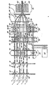
- the apparatus shown in the drawings is an apparatus for the manufacture of a cable core unit from 25 pairs of insulated electrical conductors (or wires as referred to in this description).
- the wires in each pair are stranded together before pairs are themselves combined and bound with binding tape to form the core unit.
- the core unit may be intended to form a complete cable core, or a core may be made from a plurality of such units.
- the apparatus comprises a plurality of wire guide means, one for each pair of conductors.
- Each guide means is in the form of two guide tubes 10, extending one alongside the other, from a tube support plate 12 at their upstream ends to a twisting station at their downstream ends.
- Each tube is individually rotatably mounted about its own axis by its upstream end within the plate support which is, in turn, spring urged upon parallel guides 14 towards a fixed frame member 16.
- the tubes are rotationally flexible for the purpose of withstanding rotational forces involved when downstream ends of the tubes are rotated relative to upstream ends and each at its twisting station, around a longitudinal axis located substantially symmetrically between the tubes.
- the tubes are formed from a material which provides this rotational flexibility and may be made, for instance, from stainless steel or an acetal homopolymer, as sold under the trademark "DELRIN”.
- each guide means and its method of mounting to the frame member 16 are described in detail in Patent application Serial No. , filed concurrently with this present application in the names of John Nicholas Garner and Jean Marc Roberge and entitled “Stranding Wires".
- a direction changing means 18 is provided for each twisting means (to be described) guide means as shown by Figure 1.
- This changing means comprises a magnetic switch means which is triggered by an interrupter arm as described in copending patent application Serial No. , filed concurrently with this present application in the names of John Nicholas Garner, Jean Marc Roberge and Norbert Meilenner and entitled "Apparatus for Stranding Wire".
- each changing means 18 is located a short distance from its associated plate support 12.
- the twenty-five guide means thus included in the apparatus are arranged in specific manner and there are three twisting stations for three groups of the guide means.
- all of the guide means are located by the frame member 16 and other frame members around three pitch circles which are concentric around a common axis 20 as shown by Figure 1.
- three guide means are located upon an innermost pitch circle by the positions of their plate supports 12 which are equally spaced around the common axis 20.
- the tubes of these three guide means extend for approximately 65 feet to the first twisting station 22 at which a twisting means 24 for each of the three guide means is held by a pair of spaced parallel frame members 26, the twisting means being in corresponding positions to the associated plate supports 14 whereby the guide means extend substantially parallel with the axis 20.
- One of the three innermost guide means is superposed by another guide means in Figure 1 so that only two, together with their twisting means, are shown.
- Each twisting means 24, 28, and 36 comprises a cylinder 42 formed with two holes (not shown) within which the downstream ends of the two tubes are secured.
- Two annular electric clutches 44 and 46 have their driven sides secured to the cylinder 42 for driving it alternately in opposite directions. All clutches 44 and 46 are radially aligned into two groups between the frames of each pair 26, 32 and 38 and the clutches in each group are driven by a common drive belt 48 or 50.
- the drive belts 48 and 50 at each twisting station are driven continuously, each in one direction, around pulley wheels 52, 54 secured to two drive shafts 56 (which are in line in Figure 1).
- the drive shafts are driven by a single electric motor 58.
- each tube 60 Downstream of each twisting means 24, 28, a single tube 60 extends, the tube being secured to its cylinder 42 and extending to a downstream end held by a bearing 62 in a frame 64 lying immediately downstream from the twisting station 34.
- These tubes 60 are torsionally rigid, i.e. as they rotate with their twisting means, they do not torsionally twist as does each guide means.
- Each tube 60 is formed from metal or rigid plastic.
- the tubes 60 pass through central apertures 66 of frames 32 and 38 through which they pass towards frame 64.
- Each of the guide means and tubes 60 leading to the frame 64, or in the case of the guide means terminating in the twisting means 36, is to be used to enable each of its wires 68 to be given a degree of twist by the twisting means while the tubes prevent the wires from twisting together.
- the pitch circle for the twisting means 36 is at a diameter only sufficient to allow all of the guide means and twisting means to be passed between and held by the various frames while being suitably drivably connected to the motor 58 without any interference between one twisting means and its guide means and another. Nevertheless, for stranding together twenty-five pairs of wires, the diameter of the outermost pitch circle is approximately 20 inches. However, it is required that the apparatus should provide a cable core unit 72 from these wires.
- the apparatus comprises strand prevention means which follow and maintain converging curved paths although they are caused to rotate in alternating directions together with the twisting means.
- These curved paths direct the twenty-five parallel paths for the wires of the pairs onto a single path which is coincident with the axis 20 at the station 76.
- each strand prevention means comprises a wire separation tube 78.
- each tube 60 terminating at frame 64, the paths for the wires of each pair to be stranded are continued by a separation tube 78 which passes through bearings 80 in a support frame 82 and terminates at a support frame 84 which is disposed immediately upstream of the stranding station 74.
- These tubes 78 are secured to the tubes 60 so as to rotate with them.
- Wire separation tubes 78 are also secured to and extend from the cylinders 42 of twisting means 36, and these tubes 78 pass through clearance holes (not shown) in the frame 64, which lies close to the cylinders 42, and then proceed through bearings 80 to terminate at frame 84.
- the tubes converge as they pass through frame 82 to frame 84 and each tube is held upon its curved path by the frames.
- each tube is required to rotate around its axis which coincides with its fixed curved path section and must have sufficient flexibility to be maintained in this curved configuration while enduring alternating compressive and tensile stresses to give a satisfactory working life.
- Each tube 78 also has torsional rigidity to prevent it from twisting thereby avoiding build-up and retention of twist.
- the tubes 78 of this embodiment are formed from an acetal homopolymer, as sold under the trademark "DELRIN”, and have an outside diameter of 0.22 inches and an inside diameter of 0.075 inches. These tubes pass through the frame 82 to frame 84 at pitch circle diameters which, while decreasing, still maintain the relative positions of the tubes at frame 84. Although the outermost pitch circle diameter is reduced from around 20 inches at frame 64 to approximately 8 inches over a distance of approximately 20 inches along the axis 20, these tubes satisfactorily withstand the stresses involved.
- Another suitable material is stainless steel.
- each hole 86 is formed normal to the frame and an adjustable fitting 88 is located within the hole to provide the desired angle.
- All the fittings 88 are of similar construction and comprise a substantially cylindrical member 90 having a smooth surface portion 92 for sliding reception within its frame hole 86.
- One end of the portion 92 terminates in a larger diameter shoulder 94 to engage one side of the frame.
- the other end of portion 92 extends as a screw thread 96 to accommodate a holding nut 98 to assemble it to the frame.
- the member 90 has a stepped bore 100 which, as shown, is inclined to the axis of the member and this angle is dependent upon whichever pitch circle position the fitting is used.
- the fitting 88 is rotatable in each case, within the frame 82 to adjust the inclination of the bore 100 to the desired smoothly curved path of its tube 78, the fitting then being secured in position.
- each tube 78 is secured by a locking screw 108 within an end 110 of a cylindrical fitting 112.
- This fitting has a reduced diameter portion 114 having a passage sufficient for two wires 68 issuing from the end of tube 78.
- This portion 114 is rotatably received within a short metal cylinder 116 extending through a hole 118 formed in frame 84 at the required angle.
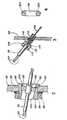
- Each of the separation tubes 78 has two feedpath separation means spaced apart along it to separate the feedpaths for the two wires which are to pass through it.
- Each of the separation means comprises a pin 120, as shown in Figure 4, which is a diagrammatic view of the whole length of one of the tubes and indicates the positions of the two pins which are disposed at its ends.
- each of the twisting means is rotated continuously in alternating directions for a preset number of revolutions (e.g. 35 revolutions to each side of an untwisted position of the guide tubes as shown by Figure 1).
- the downstream end of the associated guide tubes 20 rotate with the twisting means to place torsional twist on the tubes first in one direction and then the other about a longitudinal axis.
- the alternate rotation of the twisting means is effected by the direction changing means 28 which alternately operates the clutches 44 and 46.
- the wires 80 are passed through the tubes 20 which prevent the wires from twisting together as the wires move towards the twisting means.
- the wires pass through the twisting means 36, 38 or 40.
- the wires for each pair passing through its twisting means 24 and 28 Upon the wires for each pair passing through its twisting means 24 and 28, the wires immediately pass from the two tubes 10 into a respective tube 60. These wires then proceed into their separation tubes 78. In each tube 78, the two wires 68 for each pair are fed one either side of each of the pins 120 which thus prevent the wires from stranding together under the action of the twisting means while in the tube 78. The pins 120 also prevent the wires from stranding together during their movement along the tubes 60. The pins 120 in tubes 78 leading from the twisting means 36, also prevent stranding of the wires in these tubes.
- the tubes 78 rotate around the curved paths of their axes while leading the wires along converging paths whereby when the wires issue from the tubes 78, the wires immediately strand together to form the pairs, the pairs then being adjacent one another and moving Into the cable core unit forming station 76.
- This station is sufficiently close to the stranding station 74 to preclude any substantial untwisting of the wires of each pair before the pairs come together as the core unit whereupon any unwinding action is resisted by virtue of their frictional contact.
- the core unit forming station does, in practice, include a device for holding the wire pairs in the form of the core unit.
- a conventional binding head 122 may be used - having a spool 124 of tape which wraps tape 126 around the core unit as it emerges from the head.
- the above apparatus and according to the invention thus enables a core unit to be formed from pairs of wires which have been stranded together with a rotatable twisting means and a torsionally twistable wire guide means with negligible unwinding of the wires in each pair.
- the twisting means are also necessarily spaced and if stranding of the pairs were allowed to take place immediately upon exiting from the twisting means, then uncontrollable unwinding would occur before convergence of the stranded pairs at the core unit forming station.
- this problem is overcome by delaying of the stranding of wires into their pairs until they lie closely adjacent to one another and are positioned for movement directly into the core unit forming station.
- each guide means in the form of two tubes 10 is replaced by a guide means comprising a single tube defining a single axial passage which provides at least two side-by-side feedpaths for wire.
- the passage is shaped to prevent wires from moving across the passage to interchange positions by having a narrow passage region in between wider regions which provide the feed paths.
Landscapes
- Engineering & Computer Science (AREA)
- Manufacturing & Machinery (AREA)
- Wire Processing (AREA)
- Ropes Or Cables (AREA)
- Processes Specially Adapted For Manufacturing Cables (AREA)
Applications Claiming Priority (2)
| Application Number | Priority Date | Filing Date | Title |
|---|---|---|---|
| CA409994 | 1982-08-24 | ||
| CA000409994A CA1174914A (en) | 1982-08-24 | 1982-08-24 | Apparatus for stranding at least two wires together |
Publications (3)
| Publication Number | Publication Date |
|---|---|
| EP0103963A2 true EP0103963A2 (de) | 1984-03-28 |
| EP0103963A3 EP0103963A3 (en) | 1984-08-22 |
| EP0103963B1 EP0103963B1 (de) | 1987-11-04 |
Family
ID=4123469
Family Applications (1)
| Application Number | Title | Priority Date | Filing Date |
|---|---|---|---|
| EP83304424A Expired EP0103963B1 (de) | 1982-08-24 | 1983-08-01 | Apparat zum miteinander Verseilen von wenigstens zwei Drähten |
Country Status (5)
| Country | Link |
|---|---|
| EP (1) | EP0103963B1 (de) |
| JP (1) | JPS5954435A (de) |
| CA (1) | CA1174914A (de) |
| DE (1) | DE3374361D1 (de) |
| FI (1) | FI72831C (de) |
Cited By (3)
| Publication number | Priority date | Publication date | Assignee | Title |
|---|---|---|---|---|
| WO1987006050A1 (en) * | 1986-04-01 | 1987-10-08 | Oy Nokia Ab | Alternate reverse twisting method and apparatus both alternate reversely twisted product |
| WO1998006155A1 (de) * | 1996-08-06 | 1998-02-12 | Gluth Systemtechnik Gmbh | Verfahren und verdrillvorrichtung zum verdrillen von mindestens zwei einzelleitungen |
| WO2004082575A3 (en) * | 2003-03-18 | 2005-01-27 | Bayer Healthcare Ag | Diagnostics and therapeutics for diseases associated with phosphodiesterase 6b (pde6b) |
Family Cites Families (3)
| Publication number | Priority date | Publication date | Assignee | Title |
|---|---|---|---|---|
| US3732682A (en) * | 1971-06-29 | 1973-05-15 | Western Electric Co | Methods of and apparatus for twisting and stranding cable pairs in a tandem operation |
| US3847190A (en) * | 1972-12-19 | 1974-11-12 | Phillips Cable Ltd | Method and apparatus for twisting wires |
| US3910022A (en) * | 1974-07-18 | 1975-10-07 | Northern Electric Co | Apparatus for stranding wires |
-
1982
- 1982-08-24 CA CA000409994A patent/CA1174914A/en not_active Expired
-
1983
- 1983-08-01 EP EP83304424A patent/EP0103963B1/de not_active Expired
- 1983-08-01 DE DE8383304424T patent/DE3374361D1/de not_active Expired
- 1983-08-22 JP JP58151733A patent/JPS5954435A/ja active Pending
- 1983-08-23 FI FI833013A patent/FI72831C/fi not_active IP Right Cessation
Cited By (5)
| Publication number | Priority date | Publication date | Assignee | Title |
|---|---|---|---|---|
| WO1987006050A1 (en) * | 1986-04-01 | 1987-10-08 | Oy Nokia Ab | Alternate reverse twisting method and apparatus both alternate reversely twisted product |
| US4974408A (en) * | 1986-04-01 | 1990-12-04 | Oy Nokia Ab | Alternate reverse twisting method and apparatus |
| WO1998006155A1 (de) * | 1996-08-06 | 1998-02-12 | Gluth Systemtechnik Gmbh | Verfahren und verdrillvorrichtung zum verdrillen von mindestens zwei einzelleitungen |
| US6167919B1 (en) | 1996-08-06 | 2001-01-02 | Gluth Systemtechnik Gmbh | Method and device for the twisting of at least two single-lines |
| WO2004082575A3 (en) * | 2003-03-18 | 2005-01-27 | Bayer Healthcare Ag | Diagnostics and therapeutics for diseases associated with phosphodiesterase 6b (pde6b) |
Also Published As
| Publication number | Publication date |
|---|---|
| DE3374361D1 (en) | 1987-12-10 |
| FI72831C (fi) | 1987-07-10 |
| FI72831B (fi) | 1987-03-31 |
| JPS5954435A (ja) | 1984-03-29 |
| FI833013A0 (fi) | 1983-08-23 |
| CA1174914A (en) | 1984-09-25 |
| FI833013L (fi) | 1984-02-25 |
| EP0103963A3 (en) | 1984-08-22 |
| EP0103963B1 (de) | 1987-11-04 |
Similar Documents
| Publication | Publication Date | Title |
|---|---|---|
| US4426839A (en) | Stranding wires | |
| US20100044408A1 (en) | Twisted pair cable feeding mechanism and method | |
| US4429520A (en) | Apparatus for stranding at least two wires together | |
| US4414802A (en) | Apparatus for stranding wire | |
| EP0103963B1 (de) | Apparat zum miteinander Verseilen von wenigstens zwei Drähten | |
| US4704855A (en) | Wire twisting device | |
| US4328664A (en) | Apparatus for the SZ-twisting of stranding elements of electric or optical cables and lines | |
| US4300339A (en) | System for stranding and cabling elongate filaments | |
| CA1174911A (en) | Forming cable core units | |
| US4429519A (en) | Forming cable core units | |
| EP0031081B1 (de) | Apparat zum Verseilen von Drähten | |
| US4288976A (en) | Apparatus for the SZ-twisting of power cable conductors with sector-shaped conductor cross section | |
| CA1146026A (en) | Stranding stock of large cross sections | |
| US4426837A (en) | Apparatus for stranding wire | |
| GB1592462A (en) | Twining and cabling apparatus | |
| US4590754A (en) | Forming cable core units | |
| CA1174915A (en) | Stranding wires | |
| EP0461844B1 (de) | Verbesserungen an Vorseilmaschinen | |
| FI79417B (fi) | Bildande av kabelkaernenheter. | |
| CA1227705A (en) | Apparatus and method of making metallic cord | |
| CA1174912A (en) | Apparatus for stranding wire | |
| JP3097995B2 (ja) | テープ心線の落し込み装置 | |
| CA1261688A (en) | Twin track buncher | |
| US6434922B2 (en) | Track sliding facilitating method and device for a wire stranding machine | |
| WO1999063147A1 (en) | Cable twist setting method and apparatus |
Legal Events
| Date | Code | Title | Description |
|---|---|---|---|
| PUAI | Public reference made under article 153(3) epc to a published international application that has entered the european phase |
Free format text: ORIGINAL CODE: 0009012 |
|
| AK | Designated contracting states |
Designated state(s): CH DE FR GB IT LI NL SE |
|
| PUAL | Search report despatched |
Free format text: ORIGINAL CODE: 0009013 |
|
| AK | Designated contracting states |
Designated state(s): CH DE FR GB IT LI NL SE |
|
| 17P | Request for examination filed |
Effective date: 19850125 |
|
| 17Q | First examination report despatched |
Effective date: 19860317 |
|
| GRAA | (expected) grant |
Free format text: ORIGINAL CODE: 0009210 |
|
| AK | Designated contracting states |
Kind code of ref document: B1 Designated state(s): CH DE FR GB IT LI NL SE |
|
| ITF | It: translation for a ep patent filed | ||
| REF | Corresponds to: |
Ref document number: 3374361 Country of ref document: DE Date of ref document: 19871210 |
|
| ET | Fr: translation filed | ||
| PLBE | No opposition filed within time limit |
Free format text: ORIGINAL CODE: 0009261 |
|
| STAA | Information on the status of an ep patent application or granted ep patent |
Free format text: STATUS: NO OPPOSITION FILED WITHIN TIME LIMIT |
|
| 26N | No opposition filed | ||
| PG25 | Lapsed in a contracting state [announced via postgrant information from national office to epo] |
Ref country code: GB Effective date: 19890801 |
|
| PG25 | Lapsed in a contracting state [announced via postgrant information from national office to epo] |
Ref country code: SE Effective date: 19890802 |
|
| PG25 | Lapsed in a contracting state [announced via postgrant information from national office to epo] |
Ref country code: LI Effective date: 19890831 Ref country code: CH Effective date: 19890831 |
|
| PG25 | Lapsed in a contracting state [announced via postgrant information from national office to epo] |
Ref country code: NL Effective date: 19900301 |
|
| GBPC | Gb: european patent ceased through non-payment of renewal fee | ||
| NLV4 | Nl: lapsed or anulled due to non-payment of the annual fee | ||
| PG25 | Lapsed in a contracting state [announced via postgrant information from national office to epo] |
Ref country code: FR Effective date: 19900427 |
|
| REG | Reference to a national code |
Ref country code: CH Ref legal event code: PL |
|
| PG25 | Lapsed in a contracting state [announced via postgrant information from national office to epo] |
Ref country code: DE Effective date: 19900501 |
|
| REG | Reference to a national code |
Ref country code: FR Ref legal event code: ST |
|
| PGFP | Annual fee paid to national office [announced via postgrant information from national office to epo] |
Ref country code: LU Payment date: 19940731 Year of fee payment: 12 |
|
| EPTA | Lu: last paid annual fee | ||
| EUG | Se: european patent has lapsed |
Ref document number: 83304424.1 Effective date: 19900418 |