EP0104190B1 - Procede et dispositif pour le scellement etanche de recipients en forme de cuvette avec une feuille ou analogue - Google Patents
Procede et dispositif pour le scellement etanche de recipients en forme de cuvette avec une feuille ou analogue Download PDFInfo
- Publication number
- EP0104190B1 EP0104190B1 EP19830900924 EP83900924A EP0104190B1 EP 0104190 B1 EP0104190 B1 EP 0104190B1 EP 19830900924 EP19830900924 EP 19830900924 EP 83900924 A EP83900924 A EP 83900924A EP 0104190 B1 EP0104190 B1 EP 0104190B1
- Authority
- EP
- European Patent Office
- Prior art keywords
- support
- container
- heating installation
- workpiece
- drive unit
- Prior art date
- Legal status (The legal status is an assumption and is not a legal conclusion. Google has not performed a legal analysis and makes no representation as to the accuracy of the status listed.)
- Expired
Links
- 238000007789 sealing Methods 0.000 title claims abstract description 15
- 238000000034 method Methods 0.000 title claims abstract description 12
- 238000010438 heat treatment Methods 0.000 claims abstract description 44
- 230000005672 electromagnetic field Effects 0.000 claims abstract description 12
- 239000011888 foil Substances 0.000 claims description 5
- 230000001681 protective effect Effects 0.000 claims description 5
- 229910000831 Steel Inorganic materials 0.000 claims description 4
- 239000010959 steel Substances 0.000 claims description 4
- 238000009434 installation Methods 0.000 claims 10
- 230000001105 regulatory effect Effects 0.000 claims 6
- 238000009877 rendering Methods 0.000 claims 1
- 238000010276 construction Methods 0.000 abstract description 3
- 230000000694 effects Effects 0.000 abstract description 2
- 238000010586 diagram Methods 0.000 description 2
- 239000004033 plastic Substances 0.000 description 2
- 241001295925 Gegenes Species 0.000 description 1
- 238000003780 insertion Methods 0.000 description 1
- 230000037431 insertion Effects 0.000 description 1
- 239000000463 material Substances 0.000 description 1
- 239000002184 metal Substances 0.000 description 1
- 239000002985 plastic film Substances 0.000 description 1
- 229920006255 plastic film Polymers 0.000 description 1
- 230000000284 resting effect Effects 0.000 description 1
- 230000001960 triggered effect Effects 0.000 description 1
Images


Classifications
-
- B—PERFORMING OPERATIONS; TRANSPORTING
- B65—CONVEYING; PACKING; STORING; HANDLING THIN OR FILAMENTARY MATERIAL
- B65B—MACHINES, APPARATUS OR DEVICES FOR, OR METHODS OF, PACKAGING ARTICLES OR MATERIALS; UNPACKING
- B65B51/00—Devices for, or methods of, sealing or securing package folds or closures; Devices for gathering or twisting wrappers, or necks of bags
- B65B51/10—Applying or generating heat or pressure or combinations thereof
- B65B51/14—Applying or generating heat or pressure or combinations thereof by reciprocating or oscillating members
-
- B—PERFORMING OPERATIONS; TRANSPORTING
- B29—WORKING OF PLASTICS; WORKING OF SUBSTANCES IN A PLASTIC STATE IN GENERAL
- B29C—SHAPING OR JOINING OF PLASTICS; SHAPING OF MATERIAL IN A PLASTIC STATE, NOT OTHERWISE PROVIDED FOR; AFTER-TREATMENT OF THE SHAPED PRODUCTS, e.g. REPAIRING
- B29C65/00—Joining or sealing of preformed parts, e.g. welding of plastics materials; Apparatus therefor
- B29C65/02—Joining or sealing of preformed parts, e.g. welding of plastics materials; Apparatus therefor by heating, with or without pressure
-
- B—PERFORMING OPERATIONS; TRANSPORTING
- B29—WORKING OF PLASTICS; WORKING OF SUBSTANCES IN A PLASTIC STATE IN GENERAL
- B29C—SHAPING OR JOINING OF PLASTICS; SHAPING OF MATERIAL IN A PLASTIC STATE, NOT OTHERWISE PROVIDED FOR; AFTER-TREATMENT OF THE SHAPED PRODUCTS, e.g. REPAIRING
- B29C66/00—General aspects of processes or apparatus for joining preformed parts
- B29C66/01—General aspects dealing with the joint area or with the area to be joined
- B29C66/05—Particular design of joint configurations
- B29C66/10—Particular design of joint configurations particular design of the joint cross-sections
- B29C66/11—Joint cross-sections comprising a single joint-segment, i.e. one of the parts to be joined comprising a single joint-segment in the joint cross-section
- B29C66/112—Single lapped joints
-
- B—PERFORMING OPERATIONS; TRANSPORTING
- B29—WORKING OF PLASTICS; WORKING OF SUBSTANCES IN A PLASTIC STATE IN GENERAL
- B29C—SHAPING OR JOINING OF PLASTICS; SHAPING OF MATERIAL IN A PLASTIC STATE, NOT OTHERWISE PROVIDED FOR; AFTER-TREATMENT OF THE SHAPED PRODUCTS, e.g. REPAIRING
- B29C66/00—General aspects of processes or apparatus for joining preformed parts
- B29C66/01—General aspects dealing with the joint area or with the area to be joined
- B29C66/05—Particular design of joint configurations
- B29C66/10—Particular design of joint configurations particular design of the joint cross-sections
- B29C66/13—Single flanged joints; Fin-type joints; Single hem joints; Edge joints; Interpenetrating fingered joints; Other specific particular designs of joint cross-sections not provided for in groups B29C66/11 - B29C66/12
- B29C66/131—Single flanged joints, i.e. one of the parts to be joined being rigid and flanged in the joint area
-
- B—PERFORMING OPERATIONS; TRANSPORTING
- B29—WORKING OF PLASTICS; WORKING OF SUBSTANCES IN A PLASTIC STATE IN GENERAL
- B29C—SHAPING OR JOINING OF PLASTICS; SHAPING OF MATERIAL IN A PLASTIC STATE, NOT OTHERWISE PROVIDED FOR; AFTER-TREATMENT OF THE SHAPED PRODUCTS, e.g. REPAIRING
- B29C66/00—General aspects of processes or apparatus for joining preformed parts
- B29C66/50—General aspects of joining tubular articles; General aspects of joining long products, i.e. bars or profiled elements; General aspects of joining single elements to tubular articles, hollow articles or bars; General aspects of joining several hollow-preforms to form hollow or tubular articles
- B29C66/51—Joining tubular articles, profiled elements or bars; Joining single elements to tubular articles, hollow articles or bars; Joining several hollow-preforms to form hollow or tubular articles
- B29C66/53—Joining single elements to tubular articles, hollow articles or bars
- B29C66/534—Joining single elements to open ends of tubular or hollow articles or to the ends of bars
- B29C66/5346—Joining single elements to open ends of tubular or hollow articles or to the ends of bars said single elements being substantially flat
- B29C66/53461—Joining single elements to open ends of tubular or hollow articles or to the ends of bars said single elements being substantially flat joining substantially flat covers and/or substantially flat bottoms to open ends of container bodies
-
- B—PERFORMING OPERATIONS; TRANSPORTING
- B29—WORKING OF PLASTICS; WORKING OF SUBSTANCES IN A PLASTIC STATE IN GENERAL
- B29C—SHAPING OR JOINING OF PLASTICS; SHAPING OF MATERIAL IN A PLASTIC STATE, NOT OTHERWISE PROVIDED FOR; AFTER-TREATMENT OF THE SHAPED PRODUCTS, e.g. REPAIRING
- B29C66/00—General aspects of processes or apparatus for joining preformed parts
- B29C66/80—General aspects of machine operations or constructions and parts thereof
- B29C66/82—Pressure application arrangements, e.g. transmission or actuating mechanisms for joining tools or clamps
- B29C66/824—Actuating mechanisms
- B29C66/8244—Actuating mechanisms magnetically driven
-
- B—PERFORMING OPERATIONS; TRANSPORTING
- B29—WORKING OF PLASTICS; WORKING OF SUBSTANCES IN A PLASTIC STATE IN GENERAL
- B29C—SHAPING OR JOINING OF PLASTICS; SHAPING OF MATERIAL IN A PLASTIC STATE, NOT OTHERWISE PROVIDED FOR; AFTER-TREATMENT OF THE SHAPED PRODUCTS, e.g. REPAIRING
- B29C66/00—General aspects of processes or apparatus for joining preformed parts
- B29C66/80—General aspects of machine operations or constructions and parts thereof
- B29C66/83—General aspects of machine operations or constructions and parts thereof characterised by the movement of the joining or pressing tools
- B29C66/832—Reciprocating joining or pressing tools
- B29C66/8322—Joining or pressing tools reciprocating along one axis
-
- B—PERFORMING OPERATIONS; TRANSPORTING
- B29—WORKING OF PLASTICS; WORKING OF SUBSTANCES IN A PLASTIC STATE IN GENERAL
- B29C—SHAPING OR JOINING OF PLASTICS; SHAPING OF MATERIAL IN A PLASTIC STATE, NOT OTHERWISE PROVIDED FOR; AFTER-TREATMENT OF THE SHAPED PRODUCTS, e.g. REPAIRING
- B29C66/00—General aspects of processes or apparatus for joining preformed parts
- B29C66/80—General aspects of machine operations or constructions and parts thereof
- B29C66/84—Specific machine types or machines suitable for specific applications
- B29C66/861—Hand-held tools
-
- B—PERFORMING OPERATIONS; TRANSPORTING
- B29—WORKING OF PLASTICS; WORKING OF SUBSTANCES IN A PLASTIC STATE IN GENERAL
- B29C—SHAPING OR JOINING OF PLASTICS; SHAPING OF MATERIAL IN A PLASTIC STATE, NOT OTHERWISE PROVIDED FOR; AFTER-TREATMENT OF THE SHAPED PRODUCTS, e.g. REPAIRING
- B29C66/00—General aspects of processes or apparatus for joining preformed parts
- B29C66/90—Measuring or controlling the joining process
- B29C66/94—Measuring or controlling the joining process by measuring or controlling the time
- B29C66/944—Measuring or controlling the joining process by measuring or controlling the time by controlling or regulating the time
-
- B—PERFORMING OPERATIONS; TRANSPORTING
- B65—CONVEYING; PACKING; STORING; HANDLING THIN OR FILAMENTARY MATERIAL
- B65B—MACHINES, APPARATUS OR DEVICES FOR, OR METHODS OF, PACKAGING ARTICLES OR MATERIALS; UNPACKING
- B65B7/00—Closing containers or receptacles after filling
- B65B7/16—Closing semi-rigid or rigid containers or receptacles not deformed by, or not taking-up shape of, contents, e.g. boxes or cartons
- B65B7/28—Closing semi-rigid or rigid containers or receptacles not deformed by, or not taking-up shape of, contents, e.g. boxes or cartons by applying separate preformed closures, e.g. lids, covers
- B65B7/2842—Securing closures on containers
- B65B7/2878—Securing closures on containers by heat-sealing
-
- B—PERFORMING OPERATIONS; TRANSPORTING
- B29—WORKING OF PLASTICS; WORKING OF SUBSTANCES IN A PLASTIC STATE IN GENERAL
- B29C—SHAPING OR JOINING OF PLASTICS; SHAPING OF MATERIAL IN A PLASTIC STATE, NOT OTHERWISE PROVIDED FOR; AFTER-TREATMENT OF THE SHAPED PRODUCTS, e.g. REPAIRING
- B29C66/00—General aspects of processes or apparatus for joining preformed parts
- B29C66/80—General aspects of machine operations or constructions and parts thereof
- B29C66/82—Pressure application arrangements, e.g. transmission or actuating mechanisms for joining tools or clamps
- B29C66/822—Transmission mechanisms
- B29C66/8227—Transmission mechanisms using springs
-
- B—PERFORMING OPERATIONS; TRANSPORTING
- B29—WORKING OF PLASTICS; WORKING OF SUBSTANCES IN A PLASTIC STATE IN GENERAL
- B29C—SHAPING OR JOINING OF PLASTICS; SHAPING OF MATERIAL IN A PLASTIC STATE, NOT OTHERWISE PROVIDED FOR; AFTER-TREATMENT OF THE SHAPED PRODUCTS, e.g. REPAIRING
- B29C66/00—General aspects of processes or apparatus for joining preformed parts
- B29C66/90—Measuring or controlling the joining process
- B29C66/91—Measuring or controlling the joining process by measuring or controlling the temperature, the heat or the thermal flux
-
- B—PERFORMING OPERATIONS; TRANSPORTING
- B29—WORKING OF PLASTICS; WORKING OF SUBSTANCES IN A PLASTIC STATE IN GENERAL
- B29C—SHAPING OR JOINING OF PLASTICS; SHAPING OF MATERIAL IN A PLASTIC STATE, NOT OTHERWISE PROVIDED FOR; AFTER-TREATMENT OF THE SHAPED PRODUCTS, e.g. REPAIRING
- B29C66/00—General aspects of processes or apparatus for joining preformed parts
- B29C66/90—Measuring or controlling the joining process
- B29C66/92—Measuring or controlling the joining process by measuring or controlling the pressure, the force, the mechanical power or the displacement of the joining tools
- B29C66/924—Measuring or controlling the joining process by measuring or controlling the pressure, the force, the mechanical power or the displacement of the joining tools by controlling or regulating the pressure, the force, the mechanical power or the displacement of the joining tools
- B29C66/9241—Measuring or controlling the joining process by measuring or controlling the pressure, the force, the mechanical power or the displacement of the joining tools by controlling or regulating the pressure, the force, the mechanical power or the displacement of the joining tools by controlling or regulating the pressure, the force or the mechanical power
-
- B—PERFORMING OPERATIONS; TRANSPORTING
- B29—WORKING OF PLASTICS; WORKING OF SUBSTANCES IN A PLASTIC STATE IN GENERAL
- B29C—SHAPING OR JOINING OF PLASTICS; SHAPING OF MATERIAL IN A PLASTIC STATE, NOT OTHERWISE PROVIDED FOR; AFTER-TREATMENT OF THE SHAPED PRODUCTS, e.g. REPAIRING
- B29C66/00—General aspects of processes or apparatus for joining preformed parts
- B29C66/90—Measuring or controlling the joining process
- B29C66/94—Measuring or controlling the joining process by measuring or controlling the time
- B29C66/949—Measuring or controlling the joining process by measuring or controlling the time characterised by specific time values or ranges
-
- B—PERFORMING OPERATIONS; TRANSPORTING
- B65—CONVEYING; PACKING; STORING; HANDLING THIN OR FILAMENTARY MATERIAL
- B65B—MACHINES, APPARATUS OR DEVICES FOR, OR METHODS OF, PACKAGING ARTICLES OR MATERIALS; UNPACKING
- B65B51/00—Devices for, or methods of, sealing or securing package folds or closures; Devices for gathering or twisting wrappers, or necks of bags
- B65B51/10—Applying or generating heat or pressure or combinations thereof
- B65B2051/105—Heat seal temperature control
Definitions
- the invention relates to a method for sealing bowl-shaped containers with a film or the like, wherein a heating device with a radiator is pressed onto the container with a film or the like placed on it, the heating device is arranged on a support and a workpiece is switched on between the heating device and the support and between Carrier and workpiece an electromagnetic field is built up, and a device therefor.
- Manually operated sealing devices are also known, in which the heating element is lowered onto the container to be sealed by means of a bracket and a joint. These machines are also available in small format, for example for retail. However, it has the disadvantage that neither the duration of the pressure nor the pressure itself is kept constant, so that the sealing quality is not constant. They also affect operational and occupational safety. Furthermore, they can only generate a pressure of about 100 kg.
- Lifting magnets are generally used in the construction of machines in which it is important to move a pressure stamp or the like. If the printing capacity of such a machine is to remain the same when the carrier plate and the other plate, between which the electromagnetic field is building up, are removed, the lifting device must have a certain size or the voltage applied must be continuously increased. That is why machines with solenoids are designed to be large in size and of complex construction.
- Electromagnets are also used, for example according to CH-A-258 372. There the electromagnet moves two heatable jaws to one another and foil strips inserted between them are sealed to one another. In practice, plastic bags, for example for frozen goods, are sealed.
- this device or method according to CH-A-258 372 is not applicable to the sealing of bowl-shaped containers with a film or the like.
- the bowl-shaped container would be destroyed by the pressure.
- the inventor has set himself the task of developing a method and a device for sealing bowl-shaped containers, the device only being started by a container to be sealed.
- the device for this should be simple and thus as inexpensive as possible and should have a small format so that it can also be used, for example, in retail.
- a method of the above leads to the solution of this task.
- Type in which the container is placed in a receiving part and moved on a rail under the heating device, where a switch is actuated which stimulates the build-up of the electromagnetic field.
- This configuration of the method according to the invention has the simple effect that the entire device is only put into operation when the container to be sealed is brought into the correct position. At the same time, the insertion of the container into the receiving part outside of the heating device is facilitated. A bowl-shaped container is not destroyed.
- An improvement of the method according to the invention provides that the duration of the pressing from the radiator onto the container and the level of the voltage applied to the drive unit is determined via a time control unit.
- the voltage applied to the drive unit and thus the pressing pressure can also be increased via the time control unit after the radiator has been placed on the container. This ensures that the radiator does not hit the receiving part with the full pressing force when lowering and damages it.
- the heating device is arranged between two columns spanned by a crossmember and under this heating device a rail for guiding the containers in a receiving part and a switch are provided which stimulate the build-up of the electromagnetic field when actuated by the container.
- the rail consists of a spring which engages with a groove in the receiving part.
- the carrier and workpiece consist of two metal plates, one or both of which are applied with voltage. With a diameter of approximately 10 cm, the machine was able to generate a pressure of approximately 400 kg.
- the carrier and the workpiece are accommodated in two parts of a protective cover, the cross-member of which, furthermore, contains the part containing the carrier so that it can be guided over the part containing the workpiece, which is fixed on the upper side of the cross-member.
- a protective cover the cross-member of which, furthermore, contains the part containing the carrier so that it can be guided over the part containing the workpiece, which is fixed on the upper side of the cross-member.
- the heating device which can be moved up and down between the two columns, is preferably attached to an energy store Coil springs on the crossbar. These energy stores counteract the attraction of the electromagnetic field. However, it is also within the scope of the invention that these energy stores are dispensed with and the heating element is returned to the starting position by reversing the polarity of the drive device, so that the support and the workpiece repel each other. In addition to the possibility of producing this machine in the smallest format, the simplicity of the drive and thus the low costs should be noted. This makes it possible, for example, for retail stores that only need a small number of containers to be sealed per day to use this machine.
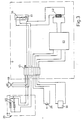
- the heating device, the drive unit, the pressure switch and a toggle switch, a transformer and a time control unit are connected to one another in a control circuit.
- the toggle switch By switching on the toggle switch, both the heating device and - connected via the transformer and the subsequent time control unit - the drive unit are energized, but the drive unit is only actuated when the pressure switch is triggered.
- time control unit determines the duration of the lowering of the heating device. It should preferably have a switchover which, after the heating device has been lowered onto the container, increases the voltage in the drive unit and thus increases the pressure on the container.
- the voltage to be applied to the drive unit depends on. a. also according to the material of the goods to be sealed. Plastic requires less pressure and therefore less tension than, for example, cardboard.
- the invention therefore provides a switch by means of which the transformer can be switched to a higher output power.
- the heating device is preferably equipped with two heating cartridges.
- the machine has a length of approximately 40 cm, a width of approximately 30 cm and a height of approximately 40 cm.
- a threaded spindle is preferably screwed into a holder for the heating device, on which the carrier and a cap nut are screwed on at the other end.
- a device S in particular for sealing container B - shown in dashed lines in FIGS. 1 and 2 - has a supporting housing 1, on the longitudinal sides 2 of which a gate-like framework 4 spanning the housing top 3 consisting of two columns 5 and 6 and a cross member 7 by means of screws 8 is set.
- a rail 10 is arranged on the housing top 3, which with a
- Groove 11 is engaged, which is formed in the bottom 12 of a drawer 15.
- the container B is stored in this drawer 15, its outwardly bent edge edges 16 resting on the top 17 of the drawer 15.
- the drawer 15 can be moved along the longitudinal axis of the housing 1. If it is moved in the direction x (FIG. 2), it passes between the two columns 5 and 6 of the frame 4 and strikes a pressure switch 20 which is fixed to an adjusting block 21.
- a holder 49 for a heating device 25 consisting of a heating element 26 and a covering 27 that extends downward and overlaps it.
- Both the coil springs 23 and the square 24 drill through Traverse 7.
- the coil springs 23 are guided in sleeves 28 and fastened to the bottom of the sleeve (not shown).
- a protective sleeve 31 which consists of a lower part 31 a seated on the cross member 7 and an upper part 31 b overlapping this.
- a cap nut 33 is located on the bottom 32 of the upper part 31.
- a feed line 35 is provided which leads to a toggle switch 36.
- 37 denotes a line to the drive device 30 and 38 denotes a line to the heating device 25 provided with a heat-resistant jacket.
- the control of the device S can be seen from the block diagram according to FIG. 3.
- the usual power network is tapped by a power plug 40.
- both the heating device 25 and a transformer 42 and, following this, a time controller 43 and the drive device 30 are supplied with energy.
- the heating device 25 includes, for example, two heating cartridges 44, each with 600 W.
- a magnetic plate 48 is arranged on the cross member 7 and connected to it by screws (not shown).
- the magnet 48 has an opening 50 in the middle as a passage for the square 24, which is firmly connected via a threaded spindle 51 to a steel plate 52 or the cap nut 33. If voltage is applied to this device, an electromagnetic field builds up between the two plates 48 and 52, the upper plate in the movable part 31 b of the protective cover 31 being attracted to the magnet 48 fixed to the cross member 7 and the square in the opening 50 hanging down on the threaded spindle 51 slides when both magnetic plates are polarized differently. If they have the same polarity, both parts repel each other.
- the device S then operates as follows:
- both the heating device 25 and the electronic parts such as transformer 42 and time controller 43 are supplied with energy.
- the heating time of the radiator 26 is about 3 minutes.
- a container B to be sealed is then placed in the drawer 15 and provided with a cover to be sealed, for example a plastic film or a cardboard plate. Then the drawer 15, guided on the rail 10, is moved against the adjusting block 21 and the pressure switch 20 is actuated.
- a cover to be sealed for example a plastic film or a cardboard plate.
- the latter switches off the energy supply to the electromagnets and the heating device 25 is raised into the starting position by the energy stores 23.
- the drawer 15 can now be pushed back and the sealed container can be removed.
Landscapes
- Engineering & Computer Science (AREA)
- Mechanical Engineering (AREA)
- Package Closures (AREA)
- Closing Of Containers (AREA)
Claims (10)
que le récipient sera placé dans un support (15) et déplacé le long d'une glissière (10) sous le dispositif de chauffage (25) où un commutateur (20) sera actionné déclenchant la formation du champ électromagnétique.
appliquée au système de mise en mouvement (30) donnée par le temporisateur, et de ce fait la pression effectuée sur le récipient (B) sera augmentée, lorsque l'élément chauffant (26) reposera sur celui-ci.
correspondant à un support (52) placé entre deux colonnes (5,6) reliées par une traverse (7) de telle façon qu'entre le dispositif de chauffage (25) et le support (52) se trouve un élément (48) et qu'un champ électromagnétique peut âtre crée entre ce support (52) et cet élément (48), caractérisé par le fait que sous le dispositif de chauffage (25) se trouve une glissière (10) servant à guider le recipient (B) placé dans un support (15), ainsi qu'un commutateur (20) lequel actionné par le recipient (B) commande la formation du champ électromagnétique.
revendications 4 ou 5, par le fait que le support et l'élément correspondant constituant le dispositif de mise en mouvement (30 sont montrés dans un carter en deux parties (31 a et 31 b) et que la partie 31 b contenant le support constitué d'une placé d'acier (52) est mobile et se trouve placée au dessus de la partie (31 a) contenant l'élément constitué d'un aimant (4B), cette dernière étant fixée sur la partie supérieure de la traverse (7).
revendications 4 à 6 par le fait que la distance entre la plaque d'acier (52) et l'aimant (48) est réglable dans sa position de départ au moyen d'un pivot fileté (51) et d'un écrou à capuchon (33) et que le retour dans la position de départ s'effectue par une alimentation électrique de mâme polarité de la plaque d'acier (52) et de l'aimant (48).
revendications de 4 à 7 par le fait que le dispositif de chauffage (25), le système de mise en mouvement (30), le commutateur â poussoir (20) ainsi que l'interrupteur (36), le transformateur (42) et le temporisateur (43) sont reliés entr'eux par un circuit de réglage et que, le cas échéant, par l'intermédiaire de 1,in-terrupteur (36) aussi bien le dispositif de chauffage (25) que le temporisateur (43) et le système de mise en mouvement (30) reliés par l'intermédiaire du transformateur (42) seront alimentés en courant.
Priority Applications (1)
| Application Number | Priority Date | Filing Date | Title |
|---|---|---|---|
| AT83900924T ATE18166T1 (de) | 1982-03-23 | 1983-03-22 | Verfahren und vorrichtung zum versiegeln von schalenfoermigen behaeltern mit einer folie od. dgl. |
Applications Claiming Priority (2)
| Application Number | Priority Date | Filing Date | Title |
|---|---|---|---|
| DE3210566 | 1982-03-23 | ||
| DE19823210566 DE3210566A1 (de) | 1982-03-23 | 1982-03-23 | Verfahren zum bewegen eines an einem traeger festgelegten koerpers |
Publications (2)
| Publication Number | Publication Date |
|---|---|
| EP0104190A1 EP0104190A1 (fr) | 1984-04-04 |
| EP0104190B1 true EP0104190B1 (fr) | 1986-02-26 |
Family
ID=6159031
Family Applications (1)
| Application Number | Title | Priority Date | Filing Date |
|---|---|---|---|
| EP19830900924 Expired EP0104190B1 (fr) | 1982-03-23 | 1983-03-22 | Procede et dispositif pour le scellement etanche de recipients en forme de cuvette avec une feuille ou analogue |
Country Status (5)
| Country | Link |
|---|---|
| US (1) | US4583350A (fr) |
| EP (1) | EP0104190B1 (fr) |
| JP (1) | JPS59500467A (fr) |
| DE (2) | DE3210566A1 (fr) |
| WO (1) | WO1983003397A1 (fr) |
Cited By (1)
| Publication number | Priority date | Publication date | Assignee | Title |
|---|---|---|---|---|
| RU208142U1 (ru) * | 2021-08-10 | 2021-12-06 | Акционерное общество "ТАУРАС-ФЕНИКС" | Устройство с ручным управлением для термической укупорки тары платинкой |
Families Citing this family (22)
| Publication number | Priority date | Publication date | Assignee | Title |
|---|---|---|---|---|
| DE3243634A1 (de) * | 1982-11-25 | 1984-06-14 | Aldo 8200 Schaffhausen Artusi | Vorrichtung zum aufsiegeln einer folie od. dgl. auf einen behaelter |
| FR2603227B1 (fr) * | 1986-08-27 | 1989-02-03 | Seimap | Machine de soudage par ultrasons de films de matiere thermoplastique. |
| US4776150A (en) * | 1986-12-31 | 1988-10-11 | Siegel Harold B | Sealing apparatus |
| US4941306A (en) * | 1988-10-07 | 1990-07-17 | Continental Can Company, Inc. | Apparatus and method for sealing a lid onto a container |
| US5025123A (en) * | 1988-10-07 | 1991-06-18 | Continental Can Company, Inc. | Apparatus and method for sealing a lid onto a container |
| US4996826A (en) * | 1988-10-07 | 1991-03-05 | Continental Can Company, Inc. | Apparatus and method for sealing a lid onto a container |
| US4984414A (en) * | 1988-10-07 | 1991-01-15 | Continental Can Company, Inc. | Apparatus and method for sealing a lid onto a container |
| US5272854A (en) * | 1992-12-04 | 1993-12-28 | Ye E Fu | Packaging mechanism |
| US6499271B1 (en) * | 1996-04-08 | 2002-12-31 | Oliver Products Company | Tray sealing machine |
| US6571534B2 (en) * | 1996-04-08 | 2003-06-03 | Oliver Products Company | Tray sealing machine |
| US5784858A (en) * | 1996-04-08 | 1998-07-28 | Oliver Products Company | Drawer action tray sealing machine |
| EP0855264A1 (fr) * | 1997-01-27 | 1998-07-29 | Novartis AG | Procédé et appareil pour le soudage d'une feuille de couverture sur la base d'un récipient d'emballage ainsi qu'un procédé et appareil pour l'emballage de lentilles de contact |
| US5791120A (en) * | 1997-06-02 | 1998-08-11 | Oliver Products Company | Tray sealing platen and seal apparatus |
| FR2835806B1 (fr) * | 2002-02-12 | 2004-11-19 | Noel Beche | Machine pour la fermeture par thermoscellage de contenants divers |
| US20030217532A1 (en) * | 2002-02-28 | 2003-11-27 | Warlock Productions, Inc. | Manual compact disc jewel case overwrapper |
| FR2908739B1 (fr) * | 2006-11-17 | 2009-02-13 | Ora Sarl | Machine d'operculage |
| US7614202B2 (en) * | 2007-11-27 | 2009-11-10 | Atlas Vac Machine Co., Llc | Sealer and interchangeable tooling therefor |
| FR2938507B1 (fr) | 2008-11-14 | 2010-12-31 | A L M Packaging | Machine pour la fermeture de contenants |
| DE102008061848A1 (de) * | 2008-12-15 | 2010-07-01 | Khs Ag | Vorrichtung und Verfahren zum Verschließen von Behältern mit einem Verschluss |
| DE102010054773A1 (de) | 2010-12-16 | 2012-06-21 | Multivac Sepp Haggenmüller Gmbh & Co. Kg | Arbeitsstation für eine Verpackungsmaschine |
| US10059473B2 (en) * | 2015-07-31 | 2018-08-28 | Belco Packaging Systems, Inc. | Ejector for seal fixture machine |
| CN112498844A (zh) * | 2020-12-07 | 2021-03-16 | 陈小玲 | 一种可自动封口的真空包装设备 |
Family Cites Families (17)
| Publication number | Priority date | Publication date | Assignee | Title |
|---|---|---|---|---|
| DE894974C (de) * | 1944-08-31 | 1953-10-29 | Messerschmitt Boelkow Blohm | Stempelmaschine mit durch Elektromagnet bewegtem Schlagstempel |
| CH258372A (fr) * | 1945-02-24 | 1948-11-30 | Ideal Packagings Limited Farnh | Machine à sceller à chaud. |
| FR1139944A (fr) * | 1955-12-07 | 1957-07-08 | Procédé pour fermer les emballages multiples en matière plastique et machine pour la mise en oeuvre de ce procédé | |
| DE1027587B (de) * | 1956-06-05 | 1958-04-03 | Fritz W Post | Vorrichtung zum Verschliessen von thermoplastischen Kunststoffbeuteln od. dgl. |
| US2951437A (en) * | 1957-03-29 | 1960-09-06 | Elemag Anstalt | Electromagnetic press |
| US2953882A (en) * | 1959-05-08 | 1960-09-27 | Sperry Rand Corp | Packaging machine |
| US3170275A (en) * | 1963-09-12 | 1965-02-23 | Howard A Rohdin | Means for heat sealing lids on blisters |
| US3378991A (en) * | 1965-08-30 | 1968-04-23 | Ralph F. Anderson | Heat sealing apparatus |
| US3392506A (en) * | 1965-09-29 | 1968-07-16 | Paper & Corrugated Specialties | Heat sealing machine |
| US3581456A (en) * | 1968-11-18 | 1971-06-01 | American Can Co | Applying a threaded closure by magnetic impulse |
| FR2183380A5 (fr) * | 1972-05-05 | 1973-12-14 | Etu Rech Tech Europ | |
| NL170577C (nl) * | 1972-05-15 | Amp Inc | Verbetering van een inrichting voor het krimpen van een elektrisch verbindingsorgaan op een elektrische draad. | |
| GB1440922A (en) * | 1972-09-07 | 1976-06-30 | Metal Box Co Ltd | Closure of containers |
| US4050971A (en) * | 1976-02-19 | 1977-09-27 | Minnesota Mining And Manufacturing Company | Device for fusing lengths of film over the open ends of cups |
| US4082941A (en) * | 1976-07-13 | 1978-04-04 | Oster Corporation | Bag sealer |
| US4226072A (en) * | 1978-12-06 | 1980-10-07 | Balzer Winton E | Apparatus for applying a film lid to a cup |
| US4447284A (en) * | 1983-01-10 | 1984-05-08 | Shanklin Corporation | Seal arm latching mechanism for heat sealing apparatus |
-
1982
- 1982-03-23 DE DE19823210566 patent/DE3210566A1/de not_active Withdrawn
-
1983
- 1983-03-22 DE DE8383900924T patent/DE3362236D1/de not_active Expired
- 1983-03-22 JP JP58501041A patent/JPS59500467A/ja active Pending
- 1983-03-22 US US06/568,205 patent/US4583350A/en not_active Expired - Fee Related
- 1983-03-22 EP EP19830900924 patent/EP0104190B1/fr not_active Expired
- 1983-03-22 WO PCT/EP1983/000083 patent/WO1983003397A1/fr not_active Ceased
Cited By (1)
| Publication number | Priority date | Publication date | Assignee | Title |
|---|---|---|---|---|
| RU208142U1 (ru) * | 2021-08-10 | 2021-12-06 | Акционерное общество "ТАУРАС-ФЕНИКС" | Устройство с ручным управлением для термической укупорки тары платинкой |
Also Published As
| Publication number | Publication date |
|---|---|
| US4583350A (en) | 1986-04-22 |
| JPS59500467A (ja) | 1984-03-22 |
| EP0104190A1 (fr) | 1984-04-04 |
| DE3210566A1 (de) | 1983-10-06 |
| WO1983003397A1 (fr) | 1983-10-13 |
| DE3362236D1 (en) | 1986-04-03 |
Similar Documents
| Publication | Publication Date | Title |
|---|---|---|
| EP0104190B1 (fr) | Procede et dispositif pour le scellement etanche de recipients en forme de cuvette avec une feuille ou analogue | |
| EP2522581A1 (fr) | Station de travail pour une machine d'emballage et procédé de changement d'outil | |
| DE1502721C3 (de) | Vorrichtung zur Auswahl von Stanzstempeln in Stanzmaschinen | |
| DE102011084540A1 (de) | Werkzeugmaschine mit zufuhrsystem für zu bearbeitende werkstücke | |
| DE2822954A1 (de) | Maschine und verfahren zum anbringen des einbandes an einem buch oder an einer broschuere | |
| EP0078873B1 (fr) | Dispositif de transfert automatique de substrats pour circuits électriques imprimés d'une zone de chargement à une installation d'impression | |
| EP0270762B1 (fr) | Presse supportée élastiquement dans la direction verticale avec son bâti | |
| DE3215809C1 (de) | Anlage zum elektrohydraulischen Putzen mindestens eines Gußstücks | |
| DE102014112184A1 (de) | Magnetanbring- und Positioniervorrichtung | |
| DE3543132C2 (fr) | ||
| DE19503472C2 (de) | Vorrichtung zum Vereinzeln von Werkstücken | |
| DE1092376B (de) | Vorrichtung zum Beladen eines Werkstuecktraegers mit einem im wesentlichen ebenen Geraeteteil, z.B. einer Tafel mit aufgedruckter Schaltung | |
| DE2721087C3 (de) | Bandabschneidvorrichtung an einer Nähmaschine | |
| CH678608A5 (fr) | ||
| DE1511738C3 (de) | Vorrichtung zum Autsiegeln von Deckeln auf vorgeformte Behälter | |
| EP0100789B1 (fr) | Dispositif pour poser des poignées sur des sacs en plastique | |
| DE2502268B2 (de) | Vorrichtung zum anschweissen von draht an ein traegermaterial | |
| DE1481102C (de) | Schweißpistole | |
| DE3143712A1 (de) | Vorrichtung zur herstellung von geschweissten gittern | |
| DE2636718C2 (de) | Vorrichtung zum Pressen und Vulkanisieren von Fördergurten | |
| DE1652401A1 (de) | Automatische Markierungsvorrichtung | |
| EP1564143A1 (fr) | Dispositif de mise sur des objets de parties de feuilles d'une bande | |
| EP0217192B1 (fr) | Appareil pour fixer des éléments fonctionnels de mercerie tels que des boutons-pression à un support | |
| DE4114102A1 (de) | Werkzeugsatz, stanzmaschine und betriebsverfahren zum stanzen und praegen von zuschnitten aus leder und lederersatzstoffen | |
| DE1127272B (de) | Maschine zum kontinuierlichen Verschliessen von befuellten offenen Kunststoffdosen |
Legal Events
| Date | Code | Title | Description |
|---|---|---|---|
| PUAI | Public reference made under article 153(3) epc to a published international application that has entered the european phase |
Free format text: ORIGINAL CODE: 0009012 |
|
| AK | Designated contracting states |
Designated state(s): AT BE CH DE FR GB LI LU NL SE |
|
| 17P | Request for examination filed |
Effective date: 19840201 |
|
| RAP1 | Party data changed (applicant data changed or rights of an application transferred) |
Owner name: HAGMANN, PETER Owner name: ARTUSI, ALDO |
|
| GRAA | (expected) grant |
Free format text: ORIGINAL CODE: 0009210 |
|
| RBV | Designated contracting states (corrected) |
Designated state(s): AT CH DE FR GB LI NL |
|
| AK | Designated contracting states |
Designated state(s): AT CH DE FR GB LI NL |
|
| REF | Corresponds to: |
Ref document number: 18166 Country of ref document: AT Date of ref document: 19860315 Kind code of ref document: T |
|
| REF | Corresponds to: |
Ref document number: 3362236 Country of ref document: DE Date of ref document: 19860403 |
|
| ET | Fr: translation filed | ||
| PLBE | No opposition filed within time limit |
Free format text: ORIGINAL CODE: 0009261 |
|
| STAA | Information on the status of an ep patent application or granted ep patent |
Free format text: STATUS: NO OPPOSITION FILED WITHIN TIME LIMIT |
|
| 26N | No opposition filed | ||
| PGFP | Annual fee paid to national office [announced via postgrant information from national office to epo] |
Ref country code: GB Payment date: 19910307 Year of fee payment: 9 |
|
| PGFP | Annual fee paid to national office [announced via postgrant information from national office to epo] |
Ref country code: AT Payment date: 19910313 Year of fee payment: 9 |
|
| PGFP | Annual fee paid to national office [announced via postgrant information from national office to epo] |
Ref country code: DE Payment date: 19910316 Year of fee payment: 9 |
|
| PGFP | Annual fee paid to national office [announced via postgrant information from national office to epo] |
Ref country code: FR Payment date: 19910320 Year of fee payment: 9 |
|
| PGFP | Annual fee paid to national office [announced via postgrant information from national office to epo] |
Ref country code: NL Payment date: 19910331 Year of fee payment: 9 |
|
| PG25 | Lapsed in a contracting state [announced via postgrant information from national office to epo] |
Ref country code: GB Effective date: 19920322 Ref country code: AT Effective date: 19920322 |
|
| PG25 | Lapsed in a contracting state [announced via postgrant information from national office to epo] |
Ref country code: NL Effective date: 19921001 |
|
| NLV4 | Nl: lapsed or anulled due to non-payment of the annual fee | ||
| GBPC | Gb: european patent ceased through non-payment of renewal fee | ||
| PG25 | Lapsed in a contracting state [announced via postgrant information from national office to epo] |
Ref country code: FR Effective date: 19921130 |
|
| PG25 | Lapsed in a contracting state [announced via postgrant information from national office to epo] |
Ref country code: DE Effective date: 19921201 |
|
| PGFP | Annual fee paid to national office [announced via postgrant information from national office to epo] |
Ref country code: CH Payment date: 19930122 Year of fee payment: 11 |
|
| REG | Reference to a national code |
Ref country code: FR Ref legal event code: ST |
|
| PG25 | Lapsed in a contracting state [announced via postgrant information from national office to epo] |
Ref country code: LI Effective date: 19940331 Ref country code: CH Effective date: 19940331 |
|
| REG | Reference to a national code |
Ref country code: CH Ref legal event code: PL |