EP0104263A2 - Dispositif pour la fixation de tuyaux de drainage - Google Patents
Dispositif pour la fixation de tuyaux de drainage Download PDFInfo
- Publication number
- EP0104263A2 EP0104263A2 EP82108799A EP82108799A EP0104263A2 EP 0104263 A2 EP0104263 A2 EP 0104263A2 EP 82108799 A EP82108799 A EP 82108799A EP 82108799 A EP82108799 A EP 82108799A EP 0104263 A2 EP0104263 A2 EP 0104263A2
- Authority
- EP
- European Patent Office
- Prior art keywords
- pipe
- webs
- concrete floor
- pipe sockets
- sockets
- Prior art date
- Legal status (The legal status is an assumption and is not a legal conclusion. Google has not performed a legal analysis and makes no representation as to the accuracy of the status listed.)
- Granted
Links
Images


Classifications
-
- B—PERFORMING OPERATIONS; TRANSPORTING
- B01—PHYSICAL OR CHEMICAL PROCESSES OR APPARATUS IN GENERAL
- B01D—SEPARATION
- B01D24/00—Filters comprising loose filtering material, i.e. filtering material without any binder between the individual particles or fibres thereof
- B01D24/46—Regenerating the filtering material in the filter
- B01D24/4626—Construction of spray heads specially adapted for regeneration of the filter material or for filtrate discharging
-
- B—PERFORMING OPERATIONS; TRANSPORTING
- B01—PHYSICAL OR CHEMICAL PROCESSES OR APPARATUS IN GENERAL
- B01D—SEPARATION
- B01D24/00—Filters comprising loose filtering material, i.e. filtering material without any binder between the individual particles or fibres thereof
- B01D24/02—Filters comprising loose filtering material, i.e. filtering material without any binder between the individual particles or fibres thereof with the filter bed stationary during the filtration
- B01D24/20—Filters comprising loose filtering material, i.e. filtering material without any binder between the individual particles or fibres thereof with the filter bed stationary during the filtration the filtering material being provided in an open container
- B01D24/24—Downward filtration, the container having distribution or collection headers or pervious conduits
Definitions
- the invention relates to a device for fixing drainage pipes equipped with filter nozzles on the concrete floor of a filter field, in particular for water treatment, the device for each drainage pipe having a vertical pipe socket which is concreted into the ground and into a collecting duct for the Filtrate leads.
- the object of the invention is to significantly reduce the effort for the direct concreting of the pipe socket without the vertical position and the predetermined distance of the pipe socket being endangered.
- This object is achieved according to the invention in that a plurality of pipe sockets pass through two closed webs and are combined to form a tubular battery, the webs being at a distance from one another at least approximately corresponding to the thickness of the concrete floor and at the same time serving as lost formwork for at least one partial surface of the concrete ceiling of the collecting duct .
- the tubular batteries can be prefabricated with the necessary accuracy for the specified distance and the vertical position of the axes of their pipe sockets in lengths of up to a few meters, transported as a whole to the location of the filter system and placed on the already cast side walls of the collecting duct, under certain circumstances several battery elements are arranged one behind the other in the longitudinal direction of the collecting duct.
- the pipe sockets and the webs are advantageously welded or glued to one another; for example, they can be made of plastic or steel.
- the filter system can be backwashed with two phases - gas and / or liquid - then it is advantageous if the pipe sockets have different lengths and diameters, whereby alternatively, successively, relatively wide long pipe sockets and relatively narrow short pipe sockets alternate. Due to the short, narrow pipe sockets, on which there are also drainage pipes that have a smaller diameter than those on the long, wide pipe sockets, the backwashing gas is fed into the filter field during backwashing, while the backwashing liquid flows through the wide pipe sockets and wide drainage pipes.
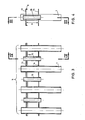
- FIG. 4 is the section IV-IV of Fig. 3
- Fig. 5 and 6 in view from the left show the tubular batteries of Fig. 1 and 3 concreted in the concrete floor of a filter field.
- the pipe nozzles 1 (FIG. 1), all of the same length and the same diameter in the first exemplary embodiment, are intended for the removal of the filtrate from and the supply of the flushing media to the drainage pipes 2 (FIG. 5), the filter nozzles 10 (Fig. 5) wear; the pipe sockets 1 therefore open into a collecting duct 6 (FIG. 5) lying under the concrete floor of the filter field.
- the pipe socket 1 are lined up at a predetermined distance with a vertical axis and are fixed relative to one another by a closed upper web 3 and a closed lower web 4.
- the connection of the pipe socket 1 to the web 3 and 4 is advantageously carried out by welding or gluing.
- the webs 1 and 4 which combine the pipe sockets 1 to form a tubular battery 5 in turn have a vertical distance a which, as shown in FIG. 5, corresponds to the thickness of the concrete floor to be concreted.
- the width of the webs 3 and 4 of the first embodiment corresponds, as shown in FIGS. 2 and 5, to the width of the collecting duct 6.
- the webs 3 and 4 therefore form a lost formwork with which the ceiling 7 of the collecting duct which forms part of the concrete floor 6 can be manufactured without additional formwork elements.
- the upper web 3 is folded in the longitudinal direction so that there is a widened edge 8 of a few centimeters, for example 2-4 cm in height.
- This edge 8 makes it much easier to produce the smooth line 9 (FIG. 5) which closes off the filter bottom, since the smooth line 9 only has to be brought up to this straight edge.
- the tubular battery 5 according to FIGS. 3 and 4 differs from the first embodiment on the one hand in that its long, wide pipe socket 1 alternates with short, narrow pipe socket 5, on which - which is not expressly shown - drainage pipes with a smaller diameter are also inserted .
- the pipe sockets 1 and 15 and thus the drainage pipes connected to them are fed with different backwashing media in two-phase backwashing.
- the webs 13 and 14 are made relatively narrow, which facilitates the handling and transport of the tubular batteries 5.
- the filter base 12 and the ceiling 17 of the collecting duct can therefore be cast in one or two work steps, wherein for the concreting of the ceiling 17 in the collecting duct 6, a formwork, not shown, is attached, on which the web 14 during the concreting of the ceiling 17th is fixed.
- the backfilling of the folded edge on the upper web 3 or 13 is ensured in both cases, for example, by vibration compaction when concreting the floor 12 or the ceiling 7 or 17.
Landscapes
- Chemical & Material Sciences (AREA)
- Chemical Kinetics & Catalysis (AREA)
- Filtration Of Liquid (AREA)
- Forms Removed On Construction Sites Or Auxiliary Members Thereof (AREA)
Applications Claiming Priority (2)
| Application Number | Priority Date | Filing Date | Title |
|---|---|---|---|
| CH5220/82A CH661954A5 (de) | 1982-09-02 | 1982-09-02 | Vorrichtung zur fixierung von drainagerohren. |
| CH5220/82 | 1982-09-02 |
Publications (3)
| Publication Number | Publication Date |
|---|---|
| EP0104263A2 true EP0104263A2 (fr) | 1984-04-04 |
| EP0104263A3 EP0104263A3 (en) | 1986-06-11 |
| EP0104263B1 EP0104263B1 (fr) | 1988-02-10 |
Family
ID=4289954
Family Applications (1)
| Application Number | Title | Priority Date | Filing Date |
|---|---|---|---|
| EP82108799A Expired EP0104263B1 (fr) | 1982-09-02 | 1982-09-23 | Dispositif pour la fixation de tuyaux de drainage |
Country Status (4)
| Country | Link |
|---|---|
| EP (1) | EP0104263B1 (fr) |
| CH (1) | CH661954A5 (fr) |
| DE (1) | DE3278103D1 (fr) |
| ES (1) | ES8405868A1 (fr) |
Family Cites Families (7)
| Publication number | Priority date | Publication date | Assignee | Title |
|---|---|---|---|---|
| FR835315A (fr) * | 1937-03-17 | 1938-12-19 | Fr De L Epuration Des Eaux Soc | Filtres pour liquides |
| US2401121A (en) * | 1944-12-11 | 1946-05-28 | Builders Iron Foundry | Means for constructing filter bottoms |
| US2648439A (en) * | 1950-11-01 | 1953-08-11 | Permutit Co | Filter bottom |
| US4159099A (en) * | 1977-05-09 | 1979-06-26 | Maguire James V | Sleeve assembly for forming openings in molded structures |
| DE2847076A1 (de) * | 1978-10-28 | 1980-05-08 | Metallgesellschaft Ag | Filteranlage |
| CH639864A5 (de) * | 1979-05-31 | 1983-12-15 | Sulzer Ag | Rueckspuelbare filteranlage zum reinigen von wasser. |
| CH636399A5 (de) * | 1979-05-31 | 1983-05-31 | Sulzer Ag | Vorrichtung zum voruebergehenden fixieren von verbindungselementen fuer drainagerohre waehrend des einbetonierens in den boden eines filterfeldes. |
-
1982
- 1982-09-02 CH CH5220/82A patent/CH661954A5/de not_active IP Right Cessation
- 1982-09-23 EP EP82108799A patent/EP0104263B1/fr not_active Expired
- 1982-09-23 DE DE8282108799T patent/DE3278103D1/de not_active Expired
-
1983
- 1983-07-16 ES ES524191A patent/ES8405868A1/es not_active Expired
Also Published As
| Publication number | Publication date |
|---|---|
| ES524191A0 (es) | 1984-06-16 |
| EP0104263B1 (fr) | 1988-02-10 |
| ES8405868A1 (es) | 1984-06-16 |
| CH661954A5 (de) | 1987-08-31 |
| EP0104263A3 (en) | 1986-06-11 |
| DE3278103D1 (en) | 1988-03-17 |
Similar Documents
| Publication | Publication Date | Title |
|---|---|---|
| DE2811772C2 (de) | Drainagerohr | |
| DE2406862C2 (de) | Gelenkig zusammenlegbares Bauwerk | |
| EP1801506A1 (fr) | Ensemble en cascade pour installation de chauffage avec deux chaudières ou plus | |
| DE2725742C2 (de) | Aus plattenförmigen Deckenelementen aufgebaute Decke | |
| DE9106070U1 (de) | Schalung | |
| DE1609137B1 (de) | Oberflaechen- bzw.Abwassersammelschacht | |
| EP0104263B1 (fr) | Dispositif pour la fixation de tuyaux de drainage | |
| WO2005040525A1 (fr) | Systeme de coffrage | |
| DE2252589A1 (de) | Kanalsystem zur verteilung klimatisierter luft | |
| EP0161634A2 (fr) | Poussard en particulier applicable aux travaux de blindage, p.e. blindage de tranchée | |
| CH636399A5 (de) | Vorrichtung zum voruebergehenden fixieren von verbindungselementen fuer drainagerohre waehrend des einbetonierens in den boden eines filterfeldes. | |
| DE1659218C3 (de) | Verbundfachwerkträger sowie Verfahren zu dessen Montage | |
| DE1534435A1 (de) | Zerlegbares Tragwerk fuer zerlegbare Bruecken od.dgl. | |
| DE2158920A1 (de) | Vorrichtung zur Dampftrocknung und -überhitzung | |
| EP0052761A2 (fr) | Dispositif pour serrer des éléments de coffrage | |
| DE3015151C2 (de) | Ausbau für eine Streckengabelung | |
| DE3302821A1 (de) | Betonschalung | |
| DE1938238B2 (de) | Baueinheit | |
| DE112018001604T5 (de) | Dampfturbinenanlage | |
| DE3871960T2 (de) | Bodenstruktur fuer gebaeude. | |
| DE3234355C1 (de) | Stützvorrichtung für ein Siebband | |
| DE1634148C (de) | Verfahren zum Bauen von Trogbrucken für Kanaluberfuhrungen und Trogbrucke zum Durchfuhren dieses Verfahrens | |
| WO2024042558A1 (fr) | Coffrage de puits | |
| DE1534872C3 (de) | Innenschalung für raumgroße Betonbauwerke | |
| DE1781262C (de) | Selbsttragender, mindestens zweifach abgestutzter Blechkanal |
Legal Events
| Date | Code | Title | Description |
|---|---|---|---|
| PUAI | Public reference made under article 153(3) epc to a published international application that has entered the european phase |
Free format text: ORIGINAL CODE: 0009012 |
|
| AK | Designated contracting states |
Designated state(s): AT BE CH DE FR GB IT LI LU NL SE |
|
| PUAL | Search report despatched |
Free format text: ORIGINAL CODE: 0009013 |
|
| AK | Designated contracting states |
Kind code of ref document: A3 Designated state(s): AT BE CH DE FR GB IT LI LU NL SE |
|
| 17P | Request for examination filed |
Effective date: 19860917 |
|
| RBV | Designated contracting states (corrected) |
Designated state(s): DE FR GB IT |
|
| 17Q | First examination report despatched |
Effective date: 19870603 |
|
| ITF | It: translation for a ep patent filed | ||
| GRAA | (expected) grant |
Free format text: ORIGINAL CODE: 0009210 |
|
| AK | Designated contracting states |
Kind code of ref document: B1 Designated state(s): DE FR GB IT |
|
| REF | Corresponds to: |
Ref document number: 3278103 Country of ref document: DE Date of ref document: 19880317 |
|
| GBT | Gb: translation of ep patent filed (gb section 77(6)(a)/1977) | ||
| ET | Fr: translation filed | ||
| PLBE | No opposition filed within time limit |
Free format text: ORIGINAL CODE: 0009261 |
|
| STAA | Information on the status of an ep patent application or granted ep patent |
Free format text: STATUS: NO OPPOSITION FILED WITHIN TIME LIMIT |
|
| 26N | No opposition filed | ||
| ITTA | It: last paid annual fee | ||
| PGFP | Annual fee paid to national office [announced via postgrant information from national office to epo] |
Ref country code: FR Payment date: 19920909 Year of fee payment: 11 |
|
| PG25 | Lapsed in a contracting state [announced via postgrant information from national office to epo] |
Ref country code: FR Free format text: LAPSE BECAUSE OF NON-PAYMENT OF DUE FEES Effective date: 19940531 |
|
| REG | Reference to a national code |
Ref country code: FR Ref legal event code: ST |
|
| PGFP | Annual fee paid to national office [announced via postgrant information from national office to epo] |
Ref country code: GB Payment date: 20010814 Year of fee payment: 20 |
|
| PGFP | Annual fee paid to national office [announced via postgrant information from national office to epo] |
Ref country code: DE Payment date: 20010903 Year of fee payment: 20 |
|
| REG | Reference to a national code |
Ref country code: GB Ref legal event code: IF02 |
|
| PG25 | Lapsed in a contracting state [announced via postgrant information from national office to epo] |
Ref country code: GB Free format text: LAPSE BECAUSE OF EXPIRATION OF PROTECTION Effective date: 20020922 |
|
| REG | Reference to a national code |
Ref country code: GB Ref legal event code: PE20 Effective date: 20020922 |