EP0104302B1 - Dispositif pour la fixation d'outil - Google Patents
Dispositif pour la fixation d'outil Download PDFInfo
- Publication number
- EP0104302B1 EP0104302B1 EP83100654A EP83100654A EP0104302B1 EP 0104302 B1 EP0104302 B1 EP 0104302B1 EP 83100654 A EP83100654 A EP 83100654A EP 83100654 A EP83100654 A EP 83100654A EP 0104302 B1 EP0104302 B1 EP 0104302B1
- Authority
- EP
- European Patent Office
- Prior art keywords
- frame component
- component
- retaining
- pad
- components
- Prior art date
- Legal status (The legal status is an assumption and is not a legal conclusion. Google has not performed a legal analysis and makes no representation as to the accuracy of the status listed.)
- Expired
Links
- 238000000034 method Methods 0.000 claims description 12
- 230000008878 coupling Effects 0.000 description 14
- 238000010168 coupling process Methods 0.000 description 14
- 238000005859 coupling reaction Methods 0.000 description 14
- 230000002411 adverse Effects 0.000 description 4
- 230000015556 catabolic process Effects 0.000 description 1
- 230000006835 compression Effects 0.000 description 1
- 238000007906 compression Methods 0.000 description 1
- 230000000694 effects Effects 0.000 description 1
- 238000012986 modification Methods 0.000 description 1
- 230000004048 modification Effects 0.000 description 1
- 230000008439 repair process Effects 0.000 description 1
- 230000000284 resting effect Effects 0.000 description 1
Images




Classifications
-
- E—FIXED CONSTRUCTIONS
- E02—HYDRAULIC ENGINEERING; FOUNDATIONS; SOIL SHIFTING
- E02F—DREDGING; SOIL-SHIFTING
- E02F3/00—Dredgers; Soil-shifting machines
- E02F3/04—Dredgers; Soil-shifting machines mechanically-driven
- E02F3/28—Dredgers; Soil-shifting machines mechanically-driven with digging tools mounted on a dipper- or bucket-arm, i.e. there is either one arm or a pair of arms, e.g. dippers, buckets
- E02F3/36—Component parts
- E02F3/3604—Devices to connect tools to arms, booms or the like
- E02F3/3609—Devices to connect tools to arms, booms or the like of the quick acting type, e.g. controlled from the operator seat
-
- E—FIXED CONSTRUCTIONS
- E01—CONSTRUCTION OF ROADS, RAILWAYS, OR BRIDGES
- E01H—STREET CLEANING; CLEANING OF PERMANENT WAYS; CLEANING BEACHES; DISPERSING OR PREVENTING FOG IN GENERAL CLEANING STREET OR RAILWAY FURNITURE OR TUNNEL WALLS
- E01H4/00—Working on surfaces of snow or ice in order to make them suitable for traffic or sporting purposes, e.g. by compacting snow
- E01H4/02—Working on surfaces of snow or ice in order to make them suitable for traffic or sporting purposes, e.g. by compacting snow for sporting purposes, e.g. preparation of ski trails; Construction of artificial surfacings for snow or ice sports ; Trails specially adapted for on-the-snow vehicles, e.g. devices adapted for ski-trails
-
- E—FIXED CONSTRUCTIONS
- E01—CONSTRUCTION OF ROADS, RAILWAYS, OR BRIDGES
- E01H—STREET CLEANING; CLEANING OF PERMANENT WAYS; CLEANING BEACHES; DISPERSING OR PREVENTING FOG IN GENERAL CLEANING STREET OR RAILWAY FURNITURE OR TUNNEL WALLS
- E01H5/00—Removing snow or ice from roads or like surfaces; Grading or roughening snow or ice
- E01H5/04—Apparatus propelled by animal or engine power; Apparatus propelled by hand with driven dislodging or conveying levelling elements, conveying pneumatically for the dislodged material
- E01H5/06—Apparatus propelled by animal or engine power; Apparatus propelled by hand with driven dislodging or conveying levelling elements, conveying pneumatically for the dislodged material dislodging essentially by non-driven elements, e.g. scraper blades, snow-plough blades, scoop blades
Definitions
- the present invention relates in general to a method and to a device of the type employed to mount and dismount heavy duty tool components on vehicles according to the first parts of claims 1 and 4.
- the present invention is particularly adapted for, although not strictly limited in use to, the mounting of snow ploughs, scrapers, compactors etc. on track-propelled vehicles of the type used for establishing and maintaining ski trails.
- Such vehicles and their tool components are normally operated at high elevations on steep and varyingly sloped and undulating terrain often under extremely adverse weather conditions, thus subjecting the tool mounting arrangements to heavy use accompanied by high stresses.
- the mounting arrangements must therefore be rugged and wear resistant, otherwise they will be subject to frequent breakdowns at locations where repairs are difficult, if not impossible, to carry out.
- the FR-A-15 03 496 discloses a method and a device of the afore-mentioned species designed to facilitate the interchange of one tool component for another.
- a relatively large clearance is provided in both the horizontal and vertical direction between the connection means consisting of an eyelet and a coupling jaw, both projecting according to the embodiment shown in Fig. 2, vertically from the upper portion of the tool component and the top part of the frame component, respectively, as well as a coupling pin slidably mounted within the coupling jaw and adapted to slide into the eyelet as soon as same is received within the coupling jaw.
- the connection means a resiliently compressible pad extending vertically on the frame component and a corresponding contact surface extending vertically on the tool component.
- the retaining means consisting of one bracket each on both components, each bracket having a through-hole and a bolt adapted to be slid through the two through-holes thus retaining the frame component onto the tool component.
- the two components and their compressible pads and corresponding contact surfaces are horizontally spaced from each other by the time the eyelet is received within the coupling jaw and both are locked by means of coupling pin.
- at least one of the resiliently compressible pad is moved into pressure engagement with the corresponding contact surface so as to compensate the clearance and possible wear between the connection means.
- the closing of this gap although not very large, is rather costly as it not only needs an appropriate means for moving the pad into pressure engagement and back, but it also has to be carried out manually, either through an attendant or through the driver of the vehicle, which, in both cases, is time consuming. Further, the attendant or the driver are required to engage the retaining means with each other by manually moving the lower portion of the tool component against the frame component until the two through-holes are aligned with each other and by sliding the bolt into bolt through-holes.
- the compressible pads and the corresponding contact surfaces are arranged below and above the eyelet and the coupling jaw both projecting horizontally from the middle portion of the two components. From that it follows that the two components can only be connected in those cases in which they are facing each other in approximately parallel planes, namely on straight ground. On adverse terrain, particularly on such where the ground in front of the frame component and supporting the tool component changes its slope upwardly or downwardly relative to the ground supporting the frame component so as to be undulating, the two components are inclined relatively to each other so that their coupling together is almost impossible. Of course, the gap that exists between the two components before the connection means are locked with each other is somewhat accommodating in this respect.
- the problem is solved by lifting the tool component relative to the frame component into a locked position through tilting the frame component being engaged by way of the connection means with the tool component about a generally horizontal axis into an inclined position in which the pad means and the contact means as well as the retaining means are in substantially vertical alignment with, but spaced from, each other and through moving the connection means provided on the frame component in a generally upward direction relative to the frame component, into its locked position with a connection means provided on the tool component, resulting in the retaining means provided on the tool component entering into retaining engagement with the retaining means provided on the frame component with accompanying compressive engagement of the contact means against the resiliently compressible pad means.
- connection means provided on the frame component is mounted thereon so as to be vertically adjustable relative to the frame component from an unlocked position into a locked position with the connection means provided on the tool component, in that an operating means is provided on the frame component for vertically adjusting the connecting means provided on the frame component from the unlocked position into the locked position with the connection means provided on the tool component, in that a second ram means is provided for adjusting the frame component angularly about a generally horizontal axis connecting the link means with the frame component, in that the retaining means provided on one of the two components is designed as a slot means open at its end facing towards the retaining means provided on the other of the two components to allow the latter retaining means to enter into retaining engagement with the slot means upon lifting of the tool component relative to the frame component, and in that the pad means and the contact means are each mounted fixedly on the respc- tive components on a generally horizontal plane, both planes being vertically spaced from each other, so as to attain compressive biasing of the
- a device of straightforward design which permits the two components to be connected and disconnected in an extremely rapid fashion, since the tool component is lifted without any manual attendance in one smooth movement directly into a locked position with the frame component, in which position the connection means and the pad means or the contact means provided on the tool component (and thus the latter itself) are engaged with their counterparts provided on the frame component.
- the resiliently compressible pad means is held by the connection means provided on the frame component in pressure engagement with the contact means so as to compensate for clearance and wear between the connection means and, in turn to ensure a secure and rattle-free connection.
- the retaining means are provided to take any forces acting in a generally horizontal direction which may overcome compression forces between the contact means and the pad means and thus disengage both from each other.
- the pad means, and the contact means and the retaining means are being pulled upwardly into pressure engagement, they have to be initially, that is before being pulled, spaced from each other in a vertical direction such that they do not engage with each other.
- the two components are initially in contact with each other only through the connection means so that the tool component, even when standing with a relative large inclination relative to the frame component on undulating ground, is in conjunction with the tilting movement of the frame component capable of being connected with the frame component without any obstruction through a second area of contact.
- US-A-4236329 discloses a method and a device for detachably connecting a tool component, e.g. a snow plough, to a vehicle by means of an adjustable frame component.
- a tool component e.g. a snow plough
- this method and device are not of the same species as the inventive method and device and are not within the scope the average man skilled in the art considers when being faced with the problem underlying the invention.
- the two components of this known device are provided with upper and lower connection means, between which the tool component is clamped.
- the upper and lower connection means provided on the frame component are mounted at the respective ends of an over-centre toggle linkage that is adapted to be actuated such that the upper connection means is moved upwards and the lower connection means is moved downwards.
- the upper connection means provided on the frame component engages its counterpart provided on the tool component whereby the tool component is being lifted simultaneously with the lower connection means provided on the frame component being lowered until it comes into engagement with its counterpart provided on the tool component.
- the toggle linkage is further actuated such that upon reaching their highest position, the upper connection means provided on the frame component and therewith the tool component are lowered into an over-centre locked position.
- this locked position there is clearance within the upper and the lower connection means provided on both components, said clearance permitting rattling movements of the tool component whereby the wear occurring therewith increases the clearance within the connection means and, thus, the rattling movements.
- a tool component in the form of a snow plow blade 10 is shown detachably mounted to the front end of a track-propelled vehicle 12 by means of a tool mounting apparatus generally indicated at 14.
- the tool mounting apparatus includes a "frame component" 16 consisting essentially of front and rear horizontal box beams 16a, 16b which are pivotally joined together at 17, and which respectively support somewhat triangularly shaped vertically upstanding front and rear plates 16c and 16d.
- the front and rear plates 16c, 16d are spaced apart at their upper ends by intermediate components 16e, which in turn underlie a cap piece 16f extending rearwardly from the front plate 16c.
- the front beam 16a and its respective component is pivoted about connection 17 relative to the rear beam 16b by means of a piston-cylinder unit 15.
- the frame component 16 is connected to the front end of the vehicle 12 by an intermediate “link means" generally indicated at 18, the latter being pivotally connected to the rear side of the box beam 16b as at 20 and to the front end of the vehicle as at 22.
- the pivotal connection 20 establishes a horizontal axis about which the frame component 16 may be inclined, as will be described hereinafter in more detail.
- Bracketaining means consisting of a slot means 26 and a pin means 28 are provided.
- brackets 24 are secured in a laterally spaced relationship to the front face of the box beam 16a.
- the brackets 24 are slotted as at 26 to provide the "slot means” adapted to interengage with the "pin means” consisting of pin members 28 extending laterally between brackets 30 secured to the back side of the snow plow 10.
- a pair of locking arms 32 are fixedly interconnected by a sleeve 34 which is in turn rotatably mounted on an axle 36 establishing another horizontal axis parallel to the previously mentioned axis established by pivots 20.
- the axle 36 is supported between brackets 38 extending forwardly from the cap piece 16f.
- the arms 32 are notched as at 40 to provide a "notch means” adapted to interengage with an "engagement means” in the form of a horizontal bar 42, the latter being supported between brackets 44 on the rear side of the plow blade 10, as is best shown in Figure 2.
- An “operating means” includes a crank arm 46 extending laterally from the sleeve 34.
- the crank arm 46 is pivotally connected as at 48 to the piston rod 49 of a linear actuator in the form of a hydraulic ram 50.
- the ram cylinder is pivotally connected as at 52 to brackets 54 supported on the front box beam 16a of the frame component 16.
- Extension and retraction of the piston rod 49 of ram 50 will result in the locking arms 32 being adjusted between an unlocked position at which the notches 40 open in a forward direction transverse to the downwardly open direction of the notches 26 of the lower brackets 24, and a locked position at which their notches 40 open in an upward direction generally opposite to that of the downwardly open notches 26 as shown for example in Figures 6 and 7.
- a pair of resiliently compressible pads 56 is located on the front side of the box beam 16a. These pads, which can conveniently comprise commercially available rubber bumpers, are secured to mounting plates 58 welded to the top of the box beam 16a.
- the pads 56 are removably attached to their respective plates by any convenient means such as for example the bolts 60 shown in Figure 8, thus facilitating their replacement after normal wear has taken place.
- the compressible pads 56 are adapted to be compressively engaged by "contact means" in the form of shelf-like plates 62 which protrude rearwardly from the snow plow blade 10.
- a pair of vertically protruding plates 64 are mounted on the top of the frame cap 16f.
- the plates 64 are notched as at 66 and as such define "additional notch means”.
- Hydraulic rams 68 and 70 operate in conjunction with the movement of the vehicle 12 to adjust the position of the frame component 16.
- the hydraulic ram 68 is pivotally connected to the frame component 16 as at 72 and to the vehicle at 74.
- the hydraulic ram 70 is pivotally connected to the link means 18 as at 76 and to the vehicle as at 78.
- the frame component 16 When attaching a tool component such as the snow plow blade 10 to the vehicle, the frame component 16 is first brought to a "first or starting position" as shown in Figure 3. This is accomplished by moving the vehicle 12 to a desired location and by adjusting the elevation of the frame component through appropriate operation of the rams 68, 70. At this "first or starting position", the locking arms 32 have been rotated to their unlocked position, with their notches 40 facing the horizontal bar 42 on the plow blade. The lower horizontal edges of the notches 40 extend forwardly of the frame component and are spaced below the level of bar 42. Any inclination of the plow blade and its bar 42 can be compensated for by operating the piston-cylinder unit 15 to incline the front beam 16a and its associated components to an appropriate angle.
- the vehicle 12 is then advanced towards the blade 10 to a point where the horizontal bar 42 is received in the notches 40 of the locking arms 32.
- the hydraulic rams 68, 70 are operated to elevate the frame component to a "second or elevated position" as shown in Figure 4.
- the plow blade 10 is suspended from the frame component 16 by virtue of the interengagement of the horizontal bar 42 within the notches of the locking arms 32.
- the lower pin members 28 are spaced forwardly of the notched brackets 24, and the contact plates 62 are similarly spaced forwardly of the compressible pads 56.
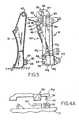
- the hydraulic ram 68 is next operated to rearwardly incline the frame component 16 about the horizontal axis defined by pivot points 20 to a "third or inclined position" as shown in Figure 5. This has the effect of swinging the lower portion of the plow blade towards the lower portion of the frame component until the lower pin members 28 rest against the bracket 24, thus aligning the pin members with the notches 26.
- the contact plates 62 also are aligned with but spaced below the compressible pads 56.
- the hydraulic ram 50 is then operated to rotate the locking arms 32 to the locked position shown in Figure 6.
- the interengagement of the horizontal bar 42 and the surfaces of the notches 40 causes the blade 10 to move upwardly in relation to the frame component 16 until the bar 42 is securely confined within the notches 40 and 66 between the locking arms 32 and the vertically protruding top plates 64.
- the lower pin members 28 are being pulled up into the notches 26 and the contact plates 62 are being drawn into compressible engagement with the pads 56.
- the rams 50, 68, 70 are all controllable by known means (not shown) from the vehicle cab.
- the vehicle operator can perform the entire mounting sequence without leaving the vehicle cab and without having to manually engage component parts.
- the above sequence is simply reversed.
Landscapes
- Engineering & Computer Science (AREA)
- Civil Engineering (AREA)
- Structural Engineering (AREA)
- Architecture (AREA)
- Mechanical Engineering (AREA)
- General Engineering & Computer Science (AREA)
- Mining & Mineral Resources (AREA)
- Cleaning Of Streets, Tracks, Or Beaches (AREA)
- Shovels (AREA)
- Connection Of Plates (AREA)
- Die Bonding (AREA)
- Constituent Portions Of Griding Lathes, Driving, Sensing And Control (AREA)
- Vehicle Cleaning, Maintenance, Repair, Refitting, And Outriggers (AREA)
- Lock And Its Accessories (AREA)
Claims (18)
Priority Applications (1)
| Application Number | Priority Date | Filing Date | Title |
|---|---|---|---|
| AT83100654T ATE30385T1 (de) | 1982-09-29 | 1983-01-25 | Befestigungseinrichtung fuer ein geraet. |
Applications Claiming Priority (2)
| Application Number | Priority Date | Filing Date | Title |
|---|---|---|---|
| US06/428,107 US4462172A (en) | 1982-09-29 | 1982-09-29 | Quick disconnect blade tool mounting apparatus |
| US428107 | 1982-09-29 |
Publications (2)
| Publication Number | Publication Date |
|---|---|
| EP0104302A1 EP0104302A1 (fr) | 1984-04-04 |
| EP0104302B1 true EP0104302B1 (fr) | 1987-10-28 |
Family
ID=23697582
Family Applications (1)
| Application Number | Title | Priority Date | Filing Date |
|---|---|---|---|
| EP83100654A Expired EP0104302B1 (fr) | 1982-09-29 | 1983-01-25 | Dispositif pour la fixation d'outil |
Country Status (6)
| Country | Link |
|---|---|
| US (1) | US4462172A (fr) |
| EP (1) | EP0104302B1 (fr) |
| JP (1) | JPS5985039A (fr) |
| AT (1) | ATE30385T1 (fr) |
| CA (1) | CA1182638A (fr) |
| DE (2) | DE104302T1 (fr) |
Cited By (1)
| Publication number | Priority date | Publication date | Assignee | Title |
|---|---|---|---|---|
| DE19647176C1 (de) * | 1996-11-14 | 1998-07-16 | Beilhack Systemtechnik Und Ver | Schneepflug |
Families Citing this family (30)
| Publication number | Priority date | Publication date | Assignee | Title |
|---|---|---|---|---|
| US4761113A (en) * | 1986-06-20 | 1988-08-02 | J. I. Case Company | Quick coupler assembly |
| JPH0414517Y2 (fr) * | 1988-09-13 | 1992-03-31 | ||
| DE3932944A1 (de) * | 1988-10-06 | 1990-04-12 | Schmidt Alfred Ing Gmbh | Vorrichtung zum anbau eines schneepfluges an ein fahrzeug |
| US5031927A (en) * | 1989-07-14 | 1991-07-16 | Frenette Albert E | Semi-automatic attach device for mounting snowplows |
| US4967850A (en) * | 1989-11-02 | 1990-11-06 | Caterpillar Inc. | Combined tooth retractor and blade latching mechanism |
| US4962599A (en) * | 1990-04-12 | 1990-10-16 | Dsp, Inc. | Quick connect-disconnect coupling for snow plow |
| CA2024409C (fr) * | 1990-08-31 | 1993-03-02 | Andre Aubichon | Accessoire pour l'enlevement de la neige |
| DE29500818U1 (de) * | 1995-01-19 | 1995-03-02 | Kässbohrer Geländefahrzeug GmbH, 89077 Ulm | Pistenpflegegerät |
| GB9520448D0 (en) * | 1995-10-06 | 1995-12-06 | Mccann Noel P M | Excavator hitch |
| US5669450A (en) * | 1995-12-20 | 1997-09-23 | Martin Equipment Of Illinois, Inc. | Quick mount front end scarifier |
| US5713418A (en) * | 1996-07-18 | 1998-02-03 | Warren Power Attachments | Vibratory compactor |
| US6209231B1 (en) | 1998-08-14 | 2001-04-03 | Curtis International, Inc. | Vehicle hitch mount assembly for a snow plow |
| US6145222A (en) | 1998-08-14 | 2000-11-14 | Curtis International, Inc. | Vehicle hitch mount assembly for a snow plow |
| JP4097829B2 (ja) * | 1999-02-24 | 2008-06-11 | 本田技研工業株式会社 | 除雪機 |
| US6363629B1 (en) | 2000-02-18 | 2002-04-02 | Curtis International, Inc. | Vehicle hitch mount assembly for a snow plow |
| US6526677B1 (en) * | 2000-10-06 | 2003-03-04 | Douglas Dynamics, L.L.C. | Snowplow mounting assembly |
| US7114270B2 (en) * | 2003-01-24 | 2006-10-03 | The Louis Berkman Company | Plow mounting apparatus and method |
| US20060055150A1 (en) * | 2003-09-29 | 2006-03-16 | Ltt Biio-Phara Co., Ltd | Vehicle mount assembly for a utilitarian accessory |
| US7565756B2 (en) * | 2006-03-03 | 2009-07-28 | Parker-Hannifin Corporation | Lost motion mechanism for movable vehicle implements |
| US8393096B2 (en) * | 2008-02-28 | 2013-03-12 | Charles A. Thomas | Plow for use with a motorized wheelchair |
| US7866935B1 (en) * | 2008-12-11 | 2011-01-11 | TAG Manufacturing, Inc. | Manually operated coupler |
| DE102009019865A1 (de) * | 2009-05-06 | 2010-11-18 | Rheinmetall Landsysteme Gmbh | Rad- oder Kettenfahrzeug mit einer an dem Fahrzeug angeordneten Räum- und/oder Stützanlage |
| JP5616848B2 (ja) * | 2011-06-01 | 2014-10-29 | 株式会社クボタ | ブレード装置 |
| DE102014200899A1 (de) | 2013-12-20 | 2015-06-25 | Kässbohrer Geländefahrzeug AG | Pistenraupe und Räumschild für eine derartige Pistenraupe |
| US10731318B2 (en) | 2017-02-20 | 2020-08-04 | Cnh Industrial America Llc | System and method for coupling an implement to a work vehicle |
| US11041284B2 (en) * | 2017-02-20 | 2021-06-22 | Cnh Industrial America Llc | System and method for coupling an implement to a work vehicle |
| US10294629B1 (en) * | 2018-05-16 | 2019-05-21 | Deere & Company | Holder for coupling a work implement to a work vehicle |
| US11613871B2 (en) | 2019-05-02 | 2023-03-28 | Cnh Industrial America Llc | Systems and methods for coupling an implement to a work vehicle |
| US11920322B2 (en) | 2019-05-02 | 2024-03-05 | Cnh Industrial America Llc | Systems and methods for coupling an implement to a work vehicle |
| US11261579B1 (en) | 2021-08-30 | 2022-03-01 | Homer Willis | Bucket mountable plow |
Family Cites Families (15)
| Publication number | Priority date | Publication date | Assignee | Title |
|---|---|---|---|---|
| US3312004A (en) * | 1964-06-01 | 1967-04-04 | Thys Company | Ripper tooth assembly |
| AT274037B (de) * | 1965-12-14 | 1969-09-10 | Gottfried Dr Reissinger | Vorrichtung zum Anbringen eines Gerätes, insbesondere eines Schneeräumgerätes an einem Fahrzeug |
| BE791834A (nl) * | 1971-12-01 | 1973-03-16 | Verachtert Antonius P | Graafmachine |
| US3952431A (en) * | 1974-10-21 | 1976-04-27 | Gledhill Road Machinery Company | Vehicular carried plow coupling |
| US3985249A (en) * | 1975-04-14 | 1976-10-12 | International Harvester Company | Quick change attachment |
| JPS5294601A (en) * | 1976-02-03 | 1977-08-09 | Caterpillar Mitsubishi Ltd | Quick coupler |
| JPS52101801A (en) * | 1976-02-24 | 1977-08-26 | Caterpillar Mitsubishi Ltd | Quick coupler |
| US4201000A (en) * | 1977-09-06 | 1980-05-06 | Stanford George H | Snow plow attachment |
| US4136792A (en) * | 1977-11-07 | 1979-01-30 | J. I. Case Company | Quick attachment device for a lifting tractor |
| US4187050A (en) * | 1978-02-15 | 1980-02-05 | Caterpillar Tractor Co. | Quick-disconnect mechanical coupling |
| JPS5820343B2 (ja) * | 1978-03-30 | 1983-04-22 | キヤタピラ−三菱株式会社 | クイツクカブラ |
| US4311428A (en) * | 1979-05-16 | 1982-01-19 | Wain-Roy, Inc. | Connectors |
| US4236329A (en) * | 1979-07-12 | 1980-12-02 | Meyer Products, Inc. | Detachable blade mounting device |
| US4355945A (en) * | 1979-12-03 | 1982-10-26 | Ware Machine Service, Inc. | Tool mounting apparatus |
| US4297074A (en) * | 1980-01-07 | 1981-10-27 | Ballinger Paul V | Demountable interconnection |
-
1982
- 1982-09-29 US US06/428,107 patent/US4462172A/en not_active Expired - Lifetime
-
1983
- 1983-01-25 DE DE198383100654T patent/DE104302T1/de active Pending
- 1983-01-25 EP EP83100654A patent/EP0104302B1/fr not_active Expired
- 1983-01-25 AT AT83100654T patent/ATE30385T1/de not_active IP Right Cessation
- 1983-01-25 DE DE8383100654T patent/DE3374175D1/de not_active Expired
- 1983-03-30 CA CA000424881A patent/CA1182638A/fr not_active Expired
- 1983-09-29 JP JP58181740A patent/JPS5985039A/ja active Granted
Cited By (1)
| Publication number | Priority date | Publication date | Assignee | Title |
|---|---|---|---|---|
| DE19647176C1 (de) * | 1996-11-14 | 1998-07-16 | Beilhack Systemtechnik Und Ver | Schneepflug |
Also Published As
| Publication number | Publication date |
|---|---|
| JPH0363612B2 (fr) | 1991-10-01 |
| CA1182638A (fr) | 1985-02-19 |
| US4462172A (en) | 1984-07-31 |
| DE104302T1 (de) | 1984-07-19 |
| ATE30385T1 (de) | 1987-11-15 |
| JPS5985039A (ja) | 1984-05-16 |
| DE3374175D1 (en) | 1987-12-03 |
| EP0104302A1 (fr) | 1984-04-04 |
Similar Documents
| Publication | Publication Date | Title |
|---|---|---|
| EP0104302B1 (fr) | Dispositif pour la fixation d'outil | |
| US4657275A (en) | Self-aligning trailer hitch | |
| US5353530A (en) | Quick mounting snow plow assembly | |
| CA1194843A (fr) | Vehicule avec accessoire amovible | |
| US6928757B2 (en) | Snowplow mounting assembly | |
| US4236329A (en) | Detachable blade mounting device | |
| US4658519A (en) | Snowplow and implement attachment means for a vehicle | |
| US5125174A (en) | Removable snowflow with a pivotable lift stand | |
| US4264264A (en) | Loader mounting structure | |
| US6178669B1 (en) | Plow hitch assembly for vehicles | |
| US5967241A (en) | ATV lift handle | |
| US5286050A (en) | Hitch for trailers | |
| US5081775A (en) | Plow attaching device and method | |
| US4470613A (en) | Tractor hitches | |
| US5004398A (en) | Backhoe mounting device for a skid steer loader | |
| US5135347A (en) | Loader mounting | |
| US3746368A (en) | Vehicular carried plow coupling | |
| CA2279169C (fr) | Support stationnaire pour tractochargeur | |
| US6089818A (en) | Towing lift accessory | |
| US5263734A (en) | Coupling device for attaching towable implements to a tractor | |
| CA2580423A1 (fr) | Mecanisme a fixation rapide d'une lame a un vehicule tout terrain | |
| US4436162A (en) | Implement attachment for the front end of a tractor | |
| US4487269A (en) | Dozer blade angle adjustment mechanism | |
| US12497744B2 (en) | Containment plow | |
| FI75625B (fi) | Baeranordning foer framaendan av sidoplog. |
Legal Events
| Date | Code | Title | Description |
|---|---|---|---|
| PUAI | Public reference made under article 153(3) epc to a published international application that has entered the european phase |
Free format text: ORIGINAL CODE: 0009012 |
|
| AK | Designated contracting states |
Designated state(s): AT CH DE FR IT LI SE |
|
| ITCL | It: translation for ep claims filed |
Representative=s name: BARZANO' E ZANARDO ROMA S.P.A. |
|
| EL | Fr: translation of claims filed | ||
| TCAT | At: translation of patent claims filed | ||
| DET | De: translation of patent claims | ||
| 17P | Request for examination filed |
Effective date: 19840725 |
|
| ITF | It: translation for a ep patent filed | ||
| GRAA | (expected) grant |
Free format text: ORIGINAL CODE: 0009210 |
|
| AK | Designated contracting states |
Kind code of ref document: B1 Designated state(s): AT CH DE FR IT LI SE |
|
| REF | Corresponds to: |
Ref document number: 30385 Country of ref document: AT Date of ref document: 19871115 Kind code of ref document: T |
|
| REF | Corresponds to: |
Ref document number: 3374175 Country of ref document: DE Date of ref document: 19871203 |
|
| ET | Fr: translation filed | ||
| PG25 | Lapsed in a contracting state [announced via postgrant information from national office to epo] |
Ref country code: SE Effective date: 19880126 |
|
| PLBE | No opposition filed within time limit |
Free format text: ORIGINAL CODE: 0009261 |
|
| STAA | Information on the status of an ep patent application or granted ep patent |
Free format text: STATUS: NO OPPOSITION FILED WITHIN TIME LIMIT |
|
| 26N | No opposition filed | ||
| PG25 | Lapsed in a contracting state [announced via postgrant information from national office to epo] |
Ref country code: FR Effective date: 19890131 |
|
| ITTA | It: last paid annual fee | ||
| EUG | Se: european patent has lapsed |
Ref document number: 83100654.9 Effective date: 19880913 |
|
| REG | Reference to a national code |
Ref country code: FR Ref legal event code: ST |
|
| REG | Reference to a national code |
Ref country code: CH Ref legal event code: PUE Owner name: EVOBUS GMBH TRANSFER- KAESSBOHRER GELAENDEFAHRZEUG Ref country code: CH Ref legal event code: PFA Free format text: KARL KAESSBOHRER FAHRZEUGWERKE GMBH TRANSFER- EVOBUS GMBH |
|
| REG | Reference to a national code |
Ref country code: FR Ref legal event code: TP Ref country code: FR Ref legal event code: CD |
|
| PGFP | Annual fee paid to national office [announced via postgrant information from national office to epo] |
Ref country code: DE Payment date: 19980225 Year of fee payment: 16 |
|
| PG25 | Lapsed in a contracting state [announced via postgrant information from national office to epo] |
Ref country code: DE Free format text: LAPSE BECAUSE OF NON-PAYMENT OF DUE FEES Effective date: 19991103 |
|
| PGFP | Annual fee paid to national office [announced via postgrant information from national office to epo] |
Ref country code: AT Payment date: 20000120 Year of fee payment: 18 |
|
| PGFP | Annual fee paid to national office [announced via postgrant information from national office to epo] |
Ref country code: CH Payment date: 20000131 Year of fee payment: 18 |
|
| PG25 | Lapsed in a contracting state [announced via postgrant information from national office to epo] |
Ref country code: AT Free format text: LAPSE BECAUSE OF NON-PAYMENT OF DUE FEES Effective date: 20010125 |
|
| PG25 | Lapsed in a contracting state [announced via postgrant information from national office to epo] |
Ref country code: LI Free format text: LAPSE BECAUSE OF NON-PAYMENT OF DUE FEES Effective date: 20010131 Ref country code: CH Free format text: LAPSE BECAUSE OF NON-PAYMENT OF DUE FEES Effective date: 20010131 |
|
| REG | Reference to a national code |
Ref country code: CH Ref legal event code: PL |