EP0104307A2 - Large-surface rotating disc filter element in a tank - Google Patents
Large-surface rotating disc filter element in a tank Download PDFInfo
- Publication number
- EP0104307A2 EP0104307A2 EP83103639A EP83103639A EP0104307A2 EP 0104307 A2 EP0104307 A2 EP 0104307A2 EP 83103639 A EP83103639 A EP 83103639A EP 83103639 A EP83103639 A EP 83103639A EP 0104307 A2 EP0104307 A2 EP 0104307A2
- Authority
- EP
- European Patent Office
- Prior art keywords
- filter
- filter element
- boiler
- area
- beads
- Prior art date
- Legal status (The legal status is an assumption and is not a legal conclusion. Google has not performed a legal analysis and makes no representation as to the accuracy of the status listed.)
- Granted
Links
Images

Classifications
-
- B—PERFORMING OPERATIONS; TRANSPORTING
- B01—PHYSICAL OR CHEMICAL PROCESSES OR APPARATUS IN GENERAL
- B01D—SEPARATION
- B01D37/00—Processes of filtration
- B01D37/02—Precoating the filter medium; Addition of filter aids to the liquid being filtered
-
- B—PERFORMING OPERATIONS; TRANSPORTING
- B01—PHYSICAL OR CHEMICAL PROCESSES OR APPARATUS IN GENERAL
- B01D—SEPARATION
- B01D29/00—Filters with filtering elements stationary during filtration, e.g. pressure or suction filters, not covered by groups B01D24/00 - B01D27/00; Filtering elements therefor
- B01D29/39—Filters with filtering elements stationary during filtration, e.g. pressure or suction filters, not covered by groups B01D24/00 - B01D27/00; Filtering elements therefor with hollow discs side by side on, or around, one or more tubes, e.g. of the leaf type
- B01D29/41—Filters with filtering elements stationary during filtration, e.g. pressure or suction filters, not covered by groups B01D24/00 - B01D27/00; Filtering elements therefor with hollow discs side by side on, or around, one or more tubes, e.g. of the leaf type mounted transversely on the tube
- B01D29/416—Filtering tables
-
- B—PERFORMING OPERATIONS; TRANSPORTING
- B01—PHYSICAL OR CHEMICAL PROCESSES OR APPARATUS IN GENERAL
- B01D—SEPARATION
- B01D29/00—Filters with filtering elements stationary during filtration, e.g. pressure or suction filters, not covered by groups B01D24/00 - B01D27/00; Filtering elements therefor
- B01D29/62—Regenerating the filter material in the filter
- B01D29/70—Regenerating the filter material in the filter by forces created by movement of the filter element
- B01D29/74—Regenerating the filter material in the filter by forces created by movement of the filter element involving centrifugal force
-
- B—PERFORMING OPERATIONS; TRANSPORTING
- B01—PHYSICAL OR CHEMICAL PROCESSES OR APPARATUS IN GENERAL
- B01D—SEPARATION
- B01D33/00—Filters with filtering elements which move during the filtering operation
- B01D33/15—Filters with filtering elements which move during the filtering operation with rotary plane filtering surfaces
- B01D33/17—Filters with filtering elements which move during the filtering operation with rotary plane filtering surfaces with rotary filtering tables
Definitions
- the invention relates to a large-area rotary disk filter element for boiler filters with a hub,
- a circular base plate attached to it, a filter fabric stretched over it and a support fabric arranged between the base plate and the filter fabric.
- rotary disk filter elements are filter media in pressure-loaded boiler filters, such as in US Pat. No. 4,201,670 or in the DE-OS of the same name 27 05 046.
- the individual rotary disc filter elements are arranged on a central shaft and tightly clamped together. All rotary disc filter elements - together form a filter package.
- Rotating disc filter elements have the task of separating impurities from an unfiltrate and draining off the bare filtrate. The distance between the rotating disk filter elements is determined by the height of the hub.
- the separated filtration residues settle on the upper filter fabric of the rotating disc filter elements and form the filter cake.
- the filter cake grows and becomes thicker.
- the height of the total filter cake that builds up is determined by the distance between two rotary disc filter elements that are one above the other.
- the filter pack is set in rotation to remove the filter cake from the disc filter elements.
- the filter cake is removed from the rotating disk filter elements by the centrifugal force.
- the filter cake has a very considerable weight. It lies on the surface of each rotary disc filter element. So far, the rotations have been used so that the individual rotary disc filter elements cannot twist, bend or kink under the load of the filter cake disc filter elements with feet are supported on the rotating disc filter element underneath. These support feet are spaced evenly over the entire outer circumference of each rotary disc filter element.
- a disadvantage of this support is that the support feet cause a vortex formation in the area of each support foot when a basic deposit is applied to the filter fabric while the filter pack rotates slowly, so that washdowns occur in the vortex area or there is no basic deposit on the filter fabric at all.
- bad filtrate or g.ar unfiltrate penetrates into the filtrate and contaminates it.
- Only an even filter cake build-up guarantees from the beginning a constant effective free filter area over the entire duration of a filtration batch and thus a uniform hourly and total quantity output. Washed-off or bare spots quickly clog the tissue and thus reduce the free effective filter area.
- the support feet are namely the filter to be thrown off by centrifugal force cake in the way and prevent the cake pieces from sliding freely. More or less large sections are held by the feet. This creates an imbalance in the rotating filter package, which results in considerable damage to the machine and the building. In the case of filter cakes with a higher viscosity, it can even happen that the support feet are bent outwards or break off completely. It is not uncommon for the filter elements not to be 100% cleaned, despite the fact that they have been rotating for a long time, and that there are still cake residues in the area of the feet.
- the object of the present invention is to provide a large-area rotary disk filter element which, with simple means, ensures high stability with a better wash-up at the same time and trouble-free and flawless cleaning, as well as a rational method for operating such a rotary disk filter element.
- the stiffening is advantageously formed by beads which run essentially radially and coaxially to the central axis of the filter kettle.
- This measure according to the invention has the decisive advantage over known rotary disk filter elements that there are no interfering support devices. The resulting flooding is prevented and there are no difficulties with cleaning.
- the base plate is deep-drawn in a frame-like manner in the region of the hub of the central ring and a coaxial bead is arranged at least in the edge region of the outer circumference of the base plate, the radial beads extending from the deep-drawn frame on the hub to the coaxial bead located on the outer circumference of the base plate extends.
- the radial beads are arranged uniformly and at the same angular distance of 15 ° to 60 °, preferably 30 °, over the entire surface of the base plate.
- the radial beads have a slope towards the hub, while the actual base plate runs completely horizontally.
- the arrangement of a spacer ring between two large-area rotating disk filter elements arranged one above the other allows the free space for receiving the filter cake and the trub space to be set as desired.
- the goal is to vary the turbidity area accordingly and to adapt the total filter output to the filter medium. This results in a greater use of the machine through a product and / or filtration type-related adjustment. Filtration costs are reduced in this way, which increases overall profitability.
- This facility was not available in devices corresponding to the prior art, because the trub space was rigidly predetermined and thus fixed by the height of the support legs and only an exchange of the entire tensioning unit for the filter fabric was necessary to change the trub space. This caused a very considerable expense.
- a method according to the invention is characterized in a rotary disk filter element described at the outset in that the coaxial bead in the edge region of the outer periphery of the base plate forms a free-flow channel during backwashing, which is connected to the essentially radial beads and the frame-like recess.
- This frame-like depression of the base plate forms a filtrate collecting channel around the hub for draining off the filtrate through drain holes evenly arranged in the hub.
- the radial depressions form a laminar drain system for draining off the filtrate.
- This drainage system ensures a uniform filtrate drainage within a rotating disc filter element.
- the entire surface of the rotary disk filter element or the built-up filter cake is filtered uniformly over the entire area, so that the cake is evenly built up over the entire area. The goal is thus achieved that a uniform filter cake build-up is achieved by this discharge flow.
- this inlet and outlet system also solves the problem of removing filter aid deposits between the filter fabric and the floor panel.
- the filter aids which have mostly penetrated the filter fabric when the first precoat is applied and have been lying on the bottom plate throughout the entire filtration period, were thrown into the coaxial bead on the outer circumference of the bottom plate during centrifugal cleaning. There they are whirled up and loosened up by the backwash liquid flowing in first through the radial beads, so that they are carried away by the subsequent wash water in the direction of filtration and washed away, i.e. be streamed free.
- the device according to the invention is a prerequisite for the method for solving the problem of avoiding deposits of filter aids between the base plate and the filter fabric.
- Such deposits have almost always led to the formation of beads in the area of the filter fabric tensioning device in the edge area of the filter element.
- intensive efforts by experts it was not possible to find a method to solve the problem. This problem is solved with what has been described here.
- the boiler filter in which the rotary disk filter elements 1 according to the invention are installed, can be of a known type, which is why it is not explained in more detail below.
- a rotary disk filter element 1 is composed of a hub 2, a base plate 3, a support fabric 4 and a filter fabric 5.
- a plurality of rotary axis filter elements arranged one above the other on a central shaft 17 form a filter package. The filter package is tightly clamped over a device, not shown.
- a disk-shaped base plate 3 is fastened to a hub 2.
- a support fabric 4 over which a filter fabric 5 is stretched.
- the supporting fabric 4 and the filter fabric 5 have a central hole which corresponds to the diameter of a bore in the hub 2 and is also arranged in this area.
- a lower projection 18 On the hub 2 is on a lower projection 18, which is axially over the outer circumference of the hub 2. protrudes, a deep drawn frame 12 of the bottom plate 3 welded.
- the supporting fabric 4 rests on an upper projection 19 of the hub 2.
- the upper projection 19 is set back from the lower projection 18. This results in a free annular space between the hub 2 and the deep-drawn frame 12, which forms a collecting channel 13.
- the discharge duct 9 is formed in that the diameter of the bore of the hub 2 is larger than the outer diameter of the central shaft 17.
- three equally dimensioned spacers 6 are welded into the inner bore of the hub 2.
- a guide groove 7 is milled into each spacer 6, in which a driver wedge 8 of the central shaft 17 engages.
- the bottom plate 3 extends after the deep-drawn frame 12 horizontally to its outer edge.
- twelve radial beads 10 are deep drawn at an angle of 30 °.
- the coaxial bead 11 is connected to the collecting duct 13 by the twelve radial beads 10.
- the radial beads 10 have a slope from the coaxial bead 11 to the collecting duct 13.
- the turbidity chamber 16 is formed by the distance between the filter fabric 5 of the lower rotary disk filter element and the underside of the bottom plate 3 of the next rotary disk filter element.
- the seal between the rotary disk filter elements 1 takes place on the hub 2. There is a groove on the underside in each case, into which an annular dovetail seal 15 is inserted.
- an approximately U-shaped ring seal 21 is pushed over the filter fabric 5, which is bent around the edge of the bottom plate 3.
- a likewise approximately U-shaped clamping ring 22 presses the ring seal 21 in a liquid-sealing manner around the outer circumference of the base plate.
- dap filter fabric 5 Before the start of the filtration, a basic or also pre-wash is applied to dap filter fabric 5. This consists of one. Filter aids such as diatomaceous earth, perlite, activated carbon or some granulate or the like. With this precoat, a protective layer is placed on the filter fabric 5 in order to prevent filtration residues accumulate in the filter fabric 5 and block it.
- the filter aid is added to a carrier liquid, for example water, and pumped in a "circuit" through the boiler filter.
- This suspension consisting passes out of carrier liquid and filter aid in the filling space 16. While the carrier liquid passes through the filter fabric '5 and the support fabric 4 and flows via the bottom plate 3 and the beads situated therein 10 and 11 to the collection channel 13 and from there through the bores 20 of the Hub 2 converges in the filtrate discharge channel, the filter aid settles on the filter fabric 5 in a uniform layer.
- the deepening grooves formed in the bottom plate 3 on the upper side thereof by the beads have the effect that, in accordance with the uniform outflow, the liquid also passes through the filter fabric 5 uniformly at every point of the filter fabric. As a result, there is even sedimentation on the filter fabric surface on the disc filter elements.
- the optimal free filter area is maintained over the entire filtration period until the trub 16 is exhausted by a uniform filter cake structure.
- a uniform, optimal dosage of filter aids over the entire filtration cycle is assumed as given.
- the filter cake - the residue - is thrown off by the centrifugal force of the rotating disc filter elements.
- Interfering installations according to the prior art, do not hinder the device according to the invention.
- the solid components are removed from the filter fabric 5 in a very short time. Then backwashing takes place. Particles that are still adhering are released. and'washed away. Backwashing takes place against the direction of filtration.
- water u Centrifugal force forces water silicate mixture between the bottom plate u. Fine tissue. KG particles are thrown onto the outer wall of the element during the rotation that follows.
- the grain size distribution in the filter aid is subject to strong fluctuations and on the other hand the pore size of the filter fabric 5 is larger than a large part of the filter aid particles, more or less many filter aid particles become through until the "bridge formation" which causes the filtering effect is built up migrate through the filter fabric 5.
- these particles settle on the support fabric 4 and the surface of the floor panel 3.
- the flow rate of the filtrate is too slow to entrain these deposits on the outer wall during the filtrate flow. As a result, these particles remain unchanged in their occupied position after the filtration has ended.
- the rotary disc filter elements can run completely empty due to the gradient that the radial beads 10 have towards the collecting duct 13. This is particularly important in the case of appropriate processes and expensive filtrates.
Landscapes
- Chemical & Material Sciences (AREA)
- Chemical Kinetics & Catalysis (AREA)
- Filtration Of Liquid (AREA)
- Filtering Of Dispersed Particles In Gases (AREA)
- Centrifugal Separators (AREA)
- Biological Treatment Of Waste Water (AREA)
Abstract
Ein großflächiges Rotationsscheibenfilterelement für Kesselfilter und rationelles Verfahren zum Betrieb eines solchen Rotationsscheibenfilterelementes wobei sich dieses zusammensetzt aus einer Nabe, einem daran befestigten kreisrunden Bodenblech, einem darüber gespannten Filtergewebe und einem zwischen dem Bodenblech und dem Filtergewebe angeordneten Stützgewebe, wobei das Bodenblech versteift ist. Die Versteifung wird durch Sicken gebildet, die im wesentlichen radial und koaxial verlaufen.A large-area rotary disk filter element for a boiler filter and rational method for operating such a rotary disk filter element, which is composed of a hub, a circular base plate attached to it, a filter fabric stretched over it and a supporting fabric arranged between the base plate and the filter fabric, the base plate being stiffened. The stiffening is formed by beads which run essentially radially and coaxially.
Description
Die Erfindung betrifft ein großflächiges Rotationsscheibenfilterelement für Kesselfilter mit einer Nabe,The invention relates to a large-area rotary disk filter element for boiler filters with a hub,
einem daran befestigten kreisrunden Bodenblech, einem darüber gespannten Filtergewebe und einem zwischen dem Bodenblech und dem Filtergewebe angeordneten Stützgewebe.a circular base plate attached to it, a filter fabric stretched over it and a support fabric arranged between the base plate and the filter fabric.
Großflächige Rotationsscheibenfilterelemente sind Filtermittel in druckbelasteten Kesselfiltern wie beispielsweise in der US-PS 4.201.670 bzw. in der gleichlautenden DE-OS 27 05 046 beschrieben. Die einzelnen Rotationsscheibenfilterelemente sind auf einer Zentralwelle angeordnet und dichtend fest zusammengespannt. Alle Rotationsscheibenfilterelemente - zusammen bilden ein Filterpaket. Rotationsscheibenfilterelemente haben die Aufgabe Verunreinigungen eines Unfiltrates abzuscheiden und das blanke Filtrat abzuleiten. Der Abstand zwischen den Rotationsscheibenfilterelementen wird bestimmt von der Höhe der Nabe. Large-area rotary disk filter elements are filter media in pressure-loaded boiler filters, such as in US Pat. No. 4,201,670 or in the DE-OS of the same name 27 05 046. The individual rotary disc filter elements are arranged on a central shaft and tightly clamped together. All rotary disc filter elements - together form a filter package. Rotating disc filter elements have the task of separating impurities from an unfiltrate and draining off the bare filtrate. The distance between the rotating disk filter elements is determined by the height of the hub.
Die abgeschiedenen Filtrationsrückstände setzen sich auf dem oberen Filtergewebe der Rotationsscheibenfilterelemente ab und bilden den Filterkuchen. Mit zunehmender Gesamtfiltrationsdauer wächst der Filterkuchen und wird dicker. Die Höhe des sich aufbauenden Gesamtfilterkuchens ist bestimmt durch den Abstand zweier übereinander stehender Rotationsscheibenfilterelemente. Zur Entfernung des Filterkuchens von den Scheibenfilterelementen wird das Filterpaket in Rotation versetzt. Durch die Zentrifugalkraft wird der Filterkuchen von den Rotationsscheibenfilterelementen entfernt.The separated filtration residues settle on the upper filter fabric of the rotating disc filter elements and form the filter cake. With increasing total filtration time, the filter cake grows and becomes thicker. The height of the total filter cake that builds up is determined by the distance between two rotary disc filter elements that are one above the other. The filter pack is set in rotation to remove the filter cake from the disc filter elements. The filter cake is removed from the rotating disk filter elements by the centrifugal force.
Der Filterkuchen hat ein sehr beachtliches Gewicht. Er liegt auf der Oberfläche eines jeden Rotationsscheibenfilterelementes. Damit die einzelnen Rotationsscheibenfilterelemente sich nicht unter der Last des Filterkuchens verwinden, verbiegen oder abknicken können, hat man bisher die Rotationsscheibenfilterelemente mit Stützfüßchen auf dem darunter befindlichen Rotationsscheibenfilterelement abgestützt. Diese Stützfüßchen sind im Abstand gleichmäßig über den gesamten Außenumfang eines jeden Rotationascheibenfilterelementes verteilt angeordnet.The filter cake has a very considerable weight. It lies on the surface of each rotary disc filter element. So far, the rotations have been used so that the individual rotary disc filter elements cannot twist, bend or kink under the load of the filter cake disc filter elements with feet are supported on the rotating disc filter element underneath. These support feet are spaced evenly over the entire outer circumference of each rotary disc filter element.
Nachteilig an dieser Abstützung ist jedoch, daß die Stützfüßchen beim Aufbringen einer Grundanschwemmung auf das Filtergewebe bei gleichzeitiger langsamer Rotation des Filterpaketes eine Wirbelbildung im Bereich eines jeden Stützfüßchens verursachen, so daß im Wirbelbereich Abschwemmungen auftreten oder überhaupt keine Grundanschwemmung auf dem Filtergewebe erfolgt. Mit Beginn der eigentlichen Filtration dringt an diesen Stellen schlechtes Filtrat oder.g.ar Unfiltrat in das Filtrat ein und verunreinigt dieses. Nur ein gleichmäßiger Filterkuchenaufbau garantiert von Anfang an über die Gesamtdauer einer Filtrationscharge eine gleichbleibende wirksame freie Filterfläche und damit eine gleichmäßige Stunden- und Gesamtmengenleistung. Abgeschwemmte oder blanke Stellen verstopfen das Gewebe schnell und verkleinern damit die freie wirksame,Filterfläche.A disadvantage of this support, however, is that the support feet cause a vortex formation in the area of each support foot when a basic deposit is applied to the filter fabric while the filter pack rotates slowly, so that washdowns occur in the vortex area or there is no basic deposit on the filter fabric at all. At the beginning of the actual filtration, bad filtrate or g.ar unfiltrate penetrates into the filtrate and contaminates it. Only an even filter cake build-up guarantees from the beginning a constant effective free filter area over the entire duration of a filtration batch and thus a uniform hourly and total quantity output. Washed-off or bare spots quickly clog the tissue and thus reduce the free effective filter area.
Ein weiterer Nachteil der Stützfüßchen tritt beim Abreinigen der Scheibenfilterelemente auf. Die Stützfüßchen stehen nämlich dem durch Zentrifugalkraft abzuschleuderten Filterkuchen im Wege und behindern ein freies Abgleiten der Kuchenstücke. Mehr oder weniger große Teilstücke werden von den Füßchen festgehalten. Dadurch entsteht eine Unwucht im rotierenden Filterpaket mit der Folge von nicht unerheblichen Schäden für die Maschine und das Gebäude. Bei höher viskosen Filterkuchen kann es sogar soweit kommen, daß die Stützfüßchen nach außen gebogen werden oder ganz abbrechen. Nicht selten kommt es sogar vor, daß trotz längerer Rotationsdauer die Filterelemente nicht hundertprozentig abgereinigt sind und im Bereich der Füßchen sich immer noch Kuchenreste befinden.Another disadvantage of the support feet occurs when cleaning the disc filter elements. The support feet are namely the filter to be thrown off by centrifugal force cake in the way and prevent the cake pieces from sliding freely. More or less large sections are held by the feet. This creates an imbalance in the rotating filter package, which results in considerable damage to the machine and the building. In the case of filter cakes with a higher viscosity, it can even happen that the support feet are bent outwards or break off completely. It is not uncommon for the filter elements not to be 100% cleaned, despite the fact that they have been rotating for a long time, and that there are still cake residues in the area of the feet.
Aufgabe der vorliegenden Erfindung ist es ein großflächiges Rotationsscheibenfilterelement zu schaffen, das mit einfachen Mitteln eine hohe Stabilität bei gleichzeitig besserer Grundanschwemmung und störungsfreier und einwandfreier Abreinigung gewährleistet, sowie ein rationelles Verfahren zur Betrieb eines solchen Rotationsscheibenfilterelementes zu schaffen.The object of the present invention is to provide a large-area rotary disk filter element which, with simple means, ensures high stability with a better wash-up at the same time and trouble-free and flawless cleaning, as well as a rational method for operating such a rotary disk filter element.
Diese Aufgabe wird erfindungsgemäß dadurch gelöst, daß das Bodenblech versteift ist.This object is achieved in that the floor panel is stiffened.
Vorteilhafterweise wird die Versteifung durch Sicken gebildet, die im wesentlichen radial und koaxial zur Mittelachse des Filterkessels verlaufen.The stiffening is advantageously formed by beads which run essentially radially and coaxially to the central axis of the filter kettle.
Diese erfindungsgemäße Maßnahme hat den entscheidenden Vorteil gegenüber bekannten Rotationsscheibenfilterelementen, daß keine störenden Stützeinrichtungen vorhanden sind. Die dadurch auftretenden Abschwemmungen werden verhindert und Schwierigkeiten bei der Abreinigung treten nicht auf.This measure according to the invention has the decisive advantage over known rotary disk filter elements that there are no interfering support devices. The resulting flooding is prevented and there are no difficulties with cleaning.
In weiterer vorteilhafter Ausgestaltung ist das Bodenblech im Bereich der Nabe des Zentralringes zargenartig tiefgezogen und mindestens im Randbereich des Außenumfanges des Bodenbleches eine koaxiale Sicke angeordnet, wobei sich die radialen Sicken von der tiefgezogenen Zarge an der Nabe bis in die am Außenumfang des Bodenbleches befindlichen koaxiale Sicke erstreckt. Dabei sind die radialen Sicken gleichmäßig und im gleichen Winkelabstand von 15° bis 60° vorzugsweise'30° über die gesamte Fläche des Bodenbleches angeordnet. Die radialen Sicken weisen ein Gefälle zur Nabe hin auf, während das eigentliche Bodenblech völlig waagrecht verläuft.In a further advantageous embodiment, the base plate is deep-drawn in a frame-like manner in the region of the hub of the central ring and a coaxial bead is arranged at least in the edge region of the outer circumference of the base plate, the radial beads extending from the deep-drawn frame on the hub to the coaxial bead located on the outer circumference of the base plate extends. The radial beads are arranged uniformly and at the same angular distance of 15 ° to 60 °, preferably 30 °, over the entire surface of the base plate. The radial beads have a slope towards the hub, while the actual base plate runs completely horizontally.
Auf diese Weise ist das Problem des restlosen Leerlaufens eines Rotationsscheibenfilterelementes gelöst.In this way, the problem of completely idling a rotary disc filter element is solved.
In erfinderischer Ausgestaltung ist durch die Anordnung eines Distanzringes zwischen zwei übereinander angeordneten großflächigen Rotationsscheibenfilterelementen der freie Raum zur Aufnahme des Filterkuchens, der Trubraum beliebig einstellbar.In an inventive embodiment, the arrangement of a spacer ring between two large-area rotating disk filter elements arranged one above the other allows the free space for receiving the filter cake and the trub space to be set as desired.
Damit ist das Ziel erreicht den Trubraum entsprechend zu variieren und die Filtergesamtmengenleistung dem Filtermedium anzupassen. Hieraus resultiert eine größere Einsatzmöglichkeit der Maschine durch eine produkt- und/oder filtrationsartbezogene Anpassung. Die Filtrationskosten werden auf diese Weise gesenkt, wodurch die Gesamtrentabilität steigt. Bei Einrichtungen ertsprechend des Standes der Technik war diese Möglichkeit nicht gegeben, weil der Trubraum durch die Höhe der Stützfüßchen starr vorgegeben und somit festgelegt war und nur ein Austausch der gesamten Spanneinheit für das Filtergewebe zu einer Veränderung des Trubraumes notwendig war. Dies verursachte einen ganz erheblichen Kostenaufwand.The goal is to vary the turbidity area accordingly and to adapt the total filter output to the filter medium. This results in a greater use of the machine through a product and / or filtration type-related adjustment. Filtration costs are reduced in this way, which increases overall profitability. This facility was not available in devices corresponding to the prior art, because the trub space was rigidly predetermined and thus fixed by the height of the support legs and only an exchange of the entire tensioning unit for the filter fabric was necessary to change the trub space. This caused a very considerable expense.
Ein erfindungsgemäßes Verfahren ist bei einem eingangs beschriebenen Rotationsscheibenfilterelement dadurch gekennzeichnet, daß die koaxiale Sicke im Randbereich des Außenumfanges des Bodenbleches beim Rückspülen einen Freiströmkanal bildet, der mit den im wesentlichen radialen Sicken und der zargenartigen Vertiefung verbunden ist.A method according to the invention is characterized in a rotary disk filter element described at the outset in that the coaxial bead in the edge region of the outer periphery of the base plate forms a free-flow channel during backwashing, which is connected to the essentially radial beads and the frame-like recess.
. Diese zargenartige Vertiefung des Bodenbleches bildet um die Nabe einen Filtratsammelkanal zum Ableiten des Filtrates durch in der Nabe gleichmäßig angeordnete Abflußbohrungen. Dabei bilden die radialen Vertiefungen ein laminares Ablaufsystem zum Ableiten von Filtrat.. This frame-like depression of the base plate forms a filtrate collecting channel around the hub for draining off the filtrate through drain holes evenly arranged in the hub. The radial depressions form a laminar drain system for draining off the filtrate.
Dieses Ablaufsystem stellt einen gleichmäßigen Filtratablauf'innerhalb eines Rotationsscheibenfilterelementes sicher. Dadurch bedingt, filtriert die Gesamtoberfläche des Rotationsscheibenfilterelementes bzw. des aufgebauten Filterkuchens über die Gesamtfläche gleichmäßig, so daß dadurch mit ein gleichmäßiger Kuchenaufbau über die gesamte Fläche stattfindet. Somit ist das Ziel erreicht, daß durch diese Ablaufströmung ein gleichmäßiger Filterkuchenaufbau erreicht wird.This drainage system ensures a uniform filtrate drainage within a rotating disc filter element. As a result, the entire surface of the rotary disk filter element or the built-up filter cake is filtered uniformly over the entire area, so that the cake is evenly built up over the entire area. The goal is thus achieved that a uniform filter cake build-up is achieved by this discharge flow.
Andererseits wird aber auch durch dieses Zu- und Ablaufsystem das Problem der Beseitigung von Filterhilfsmittelablagerungen zwischen dem Filtergewebe und dem Bodenblech gelöst.On the other hand, this inlet and outlet system also solves the problem of removing filter aid deposits between the filter fabric and the floor panel.
Die zumeist beim Aufbringen der ersten Voranschwemmung durch das Filtergewebe gedrungenen Filterhilfsmittel, die während der gesamten Filtrationsdauer ruhig auf dem Bodenblech gelegen haben, sind während der zentrifugalen Abreinigung in die koaxiale Sicke am Außenumfang des Bodenbleches geschleudert worden. Dort werden sie von der zuerst durch die radialen Sicken einströmenden Rückspülflüssigkeit aufgewirbelt und aufgelockert, so daß diese vom nachfolgenden Spülwasser in Filtrationsrichtung mitgerissen und weggespült,.d.h. freigeströmt werden.The filter aids, which have mostly penetrated the filter fabric when the first precoat is applied and have been lying on the bottom plate throughout the entire filtration period, were thrown into the coaxial bead on the outer circumference of the bottom plate during centrifugal cleaning. There they are whirled up and loosened up by the backwash liquid flowing in first through the radial beads, so that they are carried away by the subsequent wash water in the direction of filtration and washed away, i.e. be streamed free.
Die erfindungsgemäße Vorrichtung ist Voraussetzung für das Verfahren zur Problemlösung der Vermeidung von Filterhilfsmittelablagerungen zwischen Bodenblech und Filtergewebe. Bei Einrichtungen gemäß dem Stand der Technik haben derartige Ablagerungen fast immer zur Wulstbildung im Bereich der Filtergewebe-Spannvorrichtung im Randbereich des Filterelementes geführt. Trotz intensiven Bemühens in der Fachwelt war es aber nicht gelungen, ein Verfahren zur Lösung des Problems zu finden. Mit dem hier Beschriebenen ist dieses Problem gelöst.The device according to the invention is a prerequisite for the method for solving the problem of avoiding deposits of filter aids between the base plate and the filter fabric. In devices according to the prior art, such deposits have almost always led to the formation of beads in the area of the filter fabric tensioning device in the edge area of the filter element. Despite intensive efforts by experts, it was not possible to find a method to solve the problem. This problem is solved with what has been described here.
Vorteilhafte Weiterbildungen und erfinderische Ausgestaltungen ergeben sich aus den Unteransprüchen und aus den folgenden, anhand der Zeichnungen prinzipmäßig dargestelltem Ausführungsbeispiel.Advantageous further developments and inventive developments result from the subclaims and from the following exemplary embodiment, illustrated in principle with the aid of the drawings.
Es zeigen:
- Fig. 1 Eine Prinzipdarstellung zweier übereinander angeordneter Rotationsscheibenfilterelemente im Schnitt;
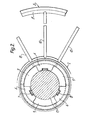
- Fig. 2 Eine Draufsicht auf ein Rotetionsscheibenfilterelement.
- 1 shows a schematic diagram of two rotary disc filter elements arranged one above the other in section;
- Fig. 2 is a plan view of a Rotation disc filter element.
Der Kesselfilter, in den die erfindungsgemäßen Rotationsscheibe filterelemente 1 eingebaut sind, kann von bekannter Bauart sein, weshalb er nachfolgend nicht näher erläutert wird.The boiler filter, in which the rotary disk filter elements 1 according to the invention are installed, can be of a known type, which is why it is not explained in more detail below.
Ein Rotationsscheibenfilterelement1 setzt sich aus einer Nabe 2, einem Bodenblech 3, einem Stützgewebe 4 und einem Filtergewebe 5 zusammen. Mehrere Rotationsacheibenfilterelemente übereinander auf einer Zentralwelle 17 angeordnet bilden ein Filterpaket. Das Filterpaket ist über eine nicht gezeigte Einrichtung dichtend verspannt.A rotary disk filter element 1 is composed of a hub 2, a base plate 3, a support fabric 4 and a filter fabric 5. A plurality of rotary axis filter elements arranged one above the other on a
An einer Nabe 2 ist ein scheibenförmiges Bodenblech 3 befestigt. Darauf liegt ein Stützgewebe 4 über das ein Filtergewebe 5 gespannt ist. Das Stützgewebe 4 und das Filtergewebe 5 haben ein Mittelloch, das dem Durchmesser einer Bohrung der Nabe 2 entspricht und auch in diesem Bereich angeordnet ist.A disk-shaped base plate 3 is fastened to a hub 2. There is a support fabric 4 over which a filter fabric 5 is stretched. The supporting fabric 4 and the filter fabric 5 have a central hole which corresponds to the diameter of a bore in the hub 2 and is also arranged in this area.
An der Nabe 2 ist an einem unteren Vorsprung 18, der axial über den Außenumfang der Nabe 2 . herausragt, eine tiefgezogene Zarge 12 des Bodenbleches 3 angeschweißt. Auf einem oberen Vorsprung 19 der Nabe 2 liegt das Stützgewebe 4 auf. Der obere Vorsprung 19 ist gegenüber dem unteren Vorsprung 18 zurückversetzt. Dadurch ergibt sich zwischen der Nabe 2 und der tiefgezogenen Zarge 12 ein freier Ringraum, der einen Sammelkanal 13 bildet. Waagrechte Bohrungen 20 in der Nabe 2; gleichmäßig durch die Nabe 2 angebracht, verbinden den Sammelkanal 13 mit einem Filtratabführkanal 9.On the hub 2 is on a
Der Abführkanal 9 wird dadurch gebildet, daß der Durchmesser der Bohrung der Nabe 2 größer ist, als der Außendurchmesser der Zentralwelle 17. Zur Zentrierung der Nabe 2 auf der Zentralwelle 17 sind in der Innenbohrung der Nabe 2 je drei gleichdemensionierte Distanzstücke 6 angeschweißt. In jedem Distanzstück 6 ist je eine Führungsnut 7 eingefräst, in die ein Mitnehmerkeil 8 der Zentralwelle 17 eingreift.The
Das Bodenblech 3 erstreckt sich nach der tiefgezogenen Zarge 12 horizontal bis zu seinem Außenrand. In dieses Bodenblech 3 sind im Winkel von 30° zwölf radiale Sicken 10 tiefgezogen. In der Nähe des Außenrandes befindet sich
eine koaxiale Sicke 11. Die koaxiale Sicke 11 ist mit dem Sammelkanal 13 durch die zwölf radialen Sicken 10 verbunden. Die radialen Sicken 10 besitzen ein Gefälle von der koaxialen Sicke 11 zum Sammelkanal 13 hin.The bottom plate 3 extends after the deep-drawn
a
Am Außenumfang des Bodenbleches 3 ist dieses hinter der koaxialen Sicke 11 im gleichen Niveau, wie vor der koaxialen Sicke 11 etwa 10 mm weiter geführt. Anschließend ist es genau um die Höhe des Stützgewebes 4 schräg nach oben gebogen, um nach einer weitern Biegung wieder horizontal zu verlaufen. Auf diese Weise wird innerhalb einer Verlängerung 24 eine Auflagefläche 25 für das Stützgewebe 4 gebildet.On the outer circumference of the base plate 3, it is guided behind the
Wie aus Fig. 1 ersichtlich wird der Trubraum 16 durch den Abstand zwischen dem Filtergewebe 5 des unteren Rotationascheibenfilterelementes und der Unterseite des Bodenbleches 3 des nächstfolgenden Rotationsscheibenfilterelementes gebildet.As can be seen from FIG. 1, the turbidity chamber 16 is formed by the distance between the filter fabric 5 of the lower rotary disk filter element and the underside of the bottom plate 3 of the next rotary disk filter element.
Die Abdichtung zwischen den Rotationsscheibenfilterelementen 1 erfolgt an der Nabe 2. Jeweils an der Unterseite befindet sich dort eine Nut, in die eine ringförmige Schwalbenschwanzdichtung 15 eingelegt ist.The seal between the rotary disk filter elements 1 takes place on the hub 2. There is a groove on the underside in each case, into which an
Zur Randabdichtung eines Rotationsscheibenfilterelementes ist über dem Filtergewebe 5, das um den Rand des Bodenbleches 3 herumgebogen ist, eine etwa U-förmige Ringdichtung 21 geschoben. Ein ebenfalls etwa U-förmiger Spannring 22 presst die Ringdichtung 21 flüssigkeitsdichtend um den Außenumfang des Bodenbleches.For the edge sealing of a rotary disk filter element, an approximately
Funktion des erfindungsgemäßen Gegenstandes:Function of the object according to the invention:
Vor Beginn der Filtration wird auf dap Filtergewebe 5 eine Grund- oder auch Voranschwemmung genannt, aufgebracht. Diese besteht aus einem. Filterhilfsmittel wie z.B. Diatomeenerde, Perlite, Aktivkohle oder irgendeinem Granulat oder ähnliche, Mit dieser Voranschwemmung wird eine Schutzschicht auf das Filtergewebe 5 gelegt, um zu verhindern, daß Filtrationsrückstände sich in das Filtergewebe 5 einlagern und dieses dadurch verstopfen.Before the start of the filtration, a basic or also pre-wash is applied to dap filter fabric 5. This consists of one. Filter aids such as diatomaceous earth, perlite, activated carbon or some granulate or the like. With this precoat, a protective layer is placed on the filter fabric 5 in order to prevent filtration residues accumulate in the filter fabric 5 and block it.
Das Filterhilfsmittel wird einer Trägerflüssigkeit, beispielsweise Wasser, beidosiert und im "Kreislauf" durch den Kesselfilter gepumpt. Diese Suspension bestehend aus Trägerflüssigkeit und Filterhilfsmittel gelangt in den Trubraum 16. Während die Trägerflüssigkeit das Filtergewebe'5 und das Stützgewebe 4 durchläuft und über das Bodenblech 3 und die hierin befindlichen Sicken 10 und 11 zum Sammelkanal 13 fließt und von da durch die Bohrungen 20 der Nabe 2 in dem Filtratabführkanal zusammenläuft, setzt sich das Filterhilfsmittel in einer gleichmäßigen Schicht auf dem Filtergewebe 5 ab. Durch das Nichtvorhandensein der nach dem Stand der Technik notwendigen Stützfüßchen, in Folge der Versteifung des Bodenbleches durch die radialen Sicken 10, tritt keine Wirbelbildung im Bereich der Anschwemmfläche mehr auf, die bisher nach dem Stand der Technik zu Abspülungen in der Anschwemmschicht und damit zu einer ungleichmäßig dicken Grundanschwemmung geführt haben.The filter aid is added to a carrier liquid, for example water, and pumped in a "circuit" through the boiler filter. This suspension consisting passes out of carrier liquid and filter aid in the filling space 16. While the carrier liquid passes through the filter fabric '5 and the support fabric 4 and flows via the bottom plate 3 and the beads situated therein 10 and 11 to the collection channel 13 and from there through the
Die im Bodenblech 3 an dessen Oberseite durch die Sicken gebildeten Vertiefungsrillen bewirken, daß entsprechend dem gleichmäßigen Abfluß auch der Durchtritt der Flüssigkeit durch das Filtergewebe'5 gleichmäßig an jeder Stelle des Filtergewebes erfolgt. Dadurch findet auf den Scheibenfilterelementen auch eine gleichmäßige Sedimentation an der Filtergewebeoberfläche statt.The deepening grooves formed in the bottom plate 3 on the upper side thereof by the beads have the effect that, in accordance with the uniform outflow, the liquid also passes through the filter fabric 5 uniformly at every point of the filter fabric. As a result, there is even sedimentation on the filter fabric surface on the disc filter elements.
Erfindungsgemäß wird so, durch einen gleichmäßigen Filterkuchenaufbau, die optimale freie Filterfläche auch über die gesamte Filtrationsdauer bis zur Erschöpfung des Trubraumes 16 aufrechterhalten. Es wird dabei selbstverständlich eine gleichmäßige optimale Dosierung von Filterhilfsmitteln über den gesamten Filtrationszyklus als gegeben vorausgesetzt. Nur nebenbei sei erwähnt, daß sich ein Zusatz von Filterhilfsmitteln in den Fällen erübrigt, wo das Unfiltrat schon genügend, den Filterkuchen auflockernde Substanzen enthält.According to the invention, the optimal free filter area is maintained over the entire filtration period until the trub 16 is exhausted by a uniform filter cake structure. Of course, a uniform, optimal dosage of filter aids over the entire filtration cycle is assumed as given. By the way, it should be mentioned that there is no need to add filter aids in cases where the unfiltrate already contains sufficient substances that loosen the filter cake.
Nach Beendigung der Filtration wird der Filterkuchen - der Rückstand, durch die Zentrifugalkraft der rotierenden Scheibenfilterelemente abgeschleudert. Störende Einbauten, gemäß dem Stand der Technik behindern bei der erfindungsgemäßen Vorrichtun nicht. In sehr kurzer Zeit sind die festen Bestandteile vom Filtergewebe 5 entfernt. Anschließend erfolgt eine Rückspülung. Noch anhaftende Partikel werden frei. und'weggespült. Die Rückspülung erfolgt gegen die Filtrationsrichtung. Durch wechselseitige Reinigungsmethode Wasser u. Zentrifugalkraft dringt Zwangsweise Wasserkieselgurgemisch zwischen Bodenblech u. Feingewebe. Dabei werden KG Teilchen während der nun folgenden Rotation an den Außenwand des Elementes geschleudert.After the filtration is finished, the filter cake - the residue - is thrown off by the centrifugal force of the rotating disc filter elements. Interfering installations, according to the prior art, do not hinder the device according to the invention. The solid components are removed from the filter fabric 5 in a very short time. Then backwashing takes place. Particles that are still adhering are released. and'washed away. Backwashing takes place against the direction of filtration. By mutual cleaning method water u. Centrifugal force forces water silicate mixture between the bottom plate u. Fine tissue. KG particles are thrown onto the outer wall of the element during the rotation that follows.
Da, wie aus der Praxis bekannt, einerseits die Korngrößenverteilung im Filterhilfsmittel starken Schwankungen unterworfen ist und andererseits die Porengröße des Filtergewebes 5 größer ist als ein Großteil der Filterhilfsmittelpartikel, werden bis zum Aufbau der die filtrierende Wirkung hervorrufende "Brückenbildung" mehr oder weniger viele Filterhilfsmittelteilchen durch das Filtergewebe 5 hindurchwandern. In Folge ihres relativ hohen spezifischen Gewichtes setzen sich diese Teilchen auf dem Stützgewebe 4 und der Oberfläche des Bodenbleches 3 ab. Die Fließgeschwindigkeit des Filtrates ist zu gering, um diese Ablagerungen am Außenwand während des Filtratflußes mitzureißen. Demzufolge liegen diese Teilchen nach beendeter Filtration unverändert an ihrem eingenommenen Platz.Since, as is known from practice, on the one hand the grain size distribution in the filter aid is subject to strong fluctuations and on the other hand the pore size of the filter fabric 5 is larger than a large part of the filter aid particles, more or less many filter aid particles become through until the "bridge formation" which causes the filtering effect is built up migrate through the filter fabric 5. As a result of their relatively high specific weight these particles settle on the support fabric 4 and the surface of the floor panel 3. The flow rate of the filtrate is too slow to entrain these deposits on the outer wall during the filtrate flow. As a result, these particles remain unchanged in their occupied position after the filtration has ended.
Durch die Rotation der Scheibenfilterelemente zum Zwecke der Kuchenentfernung werden diese Teilchen, die zwischen dem Bodenblech 3 und dem Filtergewebe 5 liegen an den äußeren Dichtrand des Rotationsscheibenfilterelementes geschleudert und sinken bei Stillstand dieses Elementes in die koaxiale Sicke 11. Dort werden sie von der zuerst durch die radialen Sicken 10 einströmende Rückspülflüssigkeit aufgewirbelt und freigeströmt. Bei der folgenden Spülung in Filtrationsrichtung, die ein Vielfaches der Fließgeschwindigkeit der Filtrationsgeschvindigkeit hat, werden die lockeren Filterhilfsmittelteilchen mitgerissen und aus dem Inneren der Rotationsscheibenfilterelemente herausbefördert. Das Gefälle innerhalb der radialen Sicken 10 wirkt hierzu unterstützend.Due to the rotation of the disc filter elements for the purpose of cake removal, these particles, which lie between the base plate 3 and the filter fabric 5, are thrown against the outer sealing edge of the rotary disc filter element and sink into the
Bei Rotationsscheibenfilterelementen ohne die erfindungsgemäßen Sicken 10 und 11 war ein Entfernen dieser " Einlagerungen" nicht ohne mechanische Hilfe, wie z.B. Ausspritzen mit einem "Dampfstrahl", der zuvor aus dem Kessel ausgebauten Rotationsscheibenfilterelemente nicht möglich. Vielmehr haben sich diese Teilchen zwischen dem Bodenblech 3 und dem Filtergewebe 5 am äußeren Dichtrand gleichmäßig festgesetzt und ineinander verkeilt und zunehmend zu einer wulstartigen Erhöhung des Filtergewebes 5 im gesamten Randbereich geführt.In the case of rotary disk filter elements without the
Nicht nur daß das gespannte Filtergewebe gedehnt wurde mit der Folge einer Gefügeveränderung in den Durchgangskanälen des Gewebes, sondern auch daß die wirksame Filterfläche dadurch erheblich verkelinert wurde. Durch diese Erscheinung treten darüberhinaus biologische Probleme auf.Not only was the tensioned filter fabric stretched, resulting in a change in the structure of the through-channels of the fabric, but also that the effective filter area was significantly reduced. This phenomenon also causes biological problems.
Die Rotationsscheibenfilterelemente können völlig leerlaufen durch das Gefälle, das die radialen Sicken 10 zum Sammelkanal 13 hin aufweisen. Dies ist insbesonders bei entsprechenden Verfahren und teueren Filtraten von Wichtigkeit.The rotary disc filter elements can run completely empty due to the gradient that the
Durch die Variabilität der lichten Höhe zwischen zwei übereinander angeordneten Rotationsscheibenfilterelementen kann dre Trubraum 16 verändert werden und damit dem unterschiedlichen Trub- oder Rückstandsanfall angepasst werden. Diese Möglichkeit, die bei Vorrichtungen nach dem Stande der Technik nicht gegeben ist, weil die Stützfüßchen nicht höhenverstellbar sind - erlaubt es durch einfaches Umrüsten der Filter für die Filtration verschiedener Filtermedien einzusetzen.Due to the variability of the clear height between two rotary disc filter elements arranged one above the other, three turbidity space 16 can be changed and thus adapted to the different turbidity or residue accumulation. This possibility, which is not available in devices according to the prior art, because the support feet cannot be adjusted in height - allows the filter to be used for the filtration of various filter media by simply converting them.
Claims (17)
dadurch gekennzeichnet, daß die Versteifung durch Sicken (10 + 11) gebildet ist.2) Large-area rotary disc filter element for the boiler filter according to claim 1
characterized in that the stiffening is formed by beads (10 + 11).
dadurch gekennzeichnet, daß die Verlängerung (24) hinter der Auflagefläche (25) um die Höhe des Stützgewebes (4) schräg nach oben gebogen ist und nach einer weiteren Biegung wieder horizontal verläuft.14) Large-area rotary disk filter element for the boiler filter according to claim 13
characterized in that the extension (24) behind the support surface (25) is bent obliquely upwards by the height of the supporting fabric (4) and is horizontal again after another bend.
dadurch gekennzeichnet, daß durch Anordnung eines Distanzringes (23) zwischen zwei übereinander angeordneten großflächigen Rotationsscheibenfilterelementen der freie Raum (16) zur Aufnahme des Filterkuchens beliebig einstellbar ist.15) Large-area rotating disk filter element for boiler filter according to one of claims 1-14
characterized in that the free space (16) for receiving the filter cake can be set as desired by arranging a spacer ring (23) between two large-area rotary disc filter elements arranged one above the other.
dadurch gekennzeichnet, daß die koaxiale Sicke (11) im Randbereich des Außenumfanges des Bodenbleches (3) beim Rückspülen einen Freiströmkanal bildet, der mit den im wesentlichen radialen Sicken (10) und dem Sammelkanal (13) verbunden ist.16) Method for operating a large-area rotary disk filter element for a boiler filter according to one of claims 1-15
characterized in that the coaxial bead (11) in the edge region of the outer circumference of the base plate (3) forms a free-flow channel during backwashing, which is connected to the essentially radial beads (10) and the collecting channel (13).
dadurch gekennzeichn et, daß die radialen Sicken (10) und die koaxialen Sicken (11) zusammen mit dem Sammelkanal (13) ein laminares Zu- und Ablaufsystem zum Zu- und Ableiten von Filtrat und Spülflüssigkeit bilden.17) Method according to claim 16
characterized gekennzeichn et that the radial beads (10) and the coaxial beads (11) together with the collecting channel (13) form a laminar inlet and outlet system for the supply and discharge of filtrate and rinsing liquid.
Priority Applications (1)
| Application Number | Priority Date | Filing Date | Title |
|---|---|---|---|
| AT83103639T ATE23117T1 (en) | 1982-08-31 | 1983-04-14 | LARGE-SCALE ROTATION DISC FILTER ELEMENT FOR BOILER FILTER. |
Applications Claiming Priority (2)
| Application Number | Priority Date | Filing Date | Title |
|---|---|---|---|
| DE19823232354 DE3232354A1 (en) | 1982-08-31 | 1982-08-31 | LARGE AREA ROTATING DISC FILTER ELEMENT FOR BOILER FILTER AND METHOD FOR OPERATING SUCH A ROTATING DISC FILTER ELEMENT |
| DE3232354 | 1982-08-31 |
Publications (3)
| Publication Number | Publication Date |
|---|---|
| EP0104307A2 true EP0104307A2 (en) | 1984-04-04 |
| EP0104307A3 EP0104307A3 (en) | 1985-01-09 |
| EP0104307B1 EP0104307B1 (en) | 1986-10-29 |
Family
ID=6172142
Family Applications (1)
| Application Number | Title | Priority Date | Filing Date |
|---|---|---|---|
| EP83103639A Expired EP0104307B1 (en) | 1982-08-31 | 1983-04-14 | Large-surface rotating disc filter element in a tank |
Country Status (6)
| Country | Link |
|---|---|
| US (1) | US4708797A (en) |
| EP (1) | EP0104307B1 (en) |
| JP (1) | JPS5962318A (en) |
| AT (1) | ATE23117T1 (en) |
| BR (1) | BR8302746A (en) |
| DE (2) | DE3232354A1 (en) |
Cited By (1)
| Publication number | Priority date | Publication date | Assignee | Title |
|---|---|---|---|---|
| CN108579199A (en) * | 2018-04-23 | 2018-09-28 | 扬州浪涛清环保科技有限公司 | A kind of blue algae filter |
Families Citing this family (17)
| Publication number | Priority date | Publication date | Assignee | Title |
|---|---|---|---|---|
| DE3405483A1 (en) * | 1984-02-16 | 1985-08-22 | Grau Feinwerktechnik GmbH & Co, 7926 Böhmenkirch | Rotary disc filter element for boiler filters |
| DE3529706A1 (en) * | 1985-08-20 | 1987-03-05 | Schenk Filterbau Gmbh | DISC FILTER FOR FILTRATION OF LIQUIDS |
| DE3801396A1 (en) * | 1988-01-20 | 1989-08-03 | Grau Gmbh & Co Holdingges | DISC FILTER |
| JPH0244330U (en) * | 1988-09-19 | 1990-03-27 | ||
| DE8904306U1 (en) * | 1989-04-07 | 1989-06-22 | Heinrich Fiedler GmbH & Co. KG, 8400 Regensburg | Disc filter consisting of individual disc filter segments |
| DE4039890C1 (en) * | 1990-12-13 | 1992-04-09 | Anton Steinecker Entwicklungs-Gmbh & Co., 8050 Freising, De | |
| US5254250A (en) * | 1991-05-30 | 1993-10-19 | Membrex, Inc. | Rotary filtration device and filter pack therefor |
| US5679249A (en) * | 1991-12-24 | 1997-10-21 | Pall Corporation | Dynamic filter system |
| US5242590A (en) * | 1992-07-31 | 1993-09-07 | Ingersoll-Rand Company | Lightweight, anti-rewet, modular style disc sector |
| US6117322A (en) * | 1993-06-23 | 2000-09-12 | Pall Corporation | Dynamic filter system |
| US5647982A (en) * | 1995-05-10 | 1997-07-15 | Haythornthwaite; James (Jimmy) | Vacuum filter element |
| US5707517A (en) * | 1995-11-27 | 1998-01-13 | Membrex, Inc. | Immersible rotary disc filtration device |
| DE19602348C1 (en) * | 1996-01-24 | 1997-09-11 | Schenk Filterbau Gmbh | Disc filter |
| DE19804494C2 (en) | 1998-02-05 | 2002-02-07 | Schenk Filterbau Gmbh | Filter element for horizontal disc filters |
| US5993674A (en) * | 1998-02-24 | 1999-11-30 | Membrex, Inc. | Rotary disc filtration device with means to reduce axial forces |
| US7396462B2 (en) * | 2005-10-18 | 2008-07-08 | Chi-Chang Kuo | Filtering device |
| FI123461B (en) * | 2011-04-20 | 2013-05-15 | Jeven Oy | Air Filter |
Family Cites Families (14)
| Publication number | Priority date | Publication date | Assignee | Title |
|---|---|---|---|---|
| DE319500C (en) * | 1917-04-25 | 1920-03-06 | Enzinger Werke Akt Ges | Distribution plate for candle filter presses |
| GB763495A (en) * | 1954-04-08 | 1956-12-12 | Gen Motors Ltd | Improvements in fluid filters |
| DE1245907B (en) * | 1964-01-22 | 1967-08-03 | Erlenbach Dr.-Ing Hans Müller (Schweiz) | Disc-shaped filter element |
| US3319794A (en) * | 1965-10-23 | 1967-05-16 | Richard P Gross | Horizontal plate filter |
| US3387711A (en) * | 1967-09-13 | 1968-06-11 | Sherwood A. Rickert | Horizontal, multiple plate filter assembly |
| CH479324A (en) * | 1968-09-11 | 1969-10-15 | Chemap Ag | Sealing arrangement for disc filter elements with central filtrate drain |
| US3572382A (en) * | 1969-01-31 | 1971-03-23 | Fred J Luthe | Single-ported double-seated valve mechanism |
| DE2321320A1 (en) * | 1973-04-27 | 1974-11-14 | Hoechst Ag | FILTER PACKAGE |
| CH564962A5 (en) * | 1973-07-19 | 1975-08-15 | Mueller Hans Maennedorf | |
| DE2705046A1 (en) * | 1977-02-08 | 1978-08-10 | Schenk Filterbau Gmbh | METHOD AND DEVICE FOR FILTRATING LIQUIDS |
| DE7809827U1 (en) * | 1977-04-07 | 1978-07-20 | Chemap Ag, Maennedorf, Zuerich (Schweiz) | FILTER ELEMENT |
| CH615357A5 (en) * | 1977-04-07 | 1980-01-31 | Chemap Ag | Filter element |
| DE2846216A1 (en) * | 1978-10-24 | 1980-05-08 | Schenk Filterbau Gmbh | Disc filter element for corrosive media - has radial and concentric grooves on plastic support disc |
| US4282094A (en) * | 1980-01-07 | 1981-08-04 | Charles F. Betz | Filtering apparatus |
-
1982
- 1982-08-31 DE DE19823232354 patent/DE3232354A1/en not_active Withdrawn
-
1983
- 1983-04-14 AT AT83103639T patent/ATE23117T1/en not_active IP Right Cessation
- 1983-04-14 EP EP83103639A patent/EP0104307B1/en not_active Expired
- 1983-04-14 DE DE8383103639T patent/DE3367168D1/en not_active Expired
- 1983-05-25 BR BR8302746A patent/BR8302746A/en unknown
- 1983-07-01 US US06/510,417 patent/US4708797A/en not_active Expired - Lifetime
- 1983-08-31 JP JP58160212A patent/JPS5962318A/en active Granted
Cited By (1)
| Publication number | Priority date | Publication date | Assignee | Title |
|---|---|---|---|---|
| CN108579199A (en) * | 2018-04-23 | 2018-09-28 | 扬州浪涛清环保科技有限公司 | A kind of blue algae filter |
Also Published As
| Publication number | Publication date |
|---|---|
| JPS625643B2 (en) | 1987-02-05 |
| EP0104307A3 (en) | 1985-01-09 |
| ATE23117T1 (en) | 1986-11-15 |
| JPS5962318A (en) | 1984-04-09 |
| US4708797A (en) | 1987-11-24 |
| EP0104307B1 (en) | 1986-10-29 |
| DE3367168D1 (en) | 1986-12-04 |
| BR8302746A (en) | 1984-06-12 |
| DE3232354A1 (en) | 1984-03-01 |
Similar Documents
| Publication | Publication Date | Title |
|---|---|---|
| EP0104307A2 (en) | Large-surface rotating disc filter element in a tank | |
| EP0291538B1 (en) | Process and apparatus for the continuous filtration of liquids | |
| DE2629848A1 (en) | PROCESS FOR FILTERING COAT LIQUIDS AND DEVICE FOR CARRYING OUT THE PROCESS | |
| DE3883987T2 (en) | nerfahr and device for filtering impurities. | |
| WO1998006473A1 (en) | Device for continuous filtration of liquids | |
| EP0155466B1 (en) | Filter for the separation of solids from liquids | |
| DE1088469B (en) | Method and device for the continuous separation of solids from liquids and their removal from the filter | |
| DE2446849A1 (en) | METHOD AND DEVICE FOR REGENERATING A LIQUID FILTER | |
| EP0086770B1 (en) | Filter apparatus, especially adapted for the filtration of drinks | |
| EP0379054B1 (en) | Filter device | |
| DE2042353B2 (en) | Device for filtering liquids | |
| DE1410811B1 (en) | Method and device for cleaning dirt-contaminated solvent produced in a chemical cleaning machine | |
| DE2705046A1 (en) | METHOD AND DEVICE FOR FILTRATING LIQUIDS | |
| EP0925817B1 (en) | Rinsable filter | |
| DE2924794C2 (en) | Device for dewatering a fiber suspension | |
| EP0650753B2 (en) | Bach-wash filtration device | |
| DE2756892C2 (en) | Centrifugal cleaning filter | |
| DE3336132C2 (en) | ||
| DE3423040C2 (en) | ||
| DE1611100B1 (en) | Filter plate for a pressure filter device with a rocking device loosing the filter cake | |
| DE3875592T2 (en) | ROTATING FILTER WITH OUTER FILTRATE PIPES. | |
| EP0153985A2 (en) | Process and apparatus for backwashing a filter | |
| DE60110163T2 (en) | Method and apparatus for backwashing sand filter bed units | |
| DE3405483C2 (en) | ||
| DE2257357A1 (en) | PROCESS AND DEVICE FOR CONTINUOUS OPERATION OF A ROTATABLE FILTER, PARTIALLY IMMERSED IN A TREATMENT SLUDGE BATH, OF ONE OR MORE DISCS OR OF A DRUM |
Legal Events
| Date | Code | Title | Description |
|---|---|---|---|
| PUAI | Public reference made under article 153(3) epc to a published international application that has entered the european phase |
Free format text: ORIGINAL CODE: 0009012 |
|
| AK | Designated contracting states |
Designated state(s): AT CH DE FR GB LI NL |
|
| PUAL | Search report despatched |
Free format text: ORIGINAL CODE: 0009013 |
|
| AK | Designated contracting states |
Designated state(s): AT CH DE FR GB LI NL |
|
| 17P | Request for examination filed |
Effective date: 19850705 |
|
| 17Q | First examination report despatched |
Effective date: 19860121 |
|
| GRAA | (expected) grant |
Free format text: ORIGINAL CODE: 0009210 |
|
| AK | Designated contracting states |
Kind code of ref document: B1 Designated state(s): AT CH DE FR GB LI NL |
|
| REF | Corresponds to: |
Ref document number: 23117 Country of ref document: AT Date of ref document: 19861115 Kind code of ref document: T |
|
| ET | Fr: translation filed | ||
| REF | Corresponds to: |
Ref document number: 3367168 Country of ref document: DE Date of ref document: 19861204 |
|
| PLBE | No opposition filed within time limit |
Free format text: ORIGINAL CODE: 0009261 |
|
| STAA | Information on the status of an ep patent application or granted ep patent |
Free format text: STATUS: NO OPPOSITION FILED WITHIN TIME LIMIT |
|
| 26N | No opposition filed | ||
| PGFP | Annual fee paid to national office [announced via postgrant information from national office to epo] |
Ref country code: FR Payment date: 19960311 Year of fee payment: 14 |
|
| PGFP | Annual fee paid to national office [announced via postgrant information from national office to epo] |
Ref country code: AT Payment date: 19960314 Year of fee payment: 14 |
|
| PGFP | Annual fee paid to national office [announced via postgrant information from national office to epo] |
Ref country code: GB Payment date: 19960319 Year of fee payment: 14 |
|
| PGFP | Annual fee paid to national office [announced via postgrant information from national office to epo] |
Ref country code: NL Payment date: 19960322 Year of fee payment: 14 |
|
| PG25 | Lapsed in a contracting state [announced via postgrant information from national office to epo] |
Ref country code: GB Effective date: 19970414 Ref country code: AT Effective date: 19970414 |
|
| PG25 | Lapsed in a contracting state [announced via postgrant information from national office to epo] |
Ref country code: NL Effective date: 19971101 |
|
| GBPC | Gb: european patent ceased through non-payment of renewal fee |
Effective date: 19970414 |
|
| PG25 | Lapsed in a contracting state [announced via postgrant information from national office to epo] |
Ref country code: FR Free format text: LAPSE BECAUSE OF NON-PAYMENT OF DUE FEES Effective date: 19971231 |
|
| NLV4 | Nl: lapsed or anulled due to non-payment of the annual fee |
Effective date: 19971101 |
|
| REG | Reference to a national code |
Ref country code: FR Ref legal event code: ST |
|
| PGFP | Annual fee paid to national office [announced via postgrant information from national office to epo] |
Ref country code: DE Payment date: 20011228 Year of fee payment: 20 |
|
| PGFP | Annual fee paid to national office [announced via postgrant information from national office to epo] |
Ref country code: CH Payment date: 20020314 Year of fee payment: 20 |
|
| PG25 | Lapsed in a contracting state [announced via postgrant information from national office to epo] |
Ref country code: LI Free format text: LAPSE BECAUSE OF EXPIRATION OF PROTECTION Effective date: 20030413 Ref country code: CH Free format text: LAPSE BECAUSE OF EXPIRATION OF PROTECTION Effective date: 20030413 |
|
| REG | Reference to a national code |
Ref country code: CH Ref legal event code: PL |