EP0104307A2 - Elément de filtration sous forme de disque rotatif à grande surface dans une enceinte - Google Patents
Elément de filtration sous forme de disque rotatif à grande surface dans une enceinte Download PDFInfo
- Publication number
- EP0104307A2 EP0104307A2 EP83103639A EP83103639A EP0104307A2 EP 0104307 A2 EP0104307 A2 EP 0104307A2 EP 83103639 A EP83103639 A EP 83103639A EP 83103639 A EP83103639 A EP 83103639A EP 0104307 A2 EP0104307 A2 EP 0104307A2
- Authority
- EP
- European Patent Office
- Prior art keywords
- filter
- filter element
- boiler
- area
- beads
- Prior art date
- Legal status (The legal status is an assumption and is not a legal conclusion. Google has not performed a legal analysis and makes no representation as to the accuracy of the status listed.)
- Granted
Links
Images

Classifications
-
- B—PERFORMING OPERATIONS; TRANSPORTING
- B01—PHYSICAL OR CHEMICAL PROCESSES OR APPARATUS IN GENERAL
- B01D—SEPARATION
- B01D37/00—Processes of filtration
- B01D37/02—Precoating the filter medium; Addition of filter aids to the liquid being filtered
-
- B—PERFORMING OPERATIONS; TRANSPORTING
- B01—PHYSICAL OR CHEMICAL PROCESSES OR APPARATUS IN GENERAL
- B01D—SEPARATION
- B01D29/00—Filters with filtering elements stationary during filtration, e.g. pressure or suction filters, not covered by groups B01D24/00 - B01D27/00; Filtering elements therefor
- B01D29/39—Filters with filtering elements stationary during filtration, e.g. pressure or suction filters, not covered by groups B01D24/00 - B01D27/00; Filtering elements therefor with hollow discs side by side on, or around, one or more tubes, e.g. of the leaf type
- B01D29/41—Filters with filtering elements stationary during filtration, e.g. pressure or suction filters, not covered by groups B01D24/00 - B01D27/00; Filtering elements therefor with hollow discs side by side on, or around, one or more tubes, e.g. of the leaf type mounted transversely on the tube
- B01D29/416—Filtering tables
-
- B—PERFORMING OPERATIONS; TRANSPORTING
- B01—PHYSICAL OR CHEMICAL PROCESSES OR APPARATUS IN GENERAL
- B01D—SEPARATION
- B01D29/00—Filters with filtering elements stationary during filtration, e.g. pressure or suction filters, not covered by groups B01D24/00 - B01D27/00; Filtering elements therefor
- B01D29/62—Regenerating the filter material in the filter
- B01D29/70—Regenerating the filter material in the filter by forces created by movement of the filter element
- B01D29/74—Regenerating the filter material in the filter by forces created by movement of the filter element involving centrifugal force
-
- B—PERFORMING OPERATIONS; TRANSPORTING
- B01—PHYSICAL OR CHEMICAL PROCESSES OR APPARATUS IN GENERAL
- B01D—SEPARATION
- B01D33/00—Filters with filtering elements which move during the filtering operation
- B01D33/15—Filters with filtering elements which move during the filtering operation with rotary plane filtering surfaces
- B01D33/17—Filters with filtering elements which move during the filtering operation with rotary plane filtering surfaces with rotary filtering tables
Definitions
- the invention relates to a large-area rotary disk filter element for boiler filters with a hub,
- a circular base plate attached to it, a filter fabric stretched over it and a support fabric arranged between the base plate and the filter fabric.
- rotary disk filter elements are filter media in pressure-loaded boiler filters, such as in US Pat. No. 4,201,670 or in the DE-OS of the same name 27 05 046.
- the individual rotary disc filter elements are arranged on a central shaft and tightly clamped together. All rotary disc filter elements - together form a filter package.
- Rotating disc filter elements have the task of separating impurities from an unfiltrate and draining off the bare filtrate. The distance between the rotating disk filter elements is determined by the height of the hub.
- the separated filtration residues settle on the upper filter fabric of the rotating disc filter elements and form the filter cake.
- the filter cake grows and becomes thicker.
- the height of the total filter cake that builds up is determined by the distance between two rotary disc filter elements that are one above the other.
- the filter pack is set in rotation to remove the filter cake from the disc filter elements.
- the filter cake is removed from the rotating disk filter elements by the centrifugal force.
- the filter cake has a very considerable weight. It lies on the surface of each rotary disc filter element. So far, the rotations have been used so that the individual rotary disc filter elements cannot twist, bend or kink under the load of the filter cake disc filter elements with feet are supported on the rotating disc filter element underneath. These support feet are spaced evenly over the entire outer circumference of each rotary disc filter element.
- a disadvantage of this support is that the support feet cause a vortex formation in the area of each support foot when a basic deposit is applied to the filter fabric while the filter pack rotates slowly, so that washdowns occur in the vortex area or there is no basic deposit on the filter fabric at all.
- bad filtrate or g.ar unfiltrate penetrates into the filtrate and contaminates it.
- Only an even filter cake build-up guarantees from the beginning a constant effective free filter area over the entire duration of a filtration batch and thus a uniform hourly and total quantity output. Washed-off or bare spots quickly clog the tissue and thus reduce the free effective filter area.
- the support feet are namely the filter to be thrown off by centrifugal force cake in the way and prevent the cake pieces from sliding freely. More or less large sections are held by the feet. This creates an imbalance in the rotating filter package, which results in considerable damage to the machine and the building. In the case of filter cakes with a higher viscosity, it can even happen that the support feet are bent outwards or break off completely. It is not uncommon for the filter elements not to be 100% cleaned, despite the fact that they have been rotating for a long time, and that there are still cake residues in the area of the feet.
- the object of the present invention is to provide a large-area rotary disk filter element which, with simple means, ensures high stability with a better wash-up at the same time and trouble-free and flawless cleaning, as well as a rational method for operating such a rotary disk filter element.
- the stiffening is advantageously formed by beads which run essentially radially and coaxially to the central axis of the filter kettle.
- This measure according to the invention has the decisive advantage over known rotary disk filter elements that there are no interfering support devices. The resulting flooding is prevented and there are no difficulties with cleaning.
- the base plate is deep-drawn in a frame-like manner in the region of the hub of the central ring and a coaxial bead is arranged at least in the edge region of the outer circumference of the base plate, the radial beads extending from the deep-drawn frame on the hub to the coaxial bead located on the outer circumference of the base plate extends.
- the radial beads are arranged uniformly and at the same angular distance of 15 ° to 60 °, preferably 30 °, over the entire surface of the base plate.
- the radial beads have a slope towards the hub, while the actual base plate runs completely horizontally.
- the arrangement of a spacer ring between two large-area rotating disk filter elements arranged one above the other allows the free space for receiving the filter cake and the trub space to be set as desired.
- the goal is to vary the turbidity area accordingly and to adapt the total filter output to the filter medium. This results in a greater use of the machine through a product and / or filtration type-related adjustment. Filtration costs are reduced in this way, which increases overall profitability.
- This facility was not available in devices corresponding to the prior art, because the trub space was rigidly predetermined and thus fixed by the height of the support legs and only an exchange of the entire tensioning unit for the filter fabric was necessary to change the trub space. This caused a very considerable expense.
- a method according to the invention is characterized in a rotary disk filter element described at the outset in that the coaxial bead in the edge region of the outer periphery of the base plate forms a free-flow channel during backwashing, which is connected to the essentially radial beads and the frame-like recess.
- This frame-like depression of the base plate forms a filtrate collecting channel around the hub for draining off the filtrate through drain holes evenly arranged in the hub.
- the radial depressions form a laminar drain system for draining off the filtrate.
- This drainage system ensures a uniform filtrate drainage within a rotating disc filter element.
- the entire surface of the rotary disk filter element or the built-up filter cake is filtered uniformly over the entire area, so that the cake is evenly built up over the entire area. The goal is thus achieved that a uniform filter cake build-up is achieved by this discharge flow.
- this inlet and outlet system also solves the problem of removing filter aid deposits between the filter fabric and the floor panel.
- the filter aids which have mostly penetrated the filter fabric when the first precoat is applied and have been lying on the bottom plate throughout the entire filtration period, were thrown into the coaxial bead on the outer circumference of the bottom plate during centrifugal cleaning. There they are whirled up and loosened up by the backwash liquid flowing in first through the radial beads, so that they are carried away by the subsequent wash water in the direction of filtration and washed away, i.e. be streamed free.
- the device according to the invention is a prerequisite for the method for solving the problem of avoiding deposits of filter aids between the base plate and the filter fabric.
- Such deposits have almost always led to the formation of beads in the area of the filter fabric tensioning device in the edge area of the filter element.
- intensive efforts by experts it was not possible to find a method to solve the problem. This problem is solved with what has been described here.
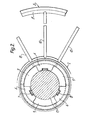
- the boiler filter in which the rotary disk filter elements 1 according to the invention are installed, can be of a known type, which is why it is not explained in more detail below.
- a rotary disk filter element 1 is composed of a hub 2, a base plate 3, a support fabric 4 and a filter fabric 5.
- a plurality of rotary axis filter elements arranged one above the other on a central shaft 17 form a filter package. The filter package is tightly clamped over a device, not shown.
- a disk-shaped base plate 3 is fastened to a hub 2.
- a support fabric 4 over which a filter fabric 5 is stretched.
- the supporting fabric 4 and the filter fabric 5 have a central hole which corresponds to the diameter of a bore in the hub 2 and is also arranged in this area.
- a lower projection 18 On the hub 2 is on a lower projection 18, which is axially over the outer circumference of the hub 2. protrudes, a deep drawn frame 12 of the bottom plate 3 welded.
- the supporting fabric 4 rests on an upper projection 19 of the hub 2.
- the upper projection 19 is set back from the lower projection 18. This results in a free annular space between the hub 2 and the deep-drawn frame 12, which forms a collecting channel 13.
- the discharge duct 9 is formed in that the diameter of the bore of the hub 2 is larger than the outer diameter of the central shaft 17.
- three equally dimensioned spacers 6 are welded into the inner bore of the hub 2.
- a guide groove 7 is milled into each spacer 6, in which a driver wedge 8 of the central shaft 17 engages.
- the bottom plate 3 extends after the deep-drawn frame 12 horizontally to its outer edge.
- twelve radial beads 10 are deep drawn at an angle of 30 °.
- the coaxial bead 11 is connected to the collecting duct 13 by the twelve radial beads 10.
- the radial beads 10 have a slope from the coaxial bead 11 to the collecting duct 13.
- the turbidity chamber 16 is formed by the distance between the filter fabric 5 of the lower rotary disk filter element and the underside of the bottom plate 3 of the next rotary disk filter element.
- the seal between the rotary disk filter elements 1 takes place on the hub 2. There is a groove on the underside in each case, into which an annular dovetail seal 15 is inserted.
- an approximately U-shaped ring seal 21 is pushed over the filter fabric 5, which is bent around the edge of the bottom plate 3.
- a likewise approximately U-shaped clamping ring 22 presses the ring seal 21 in a liquid-sealing manner around the outer circumference of the base plate.
- dap filter fabric 5 Before the start of the filtration, a basic or also pre-wash is applied to dap filter fabric 5. This consists of one. Filter aids such as diatomaceous earth, perlite, activated carbon or some granulate or the like. With this precoat, a protective layer is placed on the filter fabric 5 in order to prevent filtration residues accumulate in the filter fabric 5 and block it.
- the filter aid is added to a carrier liquid, for example water, and pumped in a "circuit" through the boiler filter.
- This suspension consisting passes out of carrier liquid and filter aid in the filling space 16. While the carrier liquid passes through the filter fabric '5 and the support fabric 4 and flows via the bottom plate 3 and the beads situated therein 10 and 11 to the collection channel 13 and from there through the bores 20 of the Hub 2 converges in the filtrate discharge channel, the filter aid settles on the filter fabric 5 in a uniform layer.
- the deepening grooves formed in the bottom plate 3 on the upper side thereof by the beads have the effect that, in accordance with the uniform outflow, the liquid also passes through the filter fabric 5 uniformly at every point of the filter fabric. As a result, there is even sedimentation on the filter fabric surface on the disc filter elements.
- the optimal free filter area is maintained over the entire filtration period until the trub 16 is exhausted by a uniform filter cake structure.
- a uniform, optimal dosage of filter aids over the entire filtration cycle is assumed as given.
- the filter cake - the residue - is thrown off by the centrifugal force of the rotating disc filter elements.
- Interfering installations according to the prior art, do not hinder the device according to the invention.
- the solid components are removed from the filter fabric 5 in a very short time. Then backwashing takes place. Particles that are still adhering are released. and'washed away. Backwashing takes place against the direction of filtration.
- water u Centrifugal force forces water silicate mixture between the bottom plate u. Fine tissue. KG particles are thrown onto the outer wall of the element during the rotation that follows.
- the grain size distribution in the filter aid is subject to strong fluctuations and on the other hand the pore size of the filter fabric 5 is larger than a large part of the filter aid particles, more or less many filter aid particles become through until the "bridge formation" which causes the filtering effect is built up migrate through the filter fabric 5.
- these particles settle on the support fabric 4 and the surface of the floor panel 3.
- the flow rate of the filtrate is too slow to entrain these deposits on the outer wall during the filtrate flow. As a result, these particles remain unchanged in their occupied position after the filtration has ended.
- the rotary disc filter elements can run completely empty due to the gradient that the radial beads 10 have towards the collecting duct 13. This is particularly important in the case of appropriate processes and expensive filtrates.
Landscapes
- Chemical & Material Sciences (AREA)
- Chemical Kinetics & Catalysis (AREA)
- Filtration Of Liquid (AREA)
- Filtering Of Dispersed Particles In Gases (AREA)
- Centrifugal Separators (AREA)
- Biological Treatment Of Waste Water (AREA)
Priority Applications (1)
| Application Number | Priority Date | Filing Date | Title |
|---|---|---|---|
| AT83103639T ATE23117T1 (de) | 1982-08-31 | 1983-04-14 | Grossflaechiges rotationsscheibenfilterelement fuer kesselfilter. |
Applications Claiming Priority (2)
| Application Number | Priority Date | Filing Date | Title |
|---|---|---|---|
| DE19823232354 DE3232354A1 (de) | 1982-08-31 | 1982-08-31 | Grossflaechiges rotationsscheibenfilterelement fuer kesselfilter und verfahren zum betrieb eines solchen rotationsscheibenfilterelementes |
| DE3232354 | 1982-08-31 |
Publications (3)
| Publication Number | Publication Date |
|---|---|
| EP0104307A2 true EP0104307A2 (fr) | 1984-04-04 |
| EP0104307A3 EP0104307A3 (en) | 1985-01-09 |
| EP0104307B1 EP0104307B1 (fr) | 1986-10-29 |
Family
ID=6172142
Family Applications (1)
| Application Number | Title | Priority Date | Filing Date |
|---|---|---|---|
| EP83103639A Expired EP0104307B1 (fr) | 1982-08-31 | 1983-04-14 | Elément de filtration sous forme de disque rotatif à grande surface dans une enceinte |
Country Status (6)
| Country | Link |
|---|---|
| US (1) | US4708797A (fr) |
| EP (1) | EP0104307B1 (fr) |
| JP (1) | JPS5962318A (fr) |
| AT (1) | ATE23117T1 (fr) |
| BR (1) | BR8302746A (fr) |
| DE (2) | DE3232354A1 (fr) |
Cited By (1)
| Publication number | Priority date | Publication date | Assignee | Title |
|---|---|---|---|---|
| CN108579199A (zh) * | 2018-04-23 | 2018-09-28 | 扬州浪涛清环保科技有限公司 | 一种蓝藻过滤装置 |
Families Citing this family (17)
| Publication number | Priority date | Publication date | Assignee | Title |
|---|---|---|---|---|
| DE3405483A1 (de) * | 1984-02-16 | 1985-08-22 | Grau Feinwerktechnik GmbH & Co, 7926 Böhmenkirch | Rotationscheibenfilterelement fuer kesselfilter |
| DE3529706A1 (de) * | 1985-08-20 | 1987-03-05 | Schenk Filterbau Gmbh | Scheibenfilter zur filtration von fluessigkeiten |
| DE3801396A1 (de) * | 1988-01-20 | 1989-08-03 | Grau Gmbh & Co Holdingges | Scheibenfilter |
| JPH0244330U (fr) * | 1988-09-19 | 1990-03-27 | ||
| DE8904306U1 (de) * | 1989-04-07 | 1989-06-22 | Heinrich Fiedler GmbH & Co. KG, 8400 Regensburg | Aus einzelnen Scheibenfiltersegmenten bestehendes Scheibenfilter |
| DE4039890C1 (fr) * | 1990-12-13 | 1992-04-09 | Anton Steinecker Entwicklungs-Gmbh & Co., 8050 Freising, De | |
| US5254250A (en) * | 1991-05-30 | 1993-10-19 | Membrex, Inc. | Rotary filtration device and filter pack therefor |
| US5679249A (en) * | 1991-12-24 | 1997-10-21 | Pall Corporation | Dynamic filter system |
| US5242590A (en) * | 1992-07-31 | 1993-09-07 | Ingersoll-Rand Company | Lightweight, anti-rewet, modular style disc sector |
| US6117322A (en) * | 1993-06-23 | 2000-09-12 | Pall Corporation | Dynamic filter system |
| US5647982A (en) * | 1995-05-10 | 1997-07-15 | Haythornthwaite; James (Jimmy) | Vacuum filter element |
| US5707517A (en) * | 1995-11-27 | 1998-01-13 | Membrex, Inc. | Immersible rotary disc filtration device |
| DE19602348C1 (de) * | 1996-01-24 | 1997-09-11 | Schenk Filterbau Gmbh | Scheibenfilter |
| DE19804494C2 (de) | 1998-02-05 | 2002-02-07 | Schenk Filterbau Gmbh | Filterelement für Horizontalscheibenfilter |
| US5993674A (en) * | 1998-02-24 | 1999-11-30 | Membrex, Inc. | Rotary disc filtration device with means to reduce axial forces |
| US7396462B2 (en) * | 2005-10-18 | 2008-07-08 | Chi-Chang Kuo | Filtering device |
| FI123461B (fi) * | 2011-04-20 | 2013-05-15 | Jeven Oy | Ilmasuodin |
Family Cites Families (14)
| Publication number | Priority date | Publication date | Assignee | Title |
|---|---|---|---|---|
| DE319500C (de) * | 1917-04-25 | 1920-03-06 | Enzinger Werke Akt Ges | Verteilplatte fuer Kerzenfilterpressen |
| GB763495A (en) * | 1954-04-08 | 1956-12-12 | Gen Motors Ltd | Improvements in fluid filters |
| DE1245907B (de) * | 1964-01-22 | 1967-08-03 | Erlenbach Dr.-Ing Hans Müller (Schweiz) | Scheibenförmiges Filterelement |
| US3319794A (en) * | 1965-10-23 | 1967-05-16 | Richard P Gross | Horizontal plate filter |
| US3387711A (en) * | 1967-09-13 | 1968-06-11 | Sherwood A. Rickert | Horizontal, multiple plate filter assembly |
| CH479324A (de) * | 1968-09-11 | 1969-10-15 | Chemap Ag | Dichtungsanordnung für Scheibenfilterelemente mit zentralem Filtratablauf |
| US3572382A (en) * | 1969-01-31 | 1971-03-23 | Fred J Luthe | Single-ported double-seated valve mechanism |
| DE2321320A1 (de) * | 1973-04-27 | 1974-11-14 | Hoechst Ag | Filterpaket |
| CH564962A5 (fr) * | 1973-07-19 | 1975-08-15 | Mueller Hans Maennedorf | |
| DE2705046A1 (de) * | 1977-02-08 | 1978-08-10 | Schenk Filterbau Gmbh | Verfahren und vorrichtung zum filtrieren von fluessigkeiten |
| DE7809827U1 (de) * | 1977-04-07 | 1978-07-20 | Chemap Ag, Maennedorf, Zuerich (Schweiz) | Filterelement |
| CH615357A5 (en) * | 1977-04-07 | 1980-01-31 | Chemap Ag | Filter element |
| DE2846216A1 (de) * | 1978-10-24 | 1980-05-08 | Schenk Filterbau Gmbh | Scheibenfilterelement |
| US4282094A (en) * | 1980-01-07 | 1981-08-04 | Charles F. Betz | Filtering apparatus |
-
1982
- 1982-08-31 DE DE19823232354 patent/DE3232354A1/de not_active Withdrawn
-
1983
- 1983-04-14 AT AT83103639T patent/ATE23117T1/de not_active IP Right Cessation
- 1983-04-14 DE DE8383103639T patent/DE3367168D1/de not_active Expired
- 1983-04-14 EP EP83103639A patent/EP0104307B1/fr not_active Expired
- 1983-05-25 BR BR8302746A patent/BR8302746A/pt unknown
- 1983-07-01 US US06/510,417 patent/US4708797A/en not_active Expired - Lifetime
- 1983-08-31 JP JP58160212A patent/JPS5962318A/ja active Granted
Cited By (1)
| Publication number | Priority date | Publication date | Assignee | Title |
|---|---|---|---|---|
| CN108579199A (zh) * | 2018-04-23 | 2018-09-28 | 扬州浪涛清环保科技有限公司 | 一种蓝藻过滤装置 |
Also Published As
| Publication number | Publication date |
|---|---|
| JPS625643B2 (fr) | 1987-02-05 |
| EP0104307A3 (en) | 1985-01-09 |
| US4708797A (en) | 1987-11-24 |
| DE3367168D1 (en) | 1986-12-04 |
| EP0104307B1 (fr) | 1986-10-29 |
| JPS5962318A (ja) | 1984-04-09 |
| DE3232354A1 (de) | 1984-03-01 |
| ATE23117T1 (de) | 1986-11-15 |
| BR8302746A (pt) | 1984-06-12 |
Similar Documents
| Publication | Publication Date | Title |
|---|---|---|
| EP0104307A2 (fr) | Elément de filtration sous forme de disque rotatif à grande surface dans une enceinte | |
| EP0291538B1 (fr) | Procédé et appareil pour filtrer en continu des liquides | |
| DE2629848A1 (de) | Verfahren zum filtern von trueben fluessigkeiten und vorrichtung zur durchfuehrung des verfahrens | |
| DE3883987T2 (de) | nerfahren und Vorrichtung zum Filtrieren von Verunreinigungen. | |
| WO1998006473A1 (fr) | Dispositif pour filtrer des liquides en continu | |
| EP0155466B1 (fr) | Filtre de séparation de matières solides de liquides | |
| DE1088469B (de) | Verfahren und Vorrichtung zur fortlaufenden Trennung von Feststoffen aus Fluessigkeiten und ihre Entfernung aus dem Filter | |
| EP0086770B1 (fr) | Dispositif de filtration, spéciallement adapté pour la fitration de boissons | |
| EP0379054B1 (fr) | Dispositif filtrant | |
| DE2042353B2 (de) | Vorrichtung zum Filtrieren von Flüssigkeiten | |
| DE1410811B1 (de) | Verfahren und Vorrichtung zum Reinigen von in einer Chemisch-Reinigungsmaschine anfallendem,schmutzversetztem Loesungsmittel | |
| DE2705046A1 (de) | Verfahren und vorrichtung zum filtrieren von fluessigkeiten | |
| EP0925817B1 (fr) | Filtre rinçable | |
| DE2924794C2 (de) | Vorrichtung zur Entwässerung einer Faserstoffsuspension | |
| EP0650753B2 (fr) | Dispositif de filtration à nettoyage par contre-courant | |
| DE2756892C2 (de) | Zentrifugalreinigungsfilter | |
| DE3336132C2 (fr) | ||
| DE3423040C2 (fr) | ||
| DE1611100B1 (de) | Filterplatte fuer eine Druckfiltereinrichtung mit einer die Filterkuchen loesenden Ruettelvorrichtung | |
| DE3875592T2 (de) | Rotierender filter mit aeusseren filtratleitungen. | |
| EP0153985A2 (fr) | Procédé et dispositif de rinçage-courant d'un filtre | |
| DE60110163T2 (de) | Verfahren und Vorrichtung zum Rückspülen von Sandfilterbetteinheiten | |
| DE3405483C2 (fr) | ||
| DE2257357A1 (de) | Verfahren und vorrichtung zum kontinuierlichen betrieb eines aus einer oder mehreren scheiben oder aus einer trommel bestehenden drehbaren, teilweise in ein zu behandelndes schlammbad eintauchenden filters | |
| EP0033370A1 (fr) | Procédé et dispositif pour le fonctionnement d'un filtre à précouche avec des éléments filtrants en forme de disques horizontaux rotatifs |
Legal Events
| Date | Code | Title | Description |
|---|---|---|---|
| PUAI | Public reference made under article 153(3) epc to a published international application that has entered the european phase |
Free format text: ORIGINAL CODE: 0009012 |
|
| AK | Designated contracting states |
Designated state(s): AT CH DE FR GB LI NL |
|
| PUAL | Search report despatched |
Free format text: ORIGINAL CODE: 0009013 |
|
| AK | Designated contracting states |
Designated state(s): AT CH DE FR GB LI NL |
|
| 17P | Request for examination filed |
Effective date: 19850705 |
|
| 17Q | First examination report despatched |
Effective date: 19860121 |
|
| GRAA | (expected) grant |
Free format text: ORIGINAL CODE: 0009210 |
|
| AK | Designated contracting states |
Kind code of ref document: B1 Designated state(s): AT CH DE FR GB LI NL |
|
| REF | Corresponds to: |
Ref document number: 23117 Country of ref document: AT Date of ref document: 19861115 Kind code of ref document: T |
|
| ET | Fr: translation filed | ||
| REF | Corresponds to: |
Ref document number: 3367168 Country of ref document: DE Date of ref document: 19861204 |
|
| PLBE | No opposition filed within time limit |
Free format text: ORIGINAL CODE: 0009261 |
|
| STAA | Information on the status of an ep patent application or granted ep patent |
Free format text: STATUS: NO OPPOSITION FILED WITHIN TIME LIMIT |
|
| 26N | No opposition filed | ||
| PGFP | Annual fee paid to national office [announced via postgrant information from national office to epo] |
Ref country code: FR Payment date: 19960311 Year of fee payment: 14 |
|
| PGFP | Annual fee paid to national office [announced via postgrant information from national office to epo] |
Ref country code: AT Payment date: 19960314 Year of fee payment: 14 |
|
| PGFP | Annual fee paid to national office [announced via postgrant information from national office to epo] |
Ref country code: GB Payment date: 19960319 Year of fee payment: 14 |
|
| PGFP | Annual fee paid to national office [announced via postgrant information from national office to epo] |
Ref country code: NL Payment date: 19960322 Year of fee payment: 14 |
|
| PG25 | Lapsed in a contracting state [announced via postgrant information from national office to epo] |
Ref country code: GB Effective date: 19970414 Ref country code: AT Effective date: 19970414 |
|
| PG25 | Lapsed in a contracting state [announced via postgrant information from national office to epo] |
Ref country code: NL Effective date: 19971101 |
|
| GBPC | Gb: european patent ceased through non-payment of renewal fee |
Effective date: 19970414 |
|
| PG25 | Lapsed in a contracting state [announced via postgrant information from national office to epo] |
Ref country code: FR Free format text: LAPSE BECAUSE OF NON-PAYMENT OF DUE FEES Effective date: 19971231 |
|
| NLV4 | Nl: lapsed or anulled due to non-payment of the annual fee |
Effective date: 19971101 |
|
| REG | Reference to a national code |
Ref country code: FR Ref legal event code: ST |
|
| PGFP | Annual fee paid to national office [announced via postgrant information from national office to epo] |
Ref country code: DE Payment date: 20011228 Year of fee payment: 20 |
|
| PGFP | Annual fee paid to national office [announced via postgrant information from national office to epo] |
Ref country code: CH Payment date: 20020314 Year of fee payment: 20 |
|
| PG25 | Lapsed in a contracting state [announced via postgrant information from national office to epo] |
Ref country code: LI Free format text: LAPSE BECAUSE OF EXPIRATION OF PROTECTION Effective date: 20030413 Ref country code: CH Free format text: LAPSE BECAUSE OF EXPIRATION OF PROTECTION Effective date: 20030413 |
|
| REG | Reference to a national code |
Ref country code: CH Ref legal event code: PL |