EP0104447A2 - Minuterie - Google Patents
Minuterie Download PDFInfo
- Publication number
- EP0104447A2 EP0104447A2 EP83108382A EP83108382A EP0104447A2 EP 0104447 A2 EP0104447 A2 EP 0104447A2 EP 83108382 A EP83108382 A EP 83108382A EP 83108382 A EP83108382 A EP 83108382A EP 0104447 A2 EP0104447 A2 EP 0104447A2
- Authority
- EP
- European Patent Office
- Prior art keywords
- dispensing
- product
- dispensing mechanism
- movable
- customer
- Prior art date
- Legal status (The legal status is an assumption and is not a legal conclusion. Google has not performed a legal analysis and makes no representation as to the accuracy of the status listed.)
- Withdrawn
Links
Images



Classifications
-
- G—PHYSICS
- G07—CHECKING-DEVICES
- G07F—COIN-FREED OR LIKE APPARATUS
- G07F13/00—Coin-freed apparatus for controlling dispensing or fluids, semiliquids or granular material from reservoirs
- G07F13/06—Coin-freed apparatus for controlling dispensing or fluids, semiliquids or granular material from reservoirs with selective dispensing of different fluids or materials or mixtures thereof
- G07F13/065—Coin-freed apparatus for controlling dispensing or fluids, semiliquids or granular material from reservoirs with selective dispensing of different fluids or materials or mixtures thereof for drink preparation
Definitions
- the invention relates to an apparatus for a customer-operated dispensing machine wherein the customer can select a continuously variable quantity of a product dispensed by a dispensing mechanism. More specifically, the invention relates to such apparatus with means for adjusting either the dispensing time or the dispensing rate of the dispensing mechanism to thereby adjust the quantity of the product dispensed.
- quantities of a secondary product can be customer- selected, for dispensing by the dispensing mechanism thereof, only in discrete amounts.
- a coffee dispensing machine one can select only a preset discrete amount of sugar (for example 0, 1 or 2 spoons), and a discrete amount of cream (usually 0, regular and light).
- a preset discrete amount of sugar for example 0, 1 or 2 spoons
- a discrete amount of cream usually 0, regular and light.
- Customers preferring amounts of sugar or cream of different quantities than permitted by the dispensing machine can therefore never be fully satisfied by the combined product delivered. For example, if a customer desires only half a spoon of sugar, or one and a half spoons of sugar, it is not possible to have his taste fully satisfied with present day dispensing machines.
- U.S. Patent 3,794,149 teaches an adjustable timing cam for hot drink dispensers.
- the adjustment of the timing cam is a factory adjustment and not under the control of the customer.
- a timer mechanism for a customer-operated dispensing machine by which the customer can select a continuously variable quantity of a secondary product dispensed by a dispensing mechanism thereof, the apparatus being adapted to actuate the secondary product dispensing mechanism to thereby dispense the product.
- the device includes means for continuously adjusting the dispensing time or the dispensing rate of the dispensing mechanism, to thereby dispense a continuously variable quantity of the product from the dispensing mechanism.
- the invention also relates to a method for a customer-operated dispensing machine by which the customer can select a continuously variable quantity of a product dispensed by a dispensing mechanism thereof and to an apparatus adapted to actuate the product dispensing mechanism to thereby dispense the product, the apparatus including means for continuously varying the dispensing time or the dispensing rate of the dispensing mechanism.
- the method includes the step of adjusting either the dispensing time or the dispensing rate of the dispensing mechanism.
- the dispensing mechanism is actuated to dispense a variable quantity of the product.
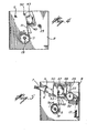
- the timer mechanism illustrated generally at-I, includes a cycle cam 3 and one or more product timer cams 5.
- the cycle cam 3 is a notch cam whereas the product timer cams 5 include raised portions 5a (FIG. 5) and unraised portions.
- each lever arm 7 associated with each product timer cam 5 is a selector lever arm 7. Movement of each lever arm 7, when the timer is in its unactuated position, is prevented by a latch 9 which is mounted on a movable latch rod 11. An end of the latch rod 11 is connected to a plunger 13 of a solenoid 15 for axial movement. As shown in FIGS. 5 and 6, each of the selector lever arms 7 is pivotable about a rod 23 and it is urged into its upper or non-select position (i.e., the position at which none of the secondary product is selected) by a spring 17.
- cams 3, 5 are corotatably mounted for rotation on a common cam axle 19.
- a brake mechanism 21 is provided for holding each of the selector lever arms 7 in a selected position.
- the brake mechanism includes an axially movable support rod 23 slidably mounted on a frame 8, a pair of non-rotatable apertured friction plates 25 secured to the frame 8 and through which the support rod extends, a reaction surface 25a on the frame 8, a pair of hubs 26 secured to the selector lever arms 7 and pivotally supported on the support rod 23, and four friction or rubber rings 27 respectively disposed at opposite ends of said hubs 26 for frictionally acting between an end thereof and one of said friction plates 25 or reaction surface 25a.
- a collar 24 is pinned to the support rod 23 at such point as to provide such axial preload through the friction plates 25, 25, the four friction rings 27, and the hubs 26, 26 against the reaction surface 25a as may be desired in the unactuated position, and so as to transmit the axial braking force from the support rod 23 to the components disposed between the reaction surface 25a and the more remote friction plate 25.
- a pull rod 29 is pivotally connected near one end thereof to an end of the support rod 23. The closer end thereof is adjustably fulcrumed on the frame 8, while the more remote end is reciprocated.
- the pull rod 29 is reciprocated by a pivoting member 31, which pivoting member has one end pivotably connected to the frame 8 at 33 and the other end connected to the plunger 13 of an electric solenoid 15.
- the pivoting member 31 has a roller 35 which engages the free end of the pull rod 29 to force it downwardly as is explained below.
- the pivoting member 31 is a second class lever acting through the roller 35 on the pull rod 29, which in turn is also a second class lever for acting on the brake support rod 23.
- a latch rod spring 37 urges the latch rod 11, and hence the solenoid plunger 13, into its locked or uppermost position (as drawn) as shown in FIG. 1 while a brake rod spring 39 urges the brake support rod 23 into its uppermost position (as drawn).
- a motor 41 is connected to the cam axle 19 through an internal gear train, not shown, to thereby rotate the cams 3 and 5.
- a cycle cam switch 43 having an actuating pin 45 is fixedly secured to the frame 8 and is associated with the cycle cam 3, while a product cam switch 47, having an actuating pin 49, is associated with each product timer cam 5.
- the cycle cam switch 43 has a cam- follower or switch arm 51, and each product cam switch 47 has a cam follower or switch arm 53.
- Each switch 43, 47 can be actuated by movement of the switch arms 51, 53 towards the respective actuating pin 45, 49 so that the switch arm shifts the actuating pin 45, 49.
- Each product cam switch 47 is fixedly secured to a mounting plate 48 pivotally supported on a pin 50 carried on the frame 8, there being a pin-and-slot connection 52 between each selector lever arm 7 and one of the pivotal mounting plates 48.
- the pin-and-slot connection moves the mounting plate 48 to its uppermost position, and hence pivots the switch 47 as far away from the cam 5 as possible.
- the pin-and-slot connection pivots the switch 47 as close to the cam 5 as possible.
- the position of the switch cam thus is shifted over a range with respect to the cam 5 where..it is not actuated to where it is continuously actuated for the duration of the cam cycle.
- FIG. 7 shows a customer panel for the continuously variable selection of a product such as, for example, cream and sugar in a coffee dispensing machine.
- the selector lever arms 7 are each movable in a slot 55.
- the panel is marked or calibrated at the top and at the bottom of each slot to indicate appropriate quantities. In FIG. 7, these markings are illustrated as zero (0) and full (F). Other appropriate markings or calibrations could be selected.
- the timer works as follows: When a coin is placed into a coin mechanism of a dispensing machine, the coin mechanism will actuate the electric solenoid 15 so that the latch rod 11 is moved laterally (appearing downwardly in FIG. 2) to release the selector lever arms 7. Simultaneously the electric solenoid 15 actuates the brake mechanism 21 to maximize the braking force on the lever arms. The customer can now adjust the lever arms to the amount of supplementary product desired in his selected drink. On doing so, the brake mechanism 21 is manually over-ridden and more energy is stored in the springs 17. The brake mechanism 21 will hold each lever arm 7 in the selected position. As shown in FIG.
- the friction or rubber rings 27 are compressed against the hubs 26 of the selector lever arm 7 and the friction surfaces of the friction plates 25-and the reaction surface 25a due to the pulling action of the support rod acting through the collar 24.
- the compressed rubber acting against the sides of the lever arm hubs 26 will brake the selector levers at any selected position.
- the pivot member 31 amplifies the force from the solenoid.
- the solenoid is loaded only to the extent of retaining the movable end of the pivot member 31 in its actuated position rather than having to hold down the support rod 23 against the full force of the spring 39.
- the roller 35 of the pivoting member 31 urges the free end of the rod 29 to the actuated position of FIG. 2 to thereby actuate the brake support rod 23.
- a further customer- actuated signal initiates the dispensing of the main product, which also energizes the motor 41 independently of the switch 43.
- the motor 41 rotates the axle 19 to thereby rotate the cams 3 and 5.
- the cam 3 actuates the switch 43 which is in a holding circuit for the motor 41.
- the cam 3 thus ensures that the motor 41 will remain energized so that cam rotation ceases after a travel of 360°.
- the arm 51 falls into the notch of the cam 3 so that the switch 43 is deactuated to turn off the motor 41.
- the switch 47 is provided for being connected to a secondary product dispensing means such as a product door opener or to a product motor dispenser to actuate the dispensing means by either opening the door or turning on the motor dispenser.
- a secondary product dispensing means such as a product door opener or to a product motor dispenser to actuate the dispensing means by either opening the door or turning on the motor dispenser.
- the switch arm 53 cannot depress the actuating pin 49 even if the free end of the arm 53 were riding on the raised position 5a of the cam 5. Thus no supplementary product can be dispensed.
- the switch arm 53 When the lever arm 7 is in the lowermost position, as shown in FIG. 6, the switch arm 53 will depress the actuating pin 49 continuously for any cam position, i.e. the full cycle of the cam 5.
- the actuating pin 49 will be depressed for a longer time, to provide a longer time period, when the lever arm is in the position shown in solid lines in FIG. 6 than when the lever arm is in the position shown in solid lines in FIG. 5. Accordingly, a greater quantity would be dispensed with the lever arm in the bottom-most position as shown in FIG. 6.
- the amount of the time that the actuating pin will remain depressed is intermediate between the time of FIG. 5 and the time of FIG. 6, that is, the time period and therefore the amount of product dispensed, will be intermediate the time period, and therefore the amount dispensed in the FIG. 5 position and the time period and therefore the amount dispensed in the FIG . 6 position.
- the amount of product dispensed is also continuously variable. Product is dispensed in the time period during which the actuating pin is depressed.
- a source of power illustrated in the drawings as battery 205, is in series with a capacitor 207.
- One output of the rheostat 211 is connected to the other side of the capacitor. The other output of the rheostat is grounded.
- Lead 209 is connected to the dispensing motor or a product door opener to provide a power input for a period of time as determined by the RC constant.
- an LC timing circuit is used. Referring to Fig. 9, slot 201 of inductance 203 is connected to be upwardly and downwardly movable with the pivoting of the lever 7. One output of the inductor is connected to a source of power, illustrated as battery 205. The other output of the inductor is connected to the top end of a capacitor 207. Lead 209 is connected to a product dispensing motor or a product door opener which will be activated for a period dependent on the LC constant which is, in turn, dependent on the position of the lever 7.
- a series of RC circuits having different time constants could be connected through Mylar switches, which would appear on the front face of the dispensing machine, to a source of power.
- a customer would select the amount of product desired by pressing the appropriate Mylar switch which would then activate its associated timing circuit.
- the timing arrangement would activate either a product door opener or a product dispensing motor.
- Sl, S2, S3 ... Sn are Mylar switches which would appear on the face of the machine.
- RC circuits, RlCl, R2C2, R3C3 ... RnCn are arranged so that each one has a different value. Thus, by pressing a different one of the switches, a different time constant is selected.
- FIG. 11 illustrates yet another embodiment for providing a continuously variable quantity of a product from a dispenser.
- 101 comprises a hopper for storing the product.
- the hopper has an output means such as a funnel 103 through which the product from the hopper is dispensed.
- a guide means 105 may guide the product to a container such as a cup 106 or the like.
- the product is dispensed from the hopper 101 by means of a dispensing motor 107.
- the embodiment in F I G . 11 also includes a transmitter 109 for transmitting wave signals, for example, optical, solar or electronic waves.
- Receiver 111 receives the waves after a variable interval as will be explained below, and means 113 calculates the distance the waves have travelled between the transmitter output 110 and the receiver input 112. Such means are well known in the art and require no further description here.
- the calculated distance is then provided, as an analog or digital signal, to a converter 115 which converts the distance to a time.
- the output of 115 is fed to the dispensing motor to turn the motor on for the time as provided at the output of 115.
- the length of the travel path between the output of the transmitter 110 and the input of the receiver 112 is varied.
- the length of the path is varied by a movable means, for example, movable adjustment arm 117.
- the adjustment arm is varied along the scale 119 to provide an indication to the customer of the quantity of the product he has selected.
- the output 110 of the transmitter 109 is directed at the movable arm 117.
- the input 112 of the receiver 111 is also directed at the movable arm 117. Accordingly, signal waves transmitted by the transmitter will propagate to the arm 117 and be bounced off the arm back to the input 112 of the receiver. Moving the movable arm, by pivoting it about the pivot point 118, will change both the distance from the output 110 of the transmitter 109 to the movable arm as well as the distance from the movable arm 117 to the input 112 of the receiver. Accordingly, by pivoting the movable arm, the travel path between the output 110 of the transmitter 109 and the input 112 of the receiver 111 is varied.
- the path length is calculated in the calculator 113 in, for example, the same manner that path length is calculated in a radar system.
- the path length quantity is then transmitted, either as an analog level, or a digitally coded signal, to converter 115 where the quantity is converted to a time period.
- Converter 115 will then turn the dispensing motor on for a period equal to the time period as arrived at in 115, so that the dispensing motor will cause the product to be dispensed from the hooper 101 for this time period.
- the quantity of the product dispensed is similarly adjusted.
- the amount of dispensing time is adjusted.
- the dispensing time is constant for all quantities dispensed.
- the total quantity dispensed is varied by varying the dispensing rate.
- the movable arm 117 includes a lifter portion 121.
- the lifter portion adjusts the level of a movable stopper means 123, which is disposed in front of the opening 104 of the output funnel 103 of hopper 101, by sliding along the ramp portion 124 of the stopper 123.
- the front end of the stopper is biased downwardly by spring 125, and the stopper is pivotable about the point 126 at the other end thereof.
- the dispensing motor or a product door opener will, of course, be activated by insertion of a coin as described in the embodiments illustrated in FIGS. 1 to 7.
Landscapes
- Physics & Mathematics (AREA)
- General Physics & Mathematics (AREA)
- Vending Machines For Individual Products (AREA)
- Refuse Collection And Transfer (AREA)
- Telephone Function (AREA)
- Manipulator (AREA)
- Devices For Dispensing Beverages (AREA)
- Sorting Of Articles (AREA)
- Apparatus For Making Beverages (AREA)
- Beverage Vending Machines With Cups, And Gas Or Electricity Vending Machines (AREA)
Applications Claiming Priority (2)
| Application Number | Priority Date | Filing Date | Title |
|---|---|---|---|
| US41223282A | 1982-08-27 | 1982-08-27 | |
| US412232 | 1989-09-25 |
Publications (2)
| Publication Number | Publication Date |
|---|---|
| EP0104447A2 true EP0104447A2 (fr) | 1984-04-04 |
| EP0104447A3 EP0104447A3 (fr) | 1986-11-12 |
Family
ID=23632155
Family Applications (1)
| Application Number | Title | Priority Date | Filing Date |
|---|---|---|---|
| EP83108382A Withdrawn EP0104447A3 (fr) | 1982-08-27 | 1983-08-25 | Minuterie |
Country Status (6)
| Country | Link |
|---|---|
| EP (1) | EP0104447A3 (fr) |
| JP (1) | JPS5990194A (fr) |
| AU (1) | AU575537B2 (fr) |
| CA (1) | CA1228413A (fr) |
| FI (1) | FI833043L (fr) |
| NO (1) | NO833075L (fr) |
Cited By (13)
| Publication number | Priority date | Publication date | Assignee | Title |
|---|---|---|---|---|
| US5332123A (en) * | 1992-06-22 | 1994-07-26 | The Coca-Cola Company | Device for the measured dispensing of liquids out of a storage container and synchronous mixing with a diluent |
| US7537138B2 (en) | 2005-06-20 | 2009-05-26 | Nestec S.A. | Methods and systems for delivering foamed beverages from liquid concentrates |
| US7757896B2 (en) | 2006-03-06 | 2010-07-20 | The Coca-Cola Company | Beverage dispensing system |
| US7913879B2 (en) | 2006-03-06 | 2011-03-29 | The Coca-Cola Company | Beverage dispensing system |
| US8162176B2 (en) | 2007-09-06 | 2012-04-24 | The Coca-Cola Company | Method and apparatuses for providing a selectable beverage |
| US8251258B2 (en) | 2007-09-06 | 2012-08-28 | The Coca-Cola Company | Systems and methods of selecting and dispensing products |
| US8739840B2 (en) | 2010-04-26 | 2014-06-03 | The Coca-Cola Company | Method for managing orders and dispensing beverages |
| US8757222B2 (en) | 2010-04-26 | 2014-06-24 | The Coca-Cola Company | Vessel activated beverage dispenser |
| US8960500B2 (en) | 2006-03-06 | 2015-02-24 | The Coca-Cola Company | Dispenser for beverages including juices |
| US9415992B2 (en) | 2006-03-06 | 2016-08-16 | The Coca-Cola Company | Dispenser for beverages having a rotary micro-ingredient combination chamber |
| US9821992B2 (en) | 2006-03-06 | 2017-11-21 | The Coca-Cola Company | Juice dispensing system |
| US10280060B2 (en) | 2006-03-06 | 2019-05-07 | The Coca-Cola Company | Dispenser for beverages having an ingredient mixing module |
| US10631560B2 (en) | 2006-03-06 | 2020-04-28 | The Coca-Cola Company | Methods and apparatuses for making compositions comprising an acid and an acid degradable component and/or compositions comprising a plurality of selectable components |
Families Citing this family (1)
| Publication number | Priority date | Publication date | Assignee | Title |
|---|---|---|---|---|
| JPS62260699A (ja) * | 1986-05-02 | 1987-11-12 | 三菱電機株式会社 | 給水量制御装置 |
Family Cites Families (12)
| Publication number | Priority date | Publication date | Assignee | Title |
|---|---|---|---|---|
| CH206673A (de) * | 1938-05-07 | 1939-08-31 | Beier Walter | Einrichtung zur Herstellung einer Milchkaffee-Mischung. |
| GB899732A (en) * | 1957-10-04 | 1962-06-27 | Still & Sons Ltd W M | Improvements in or relating to beverage dispensing apparatus |
| US3160318A (en) * | 1961-04-06 | 1964-12-08 | Northwest Automatic Products C | Variable quantity cream dispenser |
| US3248011A (en) * | 1964-02-19 | 1966-04-26 | Progressive Metal Equipment In | Liquid dispenser with timer control |
| US3335753A (en) * | 1964-03-02 | 1967-08-15 | Kiser Ohlmann Inc | Control valve with adjustable flow rate, especially for dispensing machines |
| US3319830A (en) * | 1965-04-12 | 1967-05-16 | Wallace W Ward | Liquid dispenser |
| US3445039A (en) * | 1966-10-31 | 1969-05-20 | Progressive Metal Equipment In | Liquid dispenser with timer control |
| US3568887A (en) * | 1967-11-13 | 1971-03-09 | Jet Spray Cooler Inc | Hot beverage dispenser |
| BE791541A (fr) * | 1971-11-19 | 1973-03-16 | Marlet Barrera Jose | Machine automatique a faire le cafe |
| US4265371A (en) * | 1978-10-06 | 1981-05-05 | Trafalgar Industries Inc. | Foodstuff vending apparatus employing improved solid-state type control apparatus |
| JPS5657191A (en) * | 1979-10-16 | 1981-05-19 | Nippon Coinco Co Ltd | Controller for vendor |
| ZA812723B (en) * | 1980-06-02 | 1982-05-26 | Jet Spray Corp | Timer with touch control |
-
1983
- 1983-08-25 AU AU18412/83A patent/AU575537B2/en not_active Ceased
- 1983-08-25 EP EP83108382A patent/EP0104447A3/fr not_active Withdrawn
- 1983-08-25 FI FI833043A patent/FI833043L/fi not_active Application Discontinuation
- 1983-08-26 NO NO833075A patent/NO833075L/no unknown
- 1983-08-26 CA CA000435487A patent/CA1228413A/fr not_active Expired
- 1983-08-26 JP JP58156203A patent/JPS5990194A/ja active Pending
Cited By (22)
| Publication number | Priority date | Publication date | Assignee | Title |
|---|---|---|---|---|
| US5332123A (en) * | 1992-06-22 | 1994-07-26 | The Coca-Cola Company | Device for the measured dispensing of liquids out of a storage container and synchronous mixing with a diluent |
| US7537138B2 (en) | 2005-06-20 | 2009-05-26 | Nestec S.A. | Methods and systems for delivering foamed beverages from liquid concentrates |
| US9415992B2 (en) | 2006-03-06 | 2016-08-16 | The Coca-Cola Company | Dispenser for beverages having a rotary micro-ingredient combination chamber |
| US7757896B2 (en) | 2006-03-06 | 2010-07-20 | The Coca-Cola Company | Beverage dispensing system |
| US10631558B2 (en) | 2006-03-06 | 2020-04-28 | The Coca-Cola Company | Methods and apparatuses for making compositions comprising an acid and an acid degradable component and/or compositions comprising a plurality of selectable components |
| US8162181B2 (en) | 2006-03-06 | 2012-04-24 | The Coca-Cola Company | Beverage dispensing system |
| US10631560B2 (en) | 2006-03-06 | 2020-04-28 | The Coca-Cola Company | Methods and apparatuses for making compositions comprising an acid and an acid degradable component and/or compositions comprising a plurality of selectable components |
| US10280060B2 (en) | 2006-03-06 | 2019-05-07 | The Coca-Cola Company | Dispenser for beverages having an ingredient mixing module |
| US8453879B2 (en) | 2006-03-06 | 2013-06-04 | The Coca-Cola Company | Beverage dispensing system |
| US10029904B2 (en) | 2006-03-06 | 2018-07-24 | The Coca-Cola Company | Beverage dispensing system |
| US9821992B2 (en) | 2006-03-06 | 2017-11-21 | The Coca-Cola Company | Juice dispensing system |
| US8807393B2 (en) | 2006-03-06 | 2014-08-19 | The Coca-Cola Company | Beverage dispensing system |
| US7913879B2 (en) | 2006-03-06 | 2011-03-29 | The Coca-Cola Company | Beverage dispensing system |
| US8960500B2 (en) | 2006-03-06 | 2015-02-24 | The Coca-Cola Company | Dispenser for beverages including juices |
| US8851329B2 (en) | 2007-09-06 | 2014-10-07 | The Coca-Cola Company | Systems and methods of selecting and dispensing products |
| US8814000B2 (en) | 2007-09-06 | 2014-08-26 | The Coca-Cola Company | Method and apparatuses for providing a selectable beverage |
| US10046959B2 (en) | 2007-09-06 | 2018-08-14 | The Coca-Cola Company | Method and apparatuses for providing a selectable beverage |
| US8434642B2 (en) | 2007-09-06 | 2013-05-07 | The Coca-Cola Company | Method and apparatus for providing a selectable beverage |
| US8251258B2 (en) | 2007-09-06 | 2012-08-28 | The Coca-Cola Company | Systems and methods of selecting and dispensing products |
| US8162176B2 (en) | 2007-09-06 | 2012-04-24 | The Coca-Cola Company | Method and apparatuses for providing a selectable beverage |
| US8757222B2 (en) | 2010-04-26 | 2014-06-24 | The Coca-Cola Company | Vessel activated beverage dispenser |
| US8739840B2 (en) | 2010-04-26 | 2014-06-03 | The Coca-Cola Company | Method for managing orders and dispensing beverages |
Also Published As
| Publication number | Publication date |
|---|---|
| CA1228413A (fr) | 1987-10-20 |
| JPS5990194A (ja) | 1984-05-24 |
| FI833043A0 (fi) | 1983-08-25 |
| FI833043A7 (fi) | 1984-02-28 |
| AU1841283A (en) | 1984-03-01 |
| FI833043L (fi) | 1984-02-28 |
| EP0104447A3 (fr) | 1986-11-12 |
| NO833075L (no) | 1984-02-28 |
| AU575537B2 (en) | 1988-08-04 |
Similar Documents
| Publication | Publication Date | Title |
|---|---|---|
| EP0104447A2 (fr) | Minuterie | |
| US4736875A (en) | Timing mechanism | |
| EP2509476B1 (fr) | Dispositif de dosage de café moulu et machine comprenant un tel dispositif | |
| US5027284A (en) | Auto-set drink dispenser | |
| EP2314188B1 (fr) | Appareil et procédé pour remplir des supports de filtres d'une machine à café expresso avec des doses sélectionnées de café moulu à commander | |
| AU627026B2 (en) | Lid dispenser for an automated drinkmaker system | |
| CA2143799C (fr) | Machine a mouler etalonnable et a minuterie | |
| US9541438B2 (en) | Precision seasoner | |
| US4402426A (en) | Weighing and dispensing unit | |
| US5018614A (en) | Ticket vending machine | |
| CA2313608A1 (fr) | Methode et dispositif de dosage du melange de boissons | |
| WO1999030600A1 (fr) | Machine pour preparer des boissons chaudes | |
| GB2233638A (en) | Dispensing cups from stacks. | |
| US4713526A (en) | Reservoir filling arrangement for a coffee machine | |
| US3506156A (en) | Cup dropper with automatic control of replacement stack | |
| EP1586254B1 (fr) | Distributeur de sucre et de bâtonnets mélangeurs | |
| US20230381037A1 (en) | Time delay product dispenser | |
| CN221040122U (zh) | 自动售货机的自助饮料制备系统 | |
| JP2001046231A (ja) | コーヒー飲料の製造装置 | |
| US2057376A (en) | Regulating device for wireless receivers | |
| GB2258216A (en) | Programmable portion control for drink dispenser. | |
| EP0016453A3 (en) | Coin-counting mechanism for a vending machine | |
| GB2077707A (en) | Improved turret cup supply and delivery apparatus | |
| US2063108A (en) | Vending machine and control mechanism therefor | |
| US3610388A (en) | Two-price two-level beverage merchandising machine |
Legal Events
| Date | Code | Title | Description |
|---|---|---|---|
| PUAI | Public reference made under article 153(3) epc to a published international application that has entered the european phase |
Free format text: ORIGINAL CODE: 0009012 |
|
| AK | Designated contracting states |
Designated state(s): AT BE CH DE FR GB IT LI LU NL SE |
|
| PUAL | Search report despatched |
Free format text: ORIGINAL CODE: 0009013 |
|
| AK | Designated contracting states |
Kind code of ref document: A3 Designated state(s): AT BE CH DE FR GB IT LI LU NL SE |
|
| 17P | Request for examination filed |
Effective date: 19870512 |
|
| 17Q | First examination report despatched |
Effective date: 19871111 |
|
| STAA | Information on the status of an ep patent application or granted ep patent |
Free format text: STATUS: THE APPLICATION IS DEEMED TO BE WITHDRAWN |
|
| 18D | Application deemed to be withdrawn |
Effective date: 19890530 |