EP0104592A2 - Dispositif et procédé pour la démonstration des ondes de surface - Google Patents
Dispositif et procédé pour la démonstration des ondes de surface Download PDFInfo
- Publication number
- EP0104592A2 EP0104592A2 EP83109340A EP83109340A EP0104592A2 EP 0104592 A2 EP0104592 A2 EP 0104592A2 EP 83109340 A EP83109340 A EP 83109340A EP 83109340 A EP83109340 A EP 83109340A EP 0104592 A2 EP0104592 A2 EP 0104592A2
- Authority
- EP
- European Patent Office
- Prior art keywords
- surface waves
- saw
- lock
- amplifier
- liv
- Prior art date
- Legal status (The legal status is an assumption and is not a legal conclusion. Google has not performed a legal analysis and makes no representation as to the accuracy of the status listed.)
- Granted
Links
- 238000000034 method Methods 0.000 title claims description 16
- 239000000523 sample Substances 0.000 claims description 17
- 238000001514 detection method Methods 0.000 claims description 8
- 230000000007 visual effect Effects 0.000 abstract 3
- 238000009877 rendering Methods 0.000 abstract 1
- 230000001960 triggered effect Effects 0.000 abstract 1
- 238000010894 electron beam technology Methods 0.000 description 7
- 230000010355 oscillation Effects 0.000 description 3
- 238000005070 sampling Methods 0.000 description 3
- 230000035945 sensitivity Effects 0.000 description 3
- 238000005259 measurement Methods 0.000 description 2
- 230000000737 periodic effect Effects 0.000 description 2
- 230000001133 acceleration Effects 0.000 description 1
- 230000003321 amplification Effects 0.000 description 1
- 239000013078 crystal Substances 0.000 description 1
- 238000003199 nucleic acid amplification method Methods 0.000 description 1
- 238000004626 scanning electron microscopy Methods 0.000 description 1
Images
Classifications
-
- G—PHYSICS
- G01—MEASURING; TESTING
- G01H—MEASUREMENT OF MECHANICAL VIBRATIONS OR ULTRASONIC, SONIC OR INFRASONIC WAVES
- G01H9/00—Measuring mechanical vibrations or ultrasonic, sonic or infrasonic waves by using radiation-sensitive means, e.g. optical means
Definitions
- the invention relates to a device for the detection of surface waves with a corpuscular probe according to the preamble of claim 1 and a corresponding method.
- Running surface waves should be made visible with a corpuscular beam.
- the invention is based on the object of specifying a device of the type mentioned at the outset and a corresponding method which, compared to the known sampling method, allow the detection sensitivity to be improved by a few orders of magnitude.
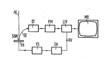
- the figure schematically shows a device according to the invention for visualizing surface waves.
- a device for visualizing surface waves SAW according to the invention is shown in the figure.
- a frequency synthesizer SH generates an arbitrarily selectable oscillation, with which both the sample PR is excited to form surface waves SAW and the lock-in amplifier LIV is controlled.
- a frequency synthesizer SH is a circuit arrangement for generating almost harmonic-free vibrations with a very high frequency constancy.
- a frequency synthesizer SH derives the synthesized frequencies by multiplication or by division from the frequency of a normal frequency generator.
- a frequency synthesizer SH is used e.g. for measuring purposes or for controlling transmitters whose frequency has to be changed frequently.
- the oscillation transmitted from the frequency synthesizer SH to the sample PR is amplified in the meantime by an amplifier VS.
- the oscillation generated by the frequency synthesizer SH is transmitted to the lock-in amplifier LIV via the input RV on the lock-in amplifier LIV for the reference voltage.
- Surface waves SAW can be caused on the sample PR by finger transducers, for example, which move from the fre sequence synthesizer SH can be controlled.
- the continuously switched on primary electron beam PE scans a part of the surface of the sample PR and thereby triggers secondary electrons SE on the sample PR.
- the number of secondary electrons SE detected at the detector DT varies according to the method of potential contrast with the potential at the respective measuring point to which the primary electron beam PE is directed.
- the secondary electrons SE trigger a secondary electron signal in the detector DT via a scintillator.
- This secondary electron signal is further processed in a photomultiplier PM and then amplified. After amplification of the secondary electron signal in the fast scintillator-photomultiplier combination according to the figure, the signal fluctuations in the secondary electron signal caused by surface waves SAW are detected with the lock-in amplifier LIV.
- Such a method according to the invention allows an improvement in the detection sensitivity of signal fluctuations in the secondary electron signal by orders of magnitude compared to the sampling method known from the above-mentioned literature reference.
- the measurement signal detected in the lock-in amplifier LIV can, for example, be made visible on a monitor MO depending on the position of the primary electron beam PE on the sample PR.
- a potential contrast image of the signal fluctuations in the secondary electron signal which have been caused by surface waves SAW, is then obtained on the screen of the monitor MO.
- the respective surface waves SAW can then be made visible via such a potential contrast image on the monitor MO.
- an Ithaco Dynatrac model 391A can be used as a lock-in amplifier.
- the lock-in amplifier LIV only makes those parts of the measurement signal visible on the screen of the monitor MO which have the same frequency as the surface waves SAW excited on a suitable, for example piezoelectric, surface of the sample PR, because exactly the same vibration with which the surface waves SAW are excited on the sample PR, is also applied to the reference voltage input RV of the lock-in amplifier LIV.
- a method according to the invention does not require a pulsed beam blanking system, for example.
- the lock-in amplifier LIV shows on monitor MO the amplitude of that signal component in the secondary electron signal which has exactly the same frequency as the surface waves SAW.
- the monitor MO does not show a phase of periodic processes, but rather the amplitude as a function of the rastered measuring points on the surface of the sample PR is made visible, which belonged to the signal component of the secondary electron signal, which has exactly the same frequency as the SAW surface waves. Fluctuations within this amplitude as a function of the scanned measuring points on the surface of the sample PR can be determined with a very high detection sensitivity using a method according to the invention.
- the primary electron beam PE can be accelerated with 2.5 kV, for example. At this acceleration voltage, insulating crystals in which surface waves SAW can be excited are not charged the.
- the primary electron beam PE can have a diameter of 1.2 / .mu.m, with which a beam current of 10 -7 A is achieved.
Landscapes
- Physics & Mathematics (AREA)
- General Physics & Mathematics (AREA)
- Analysing Materials By The Use Of Radiation (AREA)
- Investigating Or Analyzing Materials By The Use Of Ultrasonic Waves (AREA)
- Measurement Of Mechanical Vibrations Or Ultrasonic Waves (AREA)
Applications Claiming Priority (2)
| Application Number | Priority Date | Filing Date | Title |
|---|---|---|---|
| DE19823235699 DE3235699A1 (de) | 1982-09-27 | 1982-09-27 | Vorrichtung und verfahren zum nachweis von oberflaechenwellen |
| DE3235699 | 1982-09-27 |
Publications (3)
| Publication Number | Publication Date |
|---|---|
| EP0104592A2 true EP0104592A2 (fr) | 1984-04-04 |
| EP0104592A3 EP0104592A3 (en) | 1984-10-03 |
| EP0104592B1 EP0104592B1 (fr) | 1988-05-04 |
Family
ID=6174248
Family Applications (1)
| Application Number | Title | Priority Date | Filing Date |
|---|---|---|---|
| EP83109340A Expired EP0104592B1 (fr) | 1982-09-27 | 1983-09-20 | Dispositif et procédé pour la démonstration des ondes de surface |
Country Status (3)
| Country | Link |
|---|---|
| EP (1) | EP0104592B1 (fr) |
| JP (1) | JPS5979850A (fr) |
| DE (2) | DE3235699A1 (fr) |
Cited By (1)
| Publication number | Priority date | Publication date | Assignee | Title |
|---|---|---|---|---|
| DE4428519A1 (de) * | 1994-08-11 | 1996-02-15 | Paul Drude Inst Fuer Festkoerp | Verfahren und Vorrichtung zur Messung akustischer Scherschwingungen und Scherwellenfelder an Festkörperoberflächen |
Family Cites Families (2)
| Publication number | Priority date | Publication date | Assignee | Title |
|---|---|---|---|---|
| FR2120338A5 (fr) * | 1970-12-30 | 1972-08-18 | Thomson Csf | |
| DE3036713A1 (de) * | 1980-09-29 | 1982-05-13 | Siemens AG, 1000 Berlin und 8000 München | Verfahren und anordnung zur quantitativen potentialmessung an oberflaechenwellenfiltern |
-
1982
- 1982-09-27 DE DE19823235699 patent/DE3235699A1/de not_active Withdrawn
-
1983
- 1983-09-20 DE DE8383109340T patent/DE3376505D1/de not_active Expired
- 1983-09-20 EP EP83109340A patent/EP0104592B1/fr not_active Expired
- 1983-09-22 JP JP58176135A patent/JPS5979850A/ja active Pending
Non-Patent Citations (3)
| Title |
|---|
| ELECTRONICS INTERNATIONAL, Band 53, Nr. 19, August 1980, Seiten 73-74, New York; USA; J. GOSCH: " E beam makes surface acoustic waves visible" * |
| ELECTRONICS INTERNATIONAL, Band 56, Nr. 10, Mai 1983, Seiten 132-136, New York, USA; H.-P. FEUERBAUM et al.: "Scanned electron-beam probe shows surface acoustic waves in action" * |
| INSTRUMENTS AND EXPERIMENTAL TECHNIQUES, Band 24, Nr. 4, Teil 2, Juli/August 1981, Seiten 1049-1050, New York, USA; R.YU. VALATKA et al.: "Application of a scanning electron microscope for the investigation of surface-acoustic-wave propagation" * |
Cited By (1)
| Publication number | Priority date | Publication date | Assignee | Title |
|---|---|---|---|---|
| DE4428519A1 (de) * | 1994-08-11 | 1996-02-15 | Paul Drude Inst Fuer Festkoerp | Verfahren und Vorrichtung zur Messung akustischer Scherschwingungen und Scherwellenfelder an Festkörperoberflächen |
Also Published As
| Publication number | Publication date |
|---|---|
| JPS5979850A (ja) | 1984-05-09 |
| EP0104592A3 (en) | 1984-10-03 |
| EP0104592B1 (fr) | 1988-05-04 |
| DE3376505D1 (en) | 1988-06-09 |
| DE3235699A1 (de) | 1984-03-29 |
Similar Documents
| Publication | Publication Date | Title |
|---|---|---|
| DE2813947C2 (de) | Verfahren zur berührungslosen Messung des Potentialverlaufs in einem elektronischen Bauelement und Anordnung zur Durchführung des Verfahrens | |
| EP0428663B1 (fr) | Procede et dispositif d'analyse spectrale rapide de signaux en un ou plusieurs points de mesure | |
| EP0166814B1 (fr) | Méthode et dispositif pour détecter et afficher un point de mesure conduisant une tension d'au moins une certaine fréquence | |
| EP0048857B1 (fr) | Dispositif stroboscopique de détermination d'un potentiel utilisant un appareil de mesure de faisceaux électroniques et méthode de fonctionnement d'un tel dispositif | |
| CH634922A5 (de) | Einrichtung zum messen der akustischen eigenschaften und deren aenderungen einer probe. | |
| DE69721506T2 (de) | Betriebsverfahren für eine ionenfalle | |
| DE2743200A1 (de) | Verbesserung an einer vorrichtung zur elektronenstrahleintastung | |
| DE1589906B2 (de) | Rasterelektronenmikroskop | |
| DE3036708A1 (de) | Elektronenstrahl-messgeraet zur stroboskopischen messung hochfrequenter periodischer vorgaenge | |
| EP0104592B1 (fr) | Dispositif et procédé pour la démonstration des ondes de surface | |
| EP0166815A1 (fr) | Méthode et dispositif pour l'analyse spectrale d'un signal en un point de mesure | |
| EP0196531B1 (fr) | Procédé pour déterminer indirectement la distribution de l'intensité d'impulsions de faisceaux de particules créés dans un appareil de mesure à faisceau de particules | |
| DE1201086B (de) | Verfahren und Vorrichtung zur Kompensation veraenderlicher Pruefbedingungen bei der Ultraschall-Werkstoffpruefung | |
| EP0226913A2 (fr) | Procédé et dispositif pour localiser et/ou afficher des points d'un échantillon conduisant un signal caractéristique dépendant du temps | |
| EP0136591B1 (fr) | Procédé pour mesurer les courbes des signaux à basses fréquences à l'intérieur des circuits intégrés avec une sonde à électrons | |
| EP0302241B1 (fr) | Mesure de tension avec une sonde à électrons sans signal de déclenchement externe | |
| EP0048863B1 (fr) | Méthode et dispositif de mesure quantitatif du potentiel d'un filtre d'ondes de surface | |
| EP0308678A1 (fr) | Procédé et appareil de mesure des phases des signaux à un point de mesure à l'aide d'un rayon non-modulé de particules | |
| EP4650795A1 (fr) | Circuit de commande d'un dispositif de mesure de champ, procédé de commande du dispositif de mesure de champ et dispositif de mesure de champ | |
| DE3519401A1 (de) | Verfahren und vorrichtung zur detektion und abbildung eines punktes einer probe, der ein signal wenigstens einer bestimmten frequenz fuehrt | |
| EP0105403B1 (fr) | Dispositif et procédé pour la mesure directe des variations de signal en plusieurs points avec une haute résolution de temps | |
| EP0002451A1 (fr) | Procédé et dispositif pour la mesure sans contact d'impuretés dans les semi-conducteurs | |
| DE19546879A1 (de) | Verfahren zur Charakterisierung von elektrisch leitfähigen Festkörperoberflächen | |
| DE1259407B (de) | Verfahren zur Erzeugung von elektrischen Schwingungen, deren Frequenz von einer Gleichspannung und dem Verhaeltnis von Ladung zu Masse von Gasionen abhaengt, Verfahren zur Messung des Verhaeltnisses von Ladung und Masse von Gasionen und Verfahren zur Frequenzmodulation unter Verwendung des erstgenannten Verfahrens | |
| DE2901939A1 (de) | Verfahren und schaltungsanordnung fuer die spannungskontrastabtastung eines prueflings mit einem elektronenmikroskop |
Legal Events
| Date | Code | Title | Description |
|---|---|---|---|
| PUAI | Public reference made under article 153(3) epc to a published international application that has entered the european phase |
Free format text: ORIGINAL CODE: 0009012 |
|
| AK | Designated contracting states |
Designated state(s): DE GB NL |
|
| PUAL | Search report despatched |
Free format text: ORIGINAL CODE: 0009013 |
|
| AK | Designated contracting states |
Designated state(s): DE GB NL |
|
| 17P | Request for examination filed |
Effective date: 19850328 |
|
| 17Q | First examination report despatched |
Effective date: 19860807 |
|
| R17C | First examination report despatched (corrected) |
Effective date: 19870227 |
|
| GRAA | (expected) grant |
Free format text: ORIGINAL CODE: 0009210 |
|
| AK | Designated contracting states |
Kind code of ref document: B1 Designated state(s): DE GB NL |
|
| GBT | Gb: translation of ep patent filed (gb section 77(6)(a)/1977) | ||
| REF | Corresponds to: |
Ref document number: 3376505 Country of ref document: DE Date of ref document: 19880609 |
|
| PLBE | No opposition filed within time limit |
Free format text: ORIGINAL CODE: 0009261 |
|
| STAA | Information on the status of an ep patent application or granted ep patent |
Free format text: STATUS: NO OPPOSITION FILED WITHIN TIME LIMIT |
|
| 26N | No opposition filed | ||
| PG25 | Lapsed in a contracting state [announced via postgrant information from national office to epo] |
Ref country code: GB Effective date: 19890920 |
|
| PG25 | Lapsed in a contracting state [announced via postgrant information from national office to epo] |
Ref country code: NL Effective date: 19900401 |
|
| GBPC | Gb: european patent ceased through non-payment of renewal fee | ||
| NLV4 | Nl: lapsed or anulled due to non-payment of the annual fee | ||
| PG25 | Lapsed in a contracting state [announced via postgrant information from national office to epo] |
Ref country code: DE Effective date: 19900601 |