EP0104597A2 - Corps isolant, en particulier corps façonné, à base de fibres minérales et d'un liant et élément en forme de pot, matière composite et coquille isolante en dérivant - Google Patents
Corps isolant, en particulier corps façonné, à base de fibres minérales et d'un liant et élément en forme de pot, matière composite et coquille isolante en dérivant Download PDFInfo
- Publication number
- EP0104597A2 EP0104597A2 EP83109366A EP83109366A EP0104597A2 EP 0104597 A2 EP0104597 A2 EP 0104597A2 EP 83109366 A EP83109366 A EP 83109366A EP 83109366 A EP83109366 A EP 83109366A EP 0104597 A2 EP0104597 A2 EP 0104597A2
- Authority
- EP
- European Patent Office
- Prior art keywords
- mineral fiber
- incision
- shell
- component
- recess
- Prior art date
- Legal status (The legal status is an assumption and is not a legal conclusion. Google has not performed a legal analysis and makes no representation as to the accuracy of the status listed.)
- Withdrawn
Links
Images




Classifications
-
- F—MECHANICAL ENGINEERING; LIGHTING; HEATING; WEAPONS; BLASTING
- F16—ENGINEERING ELEMENTS AND UNITS; GENERAL MEASURES FOR PRODUCING AND MAINTAINING EFFECTIVE FUNCTIONING OF MACHINES OR INSTALLATIONS; THERMAL INSULATION IN GENERAL
- F16L—PIPES; JOINTS OR FITTINGS FOR PIPES; SUPPORTS FOR PIPES, CABLES OR PROTECTIVE TUBING; MEANS FOR THERMAL INSULATION IN GENERAL
- F16L59/00—Thermal insulation in general
- F16L59/02—Shape or form of insulating materials, with or without coverings integral with the insulating materials
- F16L59/021—Shape or form of insulating materials, with or without coverings integral with the insulating materials comprising a single piece or sleeve, e.g. split sleeves; consisting of two half sleeves; comprising more than two segments
- F16L59/022—Shape or form of insulating materials, with or without coverings integral with the insulating materials comprising a single piece or sleeve, e.g. split sleeves; consisting of two half sleeves; comprising more than two segments with a single slit
- F16L59/023—Shape or form of insulating materials, with or without coverings integral with the insulating materials comprising a single piece or sleeve, e.g. split sleeves; consisting of two half sleeves; comprising more than two segments with a single slit with a hinge opposite the slit
-
- B—PERFORMING OPERATIONS; TRANSPORTING
- B29—WORKING OF PLASTICS; WORKING OF SUBSTANCES IN A PLASTIC STATE IN GENERAL
- B29C—SHAPING OR JOINING OF PLASTICS; SHAPING OF MATERIAL IN A PLASTIC STATE, NOT OTHERWISE PROVIDED FOR; AFTER-TREATMENT OF THE SHAPED PRODUCTS, e.g. REPAIRING
- B29C69/00—Combinations of shaping techniques not provided for in a single one of main groups B29C39/00 - B29C67/00, e.g. associations of moulding and joining techniques; Apparatus therefore
-
- B—PERFORMING OPERATIONS; TRANSPORTING
- B29—WORKING OF PLASTICS; WORKING OF SUBSTANCES IN A PLASTIC STATE IN GENERAL
- B29C—SHAPING OR JOINING OF PLASTICS; SHAPING OF MATERIAL IN A PLASTIC STATE, NOT OTHERWISE PROVIDED FOR; AFTER-TREATMENT OF THE SHAPED PRODUCTS, e.g. REPAIRING
- B29C48/00—Extrusion moulding, i.e. expressing the moulding material through a die or nozzle which imparts the desired form; Apparatus therefor
- B29C48/03—Extrusion moulding, i.e. expressing the moulding material through a die or nozzle which imparts the desired form; Apparatus therefor characterised by the shape of the extruded material at extrusion
- B29C48/09—Articles with cross-sections having partially or fully enclosed cavities, e.g. pipes or channels
-
- B—PERFORMING OPERATIONS; TRANSPORTING
- B29—WORKING OF PLASTICS; WORKING OF SUBSTANCES IN A PLASTIC STATE IN GENERAL
- B29C—SHAPING OR JOINING OF PLASTICS; SHAPING OF MATERIAL IN A PLASTIC STATE, NOT OTHERWISE PROVIDED FOR; AFTER-TREATMENT OF THE SHAPED PRODUCTS, e.g. REPAIRING
- B29C48/00—Extrusion moulding, i.e. expressing the moulding material through a die or nozzle which imparts the desired form; Apparatus therefor
- B29C48/03—Extrusion moulding, i.e. expressing the moulding material through a die or nozzle which imparts the desired form; Apparatus therefor characterised by the shape of the extruded material at extrusion
- B29C48/12—Articles with an irregular circumference when viewed in cross-section, e.g. window profiles
-
- B—PERFORMING OPERATIONS; TRANSPORTING
- B29—WORKING OF PLASTICS; WORKING OF SUBSTANCES IN A PLASTIC STATE IN GENERAL
- B29C—SHAPING OR JOINING OF PLASTICS; SHAPING OF MATERIAL IN A PLASTIC STATE, NOT OTHERWISE PROVIDED FOR; AFTER-TREATMENT OF THE SHAPED PRODUCTS, e.g. REPAIRING
- B29C48/00—Extrusion moulding, i.e. expressing the moulding material through a die or nozzle which imparts the desired form; Apparatus therefor
- B29C48/03—Extrusion moulding, i.e. expressing the moulding material through a die or nozzle which imparts the desired form; Apparatus therefor characterised by the shape of the extruded material at extrusion
- B29C48/13—Articles with a cross-section varying in the longitudinal direction, e.g. corrugated pipes
Definitions
- the invention relates to a mineral fiber insulating body, in particular a molded part, made of mineral fibers bound with binder in felt or plate consistency or in shell form, according to the preamble of claim 1, as well as products produced herewith or here in the form of a pot-shaped part according to the preamble of claim 5, one Composite component according to the preamble of claim 7 and a mineral fiber insulation shell according to the preamble of claim 9.
- Mineral fiber products for sound and / or thermal insulation are mainly manufactured as sheets, plates or shells. These products are also well suited for many areas of application, since they may only need to be cut to size. However, if uneven surfaces or complicated bodies are to be insulated with this, considerable effort may be required to adapt these products to the desired shape.
- multi-layer insulation layers are therefore often used in order to obtain corresponding overlaps at joint points, or a step fold is introduced into a single-layer insulation layer by milling, for example. Moldings are often required chen, which are produced as stampings and require such considerable mold costs - for complicated body and F LAE.
- the invention has for its object a thermal insulation body of the type specified in the preamble of claim 1 and special, hereby or hereby manufactured products according to the preamble of To create claims 5, 7 and 9, in which an adaptation to the dimensions and shapes of surfaces or bodies to be insulated in individual cases can be done easily and without material loss for many applications.
- the material area intended for the formation of the recess is thus delimited from the surrounding material by one or more incisions and, if necessary, its compressibility is improved and the depth of the intended recess is separated, so that the material separated in this way in the area of the intended recess for its formation can be easily compressed. Only relatively small forces are required for this, depending on the consistency of the mineral fiber material, of course, since the deforming action is actually limited to the limited area of the depression due to the incision limitation and, if necessary, is facilitated by additional internal incisions, particularly in the case of large depressions in shell surfaces.
- the incision limitation of the depression prevents deforming entrainment of surrounding material areas.
- Such surrounding material areas can, however, be deformed separately, if necessary, to different extents, whereby interactions due to the incision boundaries between the individual material areas are excluded.
- the mineral fiber material is then compressed in relation to the starting material, which is the case for certain users cases is advantageous.
- the compressed mineral fiber material tends to spring back at the bottom of the depression, which is also frequently desired, for example in order to achieve a tight fit even if the dimensions are inaccurate.
- the incision advantageously extends transversely to the main orientation direction of the fibers. It is thereby achieved that the compression of the mineral fiber material takes place predominantly by mutual proximity of adjacent fibers and only to a lesser extent by kink loading and thus breakage of fibers lying in the loading direction. Since such mineral fiber products generally have fibers oriented parallel to the surface, the implementation of this measure generally does not pose any additional problems if the incision runs vertically into the material from the surface, which in turn is the rule for most applications.
- the incision is preferably made in relation to the depth of the one to be produced. Deepening led to greater depth. In this way, on the one hand, the production of a deepening of the bearing of variable depth depending on the circumstances of the individual case is made possible without any problems, since even in cases of somewhat greater depth there is no fear of the compression movement being impeded by the holding effect of adjacent, non-separated material parts.
- the incisions can easily be made mechanically in the course of production or in the course of subsequent assembly, taking into account the circumstances of the individual case, for example by hand with a knife.
- a mineral fiber insulation body provided by the manufacturer with an incision is functionally fully operational even if no indentation is actually created at the incision, since the incisions can be kept extremely narrow, barely visible and there is no removal of mineral fiber material at this point with their introduction.
- This additional advantage of the invention compared to milling out or the like can in particular also be used according to claim 4 to make a plurality or a plurality of incisions at the manufacturer's sites where there is only one possibility for a later need to form a recess.
- the incisions can be made according to a certain pattern, for example in parallel rows or in a rectangular pattern, and, in use, those fields between the incisions can be selectively deformed by compression to form a depression, where this is necessary, while other fields despite the cuts of deformations present there remain unaffected.
- the types can be limited to a certain specific pattern, certain incision distances or certain grating widths or the like in the case of stockpiling, and for the variable application in each case it is only selected which of the prefabricated patterns best meets the needs of the application.
- the subclaims 6, 8 and 10 have advantageous developments of the pot-shaped part according to claim 5 or the composite component according to claim 7 or the thermal insulation shell according to claim 9.
- a mineral fiber insulation body designated by 1 according to FIG. 1 may be present in the example in the consistency of a relatively dimensionally stable plate.
- the mineral fiber insulation body 1 is intended to accommodate a component 2 in the installation position in the form of a threshold in a recess 3 in the example case.
- the threshold is provided on one of the two rigid boundary walls labeled 4 and 5, between which the mineral fiber insulating body 1 is to be inserted.
- an incision 6 and 6a is made in the surface of the insulating body 1 in the edge region of the recess 3, which can be done either by punching during the course of manufacture or assembly, or subsequently, if necessary, using a suitable cutting tool such as a knife or a fox tail .
- a suitable cutting tool such as a knife or a fox tail .
- the mineral fiber material is compressed on the front side of the component 2 between the incisions 6 and 6a when the insulating body 1 is installed between the rigid boundary walls 4 and 5, so that the component 2 forms the recess 3 can penetrate the mineral fiber material.
- the cuts 6 and 6a on both sides prevent any interference with the adjacent material.
- the mineral fiber material in the base of the recess 3 only provides limited resistance to the penetration of the component 2, since it can move independently of the mineral fibers that are adjacent on the side.
- the cuts 6 and 6a are made at a depth T exceeding the depth t of the recess 3, the cuts 6 and 6a extend into a material region at a distance from the bottom of the recess 3, in which the compression is only slightly effective , so that the lateral connection there to the surrounding mineral fibers is harmless as a result of the felting and the binder present. Since the mineral fiber material tries to spring back in the base of the recess 3, the insulating body 1 is at the same time pressed against the opposite boundary wall 5 with a predetermined pressure.
- the mineral fiber insulation body 1 In the event that the mineral fiber insulating body 1 is already prepared for receiving the component 2 by making the incisions 6 and 6a, but the component 2 is actually not present at the installation position in an individual case, there are no functional disadvantages; because then the mineral fiber insulation body 1 lies in the configuration shown in FIG. 1 between the boundary walls 4 and 5 and is thus available over its entire surface without loss of insulation capacity Available. Even when the mineral fiber material is compressed by the component 2 with the formation of a corresponding recess 3, the thermal or acoustic insulation capacity of the mineral fiber material in the region of the component 2 does not suffer, or does not suffer appreciably, since no material loss is associated with the formation of the recess.
- Panel or sheet-shaped mineral fiber insulation bodies 1 made of mineral fibers bound with binder are generally produced on continuous production lines in such a way that the mineral fibers are deposited on the web after they have been produced and then subjected to further effects such as compaction, heating, cuts, etc. at work stations passed through by the web .
- a main orientation of the fibers is established, which is essentially parallel to the support surface of the production line and to a certain extent also in the direction of production, so that the fibers are to a large extent approximately parallel to the surface.
- FIG. 5 illustrate a special application of the invention for producing a composite component 10, as is used, for example, for the thermal insulation of heat storage devices.
- the composite component according to the invention illustrated in FIG. 5 consists of two plate-shaped mineral fiber insulating bodies 11 and 11a, one of which is not shown in greater detail on both sides provided heat storage and are connected on the end face by a component 12, which in turn is a mineral fiber insulation body.
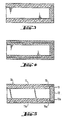
- FIGS. 3 and 4 A problem here is that in order to achieve the required tightness in the dimensional tolerances of the mineral fiber plates occurring in the connection areas, a stepped rabbet connection must be used. This can, of course, be produced in the manner shown in FIG. 3 simply by providing the side edges of the mineral fiber boards which abut one another, as is also known for other materials in such a joint area, for example by milling with steps. In order to avoid such processing, the solution shown in FIG. 4 is then adopted, in which the individual insulation layers are designed in two layers, and a step-like configuration is achieved without milling or the like by corresponding mutual arrangement of the individual layers shown in FIG. 4.
- the described problem within the scope of the invention can be easily solved by making incisions 16 and 16a in the mineral fiber insulating bodies 11 and 11a in the manner shown in Fig. 5, in which the thermal insulation material there Formation of wells 13 and 13a is compressible without disturbing adjacent material parts.
- the component 12 in the form of the end plate is then simply inserted between the recesses 13 and 13a formed in this way by a suitable tool and resiliently clamped in the region of the recesses 13 and 13a to form a defined step fold when the compressed material springs back.
- the mineral fiber plates for forming the mineral fiber insulating bodies 11 and 11a and the component 12 can have the usual thickness and constant formats; it is only necessary to make the incisions 16 and 16a according to the principles explained in connection with FIGS. 1 and 2 in order to obtain a composite component 10 according to the invention.
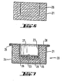
- FIG. 6 and 7 illustrate the formation of a cup-shaped part 20 as a further application of the invention, as can be seen particularly from FIG. 7.
- a mineral fiber insulating body 21 is first made available, into which an annular incision 26 is made, as can be seen from FIG. 6.
- the thermal insulation body 21 is then inserted in the example in a housing 24 which covers the outside of the pot-shaped part 20 and ends in the upper edge flanges 25 in the example.
- a shell corresponding to the contour of the pot recess 27 with an outer diameter corresponding approximately to the diameter of the annular incision 26 is raised from above and pressed into the mineral fiber insulating body 21 with compression of the mineral fiber material in the area within the annular incision 26, so that a recess 23 is formed.
- the annular surface outside of the annular incision 26 is covered by an upper ring flange 28 of the shell-shaped component 22, so that the component 22 can be attached to the housing 24 or to the flange 25 thereof, the housing 24 thus serving as a counter-holder for the component 22.
- an electrical heating winding 29 is arranged on the bottom of the shell-shaped component 22, which can serve for heating a medium to be arranged in the pot recess 27.
- the compression of the mineral fiber material present in the example in felt consistency at the bottom of the depression 23 has an advantageous effect.
- compressed mineral fiber material can also be interposed in a manner not shown here in a simple manner in that the mineral fiber insulating body 21 in the region of its peripheral surface shown in FIG. 6 has one from below receives incision, but otherwise has an outer diameter corresponding to the edge flange 25 or the ring flange 28.
- the edge flange 25 When the shell-shaped component 22 is brought together with the housing 24, the edge flange 25 then takes the mineral fiber material radially outside of this additional incision from below, its compression taking place between the edge flange 25 and the upper ring flange 28 to a desired extent, while at the same time the shell-shaped one Component 22 in the illustrated manner penetrates into the mineral fiber insulating body 21 in the region radially within the incision 26.
- a line 34 ′ is to be provided with an insulation 30 in an area in which a fitting 32 or the like is provided with a different diameter than the line 34.
- the line 34 is insulated in a conventional manner, not shown, by pipe insulation shells, which receive the pipe of line 34 in an inner passage opening.
- mineral fiber insulating bodies 31 and 31a are applied to the fitting 32 from both sides until the plate-like or felt-like mineral fiber material of the mineral fiber insulating bodies 31 and 31a is located in a joint 37 next to the fitting 32, covering it touched.
- Each mineral fiber insulating body 31 and 31a is provided on its side facing away from the armature 32 with a rigid cover plate 35 and 35a, which supports the respective mineral fiber material, pressure being exerted on the outer sides of the cover plates 35 and 35a in a manner not shown and by a suitable device is maintained to keep the joint 37 closed.
- radial incisions 36, 36a, 36b, 36c and 36d are provided in the illustrated manner, which have a constant mutual spacing in the example and are essentially independent of one another the concrete shape of the fitting 32 are prefabricated. If the valve 32 does not have excessively protruding areas, as in the example shown, the position of the incisions 35a, 36b and 36c in the axial area of the valve 32 is not critical, since in each case there is a corresponding elastic adjustment of the bottom of the recess designated 33 can, especially if, as in the present case, a mineral fiber material with a felt consistency is used.
- the incisions 36 to 36d can of course also be adapted specifically to the shape of the respective component from the points of view explained above.
- storage is particularly easy if a series of thermal insulation bodies 31, 31a is made available, which have certain, in many cases, relatively well-fitting patterns of incisions 36, that is to say, as illustrated, a series of incisions 36, 36a, 36b, 36c and 36d arranged at constant intervals , so that such insulating body 31 can be used for a variety of different suitable shapes without too great problems.
- corresponding incisions are made by punching in the mineral fiber insulating body 31 or 31a, such a pattern of incisions can also be designed in a lattice shape, with corresponding mutual spacings of the incisions in adaptation to the anticipated deformation requirements. Wherever no deformation is required, since no component has to be picked up or there is no irregularity in the surface to be insulated, the insulation body works without any functional losses, since no material is removed and the insulation function can therefore be fully performed.
- a mineral fiber insulating shell 40 is illustrated in FIG. 9 in a front view, which is initially designed in the usual way as a full pipe insulation shell.
- a mineral fiber insulating shell is produced by winding mineral fibers provided with binder on a mandrel which, after its removal, forms the usual passage opening 41 for the pipe to be insulated.
- the mineral fiber insulation shell 40 is provided with a radial slot 47 penetrating the full wall thickness, which is continued on the opposite side of the passage opening 41 in an incision 47a in order to gap there of the material to enable when the slot 47 is opened for the insertion of the pipe to be insulated.
- the slot 47 and the incision 47a thus produce, as it were, two half-shells, which, however, are still permanently connected to one another in the base of the incision 47a, but are movable.
- the passage opening 41 is in a precisely defined diameter corresponding to the winding mandrel for production when the slot 47 is closed, the mineral fibers being arranged in the circumferential direction of the passage opening 41.
- the mineral fiber insulation shell 40 can only be used to insulate a pipe with an outer diameter which corresponds practically exactly to the diameter of the passage opening 41; if the pipe is too large, the. Slit 47 cannot be closed while one is too small. Pipe no circumferential system of the mineral fiber material would be guaranteed.
- an insulating shell 40 with a corresponding diameter practically for each pipe diameter occurring the passage opening 41 must be made available, plus some other insulation shell sizes with the same diameter of the passage opening 41, but different insulation thicknesses depending on the wishes of the user. This results in an extraordinarily high number of insulating shells 40 to be prefabricated and kept in stock.
- each insulating shell 40 is to be used exclusively for insulating an undisturbed straight section of such a pipe.
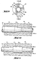
- radial incisions 46, 46a to 46n can now be made in the manner shown in FIG. 9 on the inner circumference of the passage opening 41, which cut through the fibers present there in the circumferential direction and divide them into individual fields which are not connected to one another.
- the inner circumference of the passage opening 41 can be used in selective areas or overall as a bearing recess 43, as can be seen in FIGS. 10 and 11, so that even smooth pipelines with an oversize pipe diameter can still be accommodated without problems and, in particular, discontinuities can be insulated without problems can.
- FIG. 10 shows an application in which a pipeline 42 is continued with a changed diameter by means of a conical transition piece 42a.
- the incisions 46, 46a... 46n running parallel to the pipe axis enable compression of the mineral fiber material on the inner circumference of the passage opening 41 to adapt to the increasing diameter of the pipe in the area of the transition piece 42a and the following larger pipe diameter.
- an insulating shell 40 is to be selected, the passage opening 41 of which has a diameter which at most corresponds to the smallest pipe diameter that occurs, so that it still encompasses the system and larger pipe diameters can be accommodated by appropriate compression.
- a pipe socket connection is used as a component 44a to be received in a line 44.
- this like the transition piece 42a, is easily accommodated by local compression of the insulating material on the inner circumference of the passage opening 41 and a recess 43 is thus formed.
- FIGS. 12 and 13 Another form of adaptation of a pipe insulation shell 50 according to the invention is illustrated in FIGS. 12 and 13.
- the pipe insulation shell 50 in turn has a continuous slot 57 and an opposite incision 57a to facilitate the opening movement.
- the incision 57a is used here as well as the slot 57 in the sense of an incision according to the invention, and moreover two further incisions 56 and 56a are made at an angle of 90 degrees to the slot 57 and the incision 57a, respectively.
- the insulating shell 50 in the manner shown in FIG.
- 13 is suitable for receiving a tube with a square cross-section as component 52, with each of the corners of the tube coming to rest on one of the incisions or slots 56, 56a, 57, 57a and the Flat sides of the component 52 between the corners correspondingly compressed the mineral fiber material between the incisions or slots 56, 56a, 57, 57a.
- the illustrated embodiment also facilitates the closing of the insulating shell 50 to close the slot 57 after the slipping on the square tube forming the component 52.
- a mineral fiber insulating shell 60 is intended to receive a component 62 which is not designed as a tube but as a bundle of two tubes.
- the mineral fiber shell 60 in turn has a slot 67 with an opposite incision 67a, but additionally, in the example case, incisions 66, 66a, 66b and 66c arranged perpendicular to this and tangential to the passage opening 61, as can be seen in detail in FIG. 14.
- the mineral fiber material between the incisions 66 and 66a on the one hand and 66b and 66c on the other hand is thereby radially compressible regardless of the surrounding material.
- the two tubes of the component 62 can be received in the manner shown in FIG. 15, a corresponding depression 63 being formed between the incisions 66, 66a and 66b and 66c by compression.
- a mineral fiber insulation shell 70 is provided, which in turn has a slot 77 and an incision 77a opposite it. Transversely to the plane of the slot 77, two incisions 76 and 76a are made in the manner according to the invention, which have a smaller mutual spacing than the diameter of the passage opening 71.
- a pipe 74 is to be received here in the passage opening 71 without deformation, on which a tubular heating element with a smaller diameter is attached as a component 72 to be additionally accommodated.
- the distance between the incisions 76 and 76a corresponds essentially to the diameter of the component 72 designed as a tubular heating element, so that it can enter between the incisions 76 and 76a and that there Can compress material to form a recess 73.
- FIGS. 18 to 20 illustrate a mineral fiber insulation body 80 which, in the example, is not slotted and only has an inner passage opening 81 which is closed on the circumference. While in the previously explained embodiments the formation of a depression 43, 53, 63 and 73 is always provided radially outward from the inner circumference of the passage opening of the respective insulating shell, the present embodiment according to FIGS. 18 to 20 illustrates the corresponding possibility of forming depressions 83 radially from the outside inwards in the outer circumferential surface of the insulating shell 80.
- incisions 86, 86a or 86b and 86c or 86d and 86e or 86f and 86g which are arranged in pairs, are provided, which are guided radially inward from the outer circumference of the insulating shell and in the example, are at an angular distance of 90 degrees.
- the material between the slots 86 as shown schematically in FIG. 19, can be compressed radially inward by suitable pressure tools 84 to form the depressions 83. Then, in the manner shown in FIG.
- the outer circumference of the mineral fiber insulating shell 80 can be surrounded with a tensioning jacket 85 and thus its diameter can be reduced, whereby under the pressure of the tensioning jacket 85 mineral fiber material is displaced from the web areas between the depressions 83 into the depressions 83 can. In this way, the mineral fiber insulating shell 80 can be reduced in its outer circumference, springing back when the tensioning shell 85 is removed and essentially the original circumference of the mineral fiber insulating shell 80 is restored.
- the mineral fiber insulation shell 80 By reducing the outside diameter of the mineral fiber insulation shell 80 by means of such a tension jacket. 85, for example, such an insulating shell press can be installed in installation bodies, such as fireplaces or the like, which are only accessible from the interior. For this purpose, the outer diameter is first reduced by means of the clamping jacket 85 and is thus carried out. insertion with little resistance, while the tensioning jacket 85 can then be opened or otherwise removed and the mineral fiber insulating shell 80 springs back accordingly.
- the mineral fiber insulation shell 80 also adapts to irregular internal contours of the receiving component, for which purpose the cuts 86 can also be used to improve the adaptability. Inwardly projecting projections or the like of the installation body, such as, for example, a pipeline or the like guided on the inner circumference, can also be received in a clean manner.
Landscapes
- Engineering & Computer Science (AREA)
- General Engineering & Computer Science (AREA)
- Mechanical Engineering (AREA)
- Thermal Insulation (AREA)
- Insulating Bodies (AREA)
Applications Claiming Priority (2)
| Application Number | Priority Date | Filing Date | Title |
|---|---|---|---|
| DE3235294 | 1982-09-23 | ||
| DE19823235294 DE3235294A1 (de) | 1982-09-23 | 1982-09-23 | Mineralfaserdaemmkoerper, insbesondere formteil, aus mit bindemittel gebundenen mineralfasern, sowie hiermit hergestelltes topffoermiges teil, verbundbauteil und hieraus hergestellte mineralfaserdaemmschale |
Publications (2)
| Publication Number | Publication Date |
|---|---|
| EP0104597A2 true EP0104597A2 (fr) | 1984-04-04 |
| EP0104597A3 EP0104597A3 (fr) | 1985-10-02 |
Family
ID=6173990
Family Applications (1)
| Application Number | Title | Priority Date | Filing Date |
|---|---|---|---|
| EP83109366A Withdrawn EP0104597A3 (fr) | 1982-09-23 | 1983-09-21 | Corps isolant, en particulier corps façonné, à base de fibres minérales et d'un liant et élément en forme de pot, matière composite et coquille isolante en dérivant |
Country Status (3)
| Country | Link |
|---|---|
| EP (1) | EP0104597A3 (fr) |
| AT (1) | AT384617B (fr) |
| DE (1) | DE3235294A1 (fr) |
Cited By (4)
| Publication number | Priority date | Publication date | Assignee | Title |
|---|---|---|---|---|
| FR2573005A1 (fr) * | 1984-11-12 | 1986-05-16 | Malvaux Sa | Procede de fabrication d'un panneau a plates-bandes |
| FR2627129A1 (fr) * | 1988-02-11 | 1989-08-18 | Allard Sarl | Procede d'assemblage de deux panneaux en carton ondule de meme epaisseur |
| WO2004078262A1 (fr) * | 2003-03-07 | 2004-09-16 | Dean Reeve | Dispositif de protection pour tete de distribution |
| WO2006123015A1 (fr) * | 2005-05-20 | 2006-11-23 | Paroc Oy Ab | Troncon de tuyau utilise a des fins d’isolation et son procede de fabrication |
Families Citing this family (2)
| Publication number | Priority date | Publication date | Assignee | Title |
|---|---|---|---|---|
| DE29622196U1 (de) | 1996-12-20 | 1997-02-20 | SAINT-GOBAIN ISOVER G+H AG, 67059 Ludwigshafen | Formteile aus Mineralwolle-Nadelfilz |
| DE19941746A1 (de) * | 1999-09-02 | 2001-03-08 | Porextherm Daemmstoffe Gmbh | Dämmformkörper und Verfahren zu dessen Herstellung |
Family Cites Families (9)
| Publication number | Priority date | Publication date | Assignee | Title |
|---|---|---|---|---|
| DE433121C (de) * | 1924-12-09 | 1926-08-20 | Mitteldeutsche Isolierwerk Ag | Isolierkappe fuer Rohrflansche |
| US3431335A (en) * | 1966-10-20 | 1969-03-04 | G S Staunton & Co Inc | Method and apparatus for making filters |
| DE2014555A1 (de) * | 1969-03-28 | 1970-11-12 | P,H, Thermal Products Ltd., Baildon, Yorkshire (Großbritannien) | Rohrisolierung |
| DE2223313C3 (de) * | 1972-05-12 | 1980-09-25 | Gernot 6331 Stockhausen Muellender | Isoliermantel aus halbstarrem, wärmedammendem Material, insbesondere halbstarrem Hartschaumstoff |
| DE2618813C3 (de) * | 1976-04-29 | 1978-11-16 | Heinz Christian 6360 Friedberg Krebs | Aufspritzbare, anorganische Fasern und Bindemittel enthaltende Masse für Schall-, Wärme- und Feuerschutzisolationen |
| IT1089605B (it) * | 1976-10-18 | 1985-06-18 | Italiana Petroli | Materiali e strutture per isolamenti termici ed acustici e procedimenti per la loro preparazione |
| DE2731729A1 (de) * | 1977-07-13 | 1979-02-01 | Gruenzweig Hartmann Glasfaser | Aus mineralfasern bestehende waermedaemmplatte |
| DE2848391A1 (de) * | 1978-11-08 | 1980-05-14 | Karl Klein Fa | Isolierrohr und verfahren zu seiner herstellung |
| DE2951660A1 (de) * | 1979-12-21 | 1981-07-02 | Dynamit Nobel Ag, 5210 Troisdorf | Isolierhuelle aus weichschaum und verfahren zu ihrer herstellung |
-
1982
- 1982-09-23 DE DE19823235294 patent/DE3235294A1/de active Granted
-
1983
- 1983-09-21 AT AT0991083A patent/AT384617B/de not_active IP Right Cessation
- 1983-09-21 EP EP83109366A patent/EP0104597A3/fr not_active Withdrawn
Cited By (4)
| Publication number | Priority date | Publication date | Assignee | Title |
|---|---|---|---|---|
| FR2573005A1 (fr) * | 1984-11-12 | 1986-05-16 | Malvaux Sa | Procede de fabrication d'un panneau a plates-bandes |
| FR2627129A1 (fr) * | 1988-02-11 | 1989-08-18 | Allard Sarl | Procede d'assemblage de deux panneaux en carton ondule de meme epaisseur |
| WO2004078262A1 (fr) * | 2003-03-07 | 2004-09-16 | Dean Reeve | Dispositif de protection pour tete de distribution |
| WO2006123015A1 (fr) * | 2005-05-20 | 2006-11-23 | Paroc Oy Ab | Troncon de tuyau utilise a des fins d’isolation et son procede de fabrication |
Also Published As
| Publication number | Publication date |
|---|---|
| DE3235294C2 (fr) | 1987-10-22 |
| AT384617B (de) | 1987-12-10 |
| ATA991083A (de) | 1987-05-15 |
| EP0104597A3 (fr) | 1985-10-02 |
| DE3235294A1 (de) | 1984-03-29 |
Similar Documents
| Publication | Publication Date | Title |
|---|---|---|
| DE69003324T2 (de) | Vorrichtung und Verfahren zum Ausstanzen einer Blechplatine. | |
| DE2429474A1 (de) | Filterpatrone und verfahren zu ihrer herstellung | |
| DE3232823C2 (fr) | ||
| EP1156897B1 (fr) | Coussinet lisse enroule | |
| DE69711696T2 (de) | Verfahren zum quereinpressen eines zylindrischen teils in ein rohrförmiges teil und entsprechende einheit aus zwei teilen | |
| DE2509107C2 (de) | Verfahren zum Herstellen eines Kommutators | |
| DE102019113211A1 (de) | Verfahren zur Herstellung eines Biegeteils | |
| EP0204890B1 (fr) | Procédé pour la fabrication d'éléments de construction | |
| DE3018985C2 (de) | Verfahren zum Verarbeiten von natürlich gewachsenen, sich konisch verjüngenden Baumstämmen | |
| DE1760440A1 (de) | Nadel fuer Verfilzungszwecke | |
| DE3235294C2 (fr) | ||
| DE3149541A1 (de) | Verfahren zum herstellen eines dichtelements | |
| EP0325690B1 (fr) | Procédé de fabrication d'une pièce en contre-plaqué avec placage en bois et l'outil de poinçonnage pour sa mise en oeuvre et produit ainsi obtenu | |
| DE20013640U1 (de) | Spülebecken | |
| DE19613180A1 (de) | Verfahren zum Fließpressen eines Formkörpers | |
| EP1116531B1 (fr) | Procédé de fabrication de tôles à bords biseautes | |
| DE3886954T2 (de) | Einrichtung zum Ineinandergreifen von Platten. | |
| DE2847023C2 (de) | Spiegelpreßschweißvorrichtung zum Verbinden von Kunststoffprofilen | |
| DE3447239A1 (de) | Kunststoff-kammerprofil mit eingebauter metallschiene und vorrichtung zur herstellung derartiger kammerprofile | |
| DE69501747T2 (de) | Fertigungsteil für eine Rahmenstruktur, daraus bestehende Rahmenstruktur und Verfahren zur Herstellung derselben | |
| DE20121504U1 (de) | Dichtring | |
| WO2001086091A1 (fr) | Dispositif d'isolation, procede pour remplir des moulures de toles profilees avec un garnissage, dispositif pour mettre en oeuvre ledit procede et procede de production d'un dispositif d'isolation | |
| DE19515791A1 (de) | Vorrichtung zur Herstellung von Glasfaser-Vorformlingen aus Glasfasermatten | |
| DE2354246C2 (de) | Bauelement | |
| DE1528296C (de) | Abwicklungsform zur Herstellung emes kastenförmigen Formkorpers aus einem vorge preßten Faservlies |
Legal Events
| Date | Code | Title | Description |
|---|---|---|---|
| PUAI | Public reference made under article 153(3) epc to a published international application that has entered the european phase |
Free format text: ORIGINAL CODE: 0009012 |
|
| AK | Designated contracting states |
Designated state(s): AT BE CH DE FR IT LI NL |
|
| PUAL | Search report despatched |
Free format text: ORIGINAL CODE: 0009013 |
|
| AK | Designated contracting states |
Designated state(s): AT BE CH DE FR IT LI NL |
|
| STAA | Information on the status of an ep patent application or granted ep patent |
Free format text: STATUS: THE APPLICATION HAS BEEN WITHDRAWN |
|
| 18W | Application withdrawn |
Withdrawal date: 19851115 |
|
| RIN1 | Information on inventor provided before grant (corrected) |
Inventor name: SOMMER, ROLF |