EP0104629A1 - Panneau de construction combiné - Google Patents
Panneau de construction combiné Download PDFInfo
- Publication number
- EP0104629A1 EP0104629A1 EP83109505A EP83109505A EP0104629A1 EP 0104629 A1 EP0104629 A1 EP 0104629A1 EP 83109505 A EP83109505 A EP 83109505A EP 83109505 A EP83109505 A EP 83109505A EP 0104629 A1 EP0104629 A1 EP 0104629A1
- Authority
- EP
- European Patent Office
- Prior art keywords
- plate
- sheet metal
- concrete
- construction
- bottom construction
- Prior art date
- Legal status (The legal status is an assumption and is not a legal conclusion. Google has not performed a legal analysis and makes no representation as to the accuracy of the status listed.)
- Granted
Links
- 238000010276 construction Methods 0.000 title claims abstract description 65
- 239000002184 metal Substances 0.000 claims abstract description 79
- 229910052751 metal Inorganic materials 0.000 claims abstract description 79
- 239000004567 concrete Substances 0.000 claims abstract description 43
- 229910000831 Steel Inorganic materials 0.000 claims abstract description 16
- 239000010959 steel Substances 0.000 claims abstract description 16
- 238000005266 casting Methods 0.000 claims abstract description 12
- 239000002023 wood Substances 0.000 claims description 9
- 239000000463 material Substances 0.000 claims description 4
- 238000010008 shearing Methods 0.000 claims description 4
- 239000010426 asphalt Substances 0.000 claims description 2
- 239000010440 gypsum Substances 0.000 claims description 2
- 229910052602 gypsum Inorganic materials 0.000 claims description 2
- 230000002787 reinforcement Effects 0.000 abstract description 4
- 238000000034 method Methods 0.000 description 4
- 239000007787 solid Substances 0.000 description 3
- 238000004078 waterproofing Methods 0.000 description 3
- 239000004035 construction material Substances 0.000 description 2
- 230000000694 effects Effects 0.000 description 2
- 239000002390 adhesive tape Substances 0.000 description 1
- 238000005452 bending Methods 0.000 description 1
- 239000004568 cement Substances 0.000 description 1
- 230000003467 diminishing effect Effects 0.000 description 1
- 238000010030 laminating Methods 0.000 description 1
- 150000002739 metals Chemical class 0.000 description 1
- 239000003973 paint Substances 0.000 description 1
- 230000035515 penetration Effects 0.000 description 1
- 238000004904 shortening Methods 0.000 description 1
- 239000007921 spray Substances 0.000 description 1
- 239000002351 wastewater Substances 0.000 description 1
- XLYOFNOQVPJJNP-UHFFFAOYSA-N water Substances O XLYOFNOQVPJJNP-UHFFFAOYSA-N 0.000 description 1
Images
Classifications
-
- E—FIXED CONSTRUCTIONS
- E04—BUILDING
- E04B—GENERAL BUILDING CONSTRUCTIONS; WALLS, e.g. PARTITIONS; ROOFS; FLOORS; CEILINGS; INSULATION OR OTHER PROTECTION OF BUILDINGS
- E04B5/00—Floors; Floor construction with regard to insulation; Connections specially adapted therefor
- E04B5/02—Load-carrying floor structures formed substantially of prefabricated units
- E04B5/10—Load-carrying floor structures formed substantially of prefabricated units with metal beams or girders, e.g. with steel lattice girders
-
- E—FIXED CONSTRUCTIONS
- E04—BUILDING
- E04C—STRUCTURAL ELEMENTS; BUILDING MATERIALS
- E04C2/00—Building elements of relatively thin form for the construction of parts of buildings, e.g. sheet materials, slabs, or panels
- E04C2/02—Building elements of relatively thin form for the construction of parts of buildings, e.g. sheet materials, slabs, or panels characterised by specified materials
- E04C2/26—Building elements of relatively thin form for the construction of parts of buildings, e.g. sheet materials, slabs, or panels characterised by specified materials composed of materials covered by two or more of groups E04C2/04, E04C2/08, E04C2/10 or of materials covered by one of these groups with a material not specified in one of the groups
- E04C2/28—Building elements of relatively thin form for the construction of parts of buildings, e.g. sheet materials, slabs, or panels characterised by specified materials composed of materials covered by two or more of groups E04C2/04, E04C2/08, E04C2/10 or of materials covered by one of these groups with a material not specified in one of the groups combinations of materials fully covered by groups E04C2/04 and E04C2/08
-
- E—FIXED CONSTRUCTIONS
- E04—BUILDING
- E04B—GENERAL BUILDING CONSTRUCTIONS; WALLS, e.g. PARTITIONS; ROOFS; FLOORS; CEILINGS; INSULATION OR OTHER PROTECTION OF BUILDINGS
- E04B5/00—Floors; Floor construction with regard to insulation; Connections specially adapted therefor
- E04B5/16—Load-carrying floor structures wholly or partly cast or similarly formed in situ
- E04B5/17—Floor structures partly formed in situ
- E04B5/23—Floor structures partly formed in situ with stiffening ribs or other beam-like formations wholly or partly prefabricated
- E04B2005/232—Floor structures partly formed in situ with stiffening ribs or other beam-like formations wholly or partly prefabricated with special provisions for connecting wooden stiffening ribs or other wooden beam-like formations to the concrete slab
- E04B2005/237—Separate connecting elements
Definitions
- the present invention relates to a combined construction plate, which is combined of a castable or cementable or other such element, made for example of concrete bitumen or gypsum and of thin plate such as steel sheet, or canvas or other such bottom construction, which construction can have the form of a beam, a framework or a plate, or a combination thereof.
- Combined construction plates are mainly used as horizontal plates in buildings.
- the sheet metal and the concrete function together, so that the sheet metal serves both as the reinforcement and as the casting mould of the plate.
- profiled sheet metal has been used in such plates, and the following drawbacks can be enlisted:
- the present invention is based on the observation that below the said combined construction plates there is practically always attached some kind of suspended ceiling and/or beamwork supporting the plate.
- This ceiling and/or beamwork is hereinafter called the bottom construction.
- the ceiling may be necessary for esthetic or acoustic reasons, or because of fire safety or the necessity to cover pipeworks.
- the beamwork supporting the plate is generally always necessary with large spans, because the combined plate of sheet metal and concrete stretches out to relatively short spans (roughly 4-6 m) only.
- the beamwork can be an ordinary beam, but it can also be a framework or a plate, and it can be made of steel, concrete, wood or other suitable material.
- the purpose of the present invention is to eliminate the aforementioned drawbacks and to realize a.combined construction plate where the bottom construction, the sheet metal and the concrete form a construction which is at least partially co-functioning. This is achieved by means of the characteristic features of the invention, which are enlisted in the Patent Claim 1.
- the upper part of the bottom construction is provided with spikes or for example serrated, and the sheet metal is hammered or pressed against the said spikes.
- the spikes attach the bottom construction to the sheet metal and to the concrete, and the sheet metal at least partially to the concrete, as well as the sheets of metal to each other.
- the spikes can be attached to the bottom construction also by hammering them through the sheet metal. This kind of procedure is particularly suitable if the bottom construction is made of wood.
- the sheet metal is unprofiled and the beam-like members of the bottom construction, as well as the spikes thereof, are located relatively near to each other.
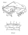
- the bottom construction of the combined construction plate is a steel beamwork 4, where the beam itself is made of Z-profile by splitting it so that spikes 3 are formed in the beam. It is normally advisable to carry out the splitting so that the plate will be provided with gaps 5. Thus it is possible to save material, and piping adjustments can be made inside the plate in the transversal direction of the beams 4.
- the sheet metal 2 is laminated at the beam 4 and folded at the edge to form the casting mould 6. It is generally advisable to cut teeth in the spikes 3 of the beam 4 in order to improve the concrete grip.
- the row of spikes should also be designed so that it has a wave-like form, in order to avoid a weak, straight line in the sheet metal.
- the row of spikes should be designed so that it has a groove-shaped cross-section in order to make the spikes penetrate the sheet metal and prevent them from bending aside.
- the concrete 1 is cast on top of the sheet metal. If the spikes belong to the bottom construction, the sheet metal can be attached thereto for example by mounting it on top of the bottom construction.
- the sheet metal is hammered for example with a rubber-headed or a wooden hammer, so that the spikes penetrate the sheet.
- the beam 4a At the end of the plate, there can be arranged in transversal direction the beam 4a, which is particularly useful if the sheet metal is unprofiled:
- the sheet metal can naturally be adjusted on top of the beams 4 in transversal direction, too, but generally it is not recommendable from the point of view of Constructional reasons and working techniques.
- the sheet metal can also be profiled, in which case. the interval between the beams 4 can be long.
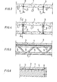
- Figure 4 shows a cross-section view of such a combined plate where the bottom construction is a concrete slab with a steel grate attached thereto.
- the spikes 3 are cut in the pair of bars functioning as the upper beam of the steel grate.
- This is profitable because now there will be only a small amount of sheet metal penetrations in a same straight line, but the junction between the sheet metal and the concrete becomes firm - for example it endures transversal traction, which is important if the plate should function constructionally in two directions.
- the construction of Figures 4 and 5 can also be used without the concrete slab which is located underneath.
- Figure 6 shows a lengthwise cross-section view of such a plate where the bottom construction is formed of wooden beams.
- Such a construction is particularly advantageous in small houses, specially in floors, ceilings and all kinds of thermally insulated structures, among others as outer walls of light industrial halls.
- the bottom construction is made of wood, it is possible to attach the sheet metal-concrete plate to the bottom construction by means of a truss plate with dented edges.
- Sheet metal and concrete can be attached to the bottom construction also by nailing the sheet metal to the wood so that the head of the nail is left slightly apart from the sheet metal.
- the so-called two-headed nail is particularly suitable for this purpose.
- a truss plate is employed in fixing the plate, it is possible to leave a gap between the sheet metal and the wood.
- a transversal board or equivalent can then be placed at the gap to support the metal sheet, in which case the intervals between the wooden beams can be comparatively long.
- the bottom construction can also be of some other type; it can be for example an element of profiled sheet metal as in the Finnish Publication Print 51628 or a wooden framework as in the Finnish Publication Print 60752.
- One advantageous and important embodiment of the invention relates to the ceiling of a building with a low- pitched roof.
- the concrete can be made so that it is resistant to weather; a separate water proofing is generally unnecessary, or the water proofing can be simpler than normally - for example an insulating layer of paint or spray - because sheet metal is a compact construction material. This leads to remarkable savings in building costs, because in conventional building it has been necessary to provide the construction with separate water proofing.
- the bottom construction material is wood and the spikes are nails, it is profitable to carry out the nailing so that the shift, which is the outcome of the shearing strain in the juncture, tightens the sheet metal against the wood.
- Such an effect is achieved by hitting the nails in a slanted position in the direction of the diminishing shearing force of the wood, i.e. so that the head of the nail points to the middle of the span.
- the sheet metal used in the plate of the invention is normally smooth, but when long mutual intervals are used in the bottom construction, it is necessary to stiffen the sheet metal for example by profiling. A particularly good result is achieved if the sheet metal is trans- vbrsally profiled only in the middle part. Alternatively it.is possible to use the transversal supports which are employed during the casting or which remain as parts of the bottom construction; a plurality of wide-spaced boards placed under the sheet metal is economical in several different applications. If the bottom construction has long intervals, it is easy to corrugate the sheet metal by providing the top surface of the bottom construction with a wave-like shape.
- One remarkable embodiment of the invention is a plate with self-levelling cast.
- the volume price of such a cast is from 2 to 20 times higher than that of an ordinary cast. Therefore it is important that the layer of concrete is as thin as possible.
- the thickness of the layer of concrete can be reduced to one fourth of the cast thickness of an ordinary construction plate.
Landscapes
- Architecture (AREA)
- Engineering & Computer Science (AREA)
- Civil Engineering (AREA)
- Structural Engineering (AREA)
- Physics & Mathematics (AREA)
- Electromagnetism (AREA)
- Forms Removed On Construction Sites Or Auxiliary Members Thereof (AREA)
- Solid-Sorbent Or Filter-Aiding Compositions (AREA)
- Catching Or Destruction (AREA)
- Road Paving Structures (AREA)
- Chemical And Physical Treatments For Wood And The Like (AREA)
- Buildings Adapted To Withstand Abnormal External Influences (AREA)
- Agricultural Chemicals And Associated Chemicals (AREA)
- Joining Of Building Structures In Genera (AREA)
Priority Applications (1)
| Application Number | Priority Date | Filing Date | Title |
|---|---|---|---|
| AT83109505T ATE20109T1 (de) | 1982-09-23 | 1983-09-23 | Zusammengesetzte bauplatte. |
Applications Claiming Priority (2)
| Application Number | Priority Date | Filing Date | Title |
|---|---|---|---|
| FI823268 | 1982-09-23 | ||
| FI823268A FI66229C (fi) | 1982-09-23 | 1982-09-23 | Sammasatt platta |
Publications (2)
| Publication Number | Publication Date |
|---|---|
| EP0104629A1 true EP0104629A1 (fr) | 1984-04-04 |
| EP0104629B1 EP0104629B1 (fr) | 1986-05-28 |
Family
ID=8516069
Family Applications (1)
| Application Number | Title | Priority Date | Filing Date |
|---|---|---|---|
| EP83109505A Expired EP0104629B1 (fr) | 1982-09-23 | 1983-09-23 | Panneau de construction combiné |
Country Status (4)
| Country | Link |
|---|---|
| EP (1) | EP0104629B1 (fr) |
| AT (1) | ATE20109T1 (fr) |
| DE (1) | DE3363783D1 (fr) |
| FI (1) | FI66229C (fr) |
Cited By (4)
| Publication number | Priority date | Publication date | Assignee | Title |
|---|---|---|---|---|
| FR2733263A1 (fr) * | 1995-04-24 | 1996-10-25 | Termes Chantal Sylvie | Panneau composite, assemblage de panneaux et batiment de type prefabrique construit a l'aide de tels panneaux |
| EP0828033A3 (fr) * | 1996-09-04 | 1999-01-13 | Peter Dr.-Ing. Maack | Dalles pour planchers de bâtiments |
| AT1676U3 (de) * | 1997-06-17 | 1999-01-25 | Goedl Albin | Blech, fertigbauteil aus blech und verfahren zu dessen herstellung |
| AT409512B (de) * | 1997-06-17 | 2002-09-25 | Goedl Albin | Blech, fertigbauteil aus blech und verfahren zu dessen herstellung |
Citations (8)
| Publication number | Priority date | Publication date | Assignee | Title |
|---|---|---|---|---|
| BE567883A (fr) * | ||||
| CH19273A (de) * | 1899-04-27 | 1900-06-15 | A Dr Katz | Kunststein mit Holzbekleidung |
| DE843152C (de) * | 1948-08-20 | 1952-07-07 | Norbert Dipl-Archi Schlesinger | Auf Biegung beanspruchter Bauteil, insbesondere Bauplatte |
| DE2413645A1 (de) * | 1974-03-21 | 1975-09-25 | Bernhard Dr Ing Unger | Verbundplatte aus beton und profilblechelementen |
| DE2600662A1 (de) * | 1976-01-09 | 1977-07-21 | Westeel Rosco Ltd | Zusammengesetzte baueinheit |
| DE2700588A1 (de) * | 1977-01-07 | 1978-07-20 | Jungbluth Otto Prof Dr Ing | Stahlprofilblech/betonverbundplatte |
| DE2700416B2 (de) * | 1977-01-07 | 1979-11-22 | Otto Prof. Dr.-Ing. 6100 Darmstadt Jungbluth | Mehrschichtiges Verbundtragwerk |
| DE2924960A1 (de) * | 1979-06-21 | 1981-01-22 | Gholam Resa Prof Dr Ing Kuros | Verbund-bauelement |
-
1982
- 1982-09-23 FI FI823268A patent/FI66229C/fi not_active IP Right Cessation
-
1983
- 1983-09-23 EP EP83109505A patent/EP0104629B1/fr not_active Expired
- 1983-09-23 DE DE8383109505T patent/DE3363783D1/de not_active Expired
- 1983-09-23 AT AT83109505T patent/ATE20109T1/de not_active IP Right Cessation
Patent Citations (8)
| Publication number | Priority date | Publication date | Assignee | Title |
|---|---|---|---|---|
| BE567883A (fr) * | ||||
| CH19273A (de) * | 1899-04-27 | 1900-06-15 | A Dr Katz | Kunststein mit Holzbekleidung |
| DE843152C (de) * | 1948-08-20 | 1952-07-07 | Norbert Dipl-Archi Schlesinger | Auf Biegung beanspruchter Bauteil, insbesondere Bauplatte |
| DE2413645A1 (de) * | 1974-03-21 | 1975-09-25 | Bernhard Dr Ing Unger | Verbundplatte aus beton und profilblechelementen |
| DE2600662A1 (de) * | 1976-01-09 | 1977-07-21 | Westeel Rosco Ltd | Zusammengesetzte baueinheit |
| DE2700588A1 (de) * | 1977-01-07 | 1978-07-20 | Jungbluth Otto Prof Dr Ing | Stahlprofilblech/betonverbundplatte |
| DE2700416B2 (de) * | 1977-01-07 | 1979-11-22 | Otto Prof. Dr.-Ing. 6100 Darmstadt Jungbluth | Mehrschichtiges Verbundtragwerk |
| DE2924960A1 (de) * | 1979-06-21 | 1981-01-22 | Gholam Resa Prof Dr Ing Kuros | Verbund-bauelement |
Cited By (5)
| Publication number | Priority date | Publication date | Assignee | Title |
|---|---|---|---|---|
| FR2733263A1 (fr) * | 1995-04-24 | 1996-10-25 | Termes Chantal Sylvie | Panneau composite, assemblage de panneaux et batiment de type prefabrique construit a l'aide de tels panneaux |
| WO1996034158A1 (fr) * | 1995-04-24 | 1996-10-31 | Chantal Termes | Panneau composite, assemblage de panneaux et batiment de type prefabrique construit a l'aide de tels panneaux |
| EP0828033A3 (fr) * | 1996-09-04 | 1999-01-13 | Peter Dr.-Ing. Maack | Dalles pour planchers de bâtiments |
| AT1676U3 (de) * | 1997-06-17 | 1999-01-25 | Goedl Albin | Blech, fertigbauteil aus blech und verfahren zu dessen herstellung |
| AT409512B (de) * | 1997-06-17 | 2002-09-25 | Goedl Albin | Blech, fertigbauteil aus blech und verfahren zu dessen herstellung |
Also Published As
| Publication number | Publication date |
|---|---|
| FI66229B (fi) | 1984-05-31 |
| FI66229C (fi) | 1984-09-10 |
| ATE20109T1 (de) | 1986-06-15 |
| EP0104629B1 (fr) | 1986-05-28 |
| DE3363783D1 (en) | 1986-07-03 |
| FI823268A0 (fi) | 1982-09-23 |
Similar Documents
| Publication | Publication Date | Title |
|---|---|---|
| US6691482B1 (en) | Decking | |
| JP3692038B2 (ja) | 建築方法とそれによる構造物 | |
| CA2116620A1 (fr) | Element de construction composite bois-beton | |
| US20070283643A1 (en) | Preformed wall panel | |
| US5647186A (en) | Steel framing system for walls | |
| US5581969A (en) | Prefabricated building element | |
| US20070000197A1 (en) | Structural decking system | |
| US5341611A (en) | Structural framing system for buildings | |
| EP0104629B1 (fr) | Panneau de construction combiné | |
| EP0110849B1 (fr) | Panneau formant une surface | |
| US8539730B2 (en) | Building system | |
| EP0815330B1 (fr) | Element en plaque composite | |
| JP7744545B1 (ja) | デッキプレートと天井仕上げ木質板とを梁に設置する方法 | |
| JPS60215957A (ja) | プレハブ構造用壁板及び該壁板を含むプレハブ構造 | |
| EP0015973A1 (fr) | Toit | |
| JP2980199B2 (ja) | 建築物構造 | |
| WO1994000652A1 (fr) | Element prefabrique de construction | |
| AU2004206038B2 (en) | Structural decking system | |
| AU2009101215B4 (en) | Strutting Beam for use in Roofing Structure | |
| JPH1030302A (ja) | 壁用骨組み用部材、該部材を用いた壁用骨組みシステム、及び該システムを組み立てる方法 | |
| JPH06257213A (ja) | 屋根パネルと壁パネルとの接合構造 | |
| JP2000136593A (ja) | 床用構造体 | |
| AU761616B2 (en) | Construction technique and structure resulting therefrom | |
| EP0161254A1 (fr) | Element de surface prefabrique de type composite | |
| JP2002285660A (ja) | 枠組壁工法による建築物 |
Legal Events
| Date | Code | Title | Description |
|---|---|---|---|
| PUAI | Public reference made under article 153(3) epc to a published international application that has entered the european phase |
Free format text: ORIGINAL CODE: 0009012 |
|
| AK | Designated contracting states |
Designated state(s): AT BE DE FR GB NL SE |
|
| 17P | Request for examination filed |
Effective date: 19840927 |
|
| GRAA | (expected) grant |
Free format text: ORIGINAL CODE: 0009210 |
|
| AK | Designated contracting states |
Kind code of ref document: B1 Designated state(s): AT BE DE FR GB NL SE |
|
| PG25 | Lapsed in a contracting state [announced via postgrant information from national office to epo] |
Ref country code: NL Effective date: 19860528 |
|
| RAP1 | Party data changed (applicant data changed or rights of an application transferred) |
Owner name: POUTANEN, TUOMO TAPANI |
|
| REF | Corresponds to: |
Ref document number: 20109 Country of ref document: AT Date of ref document: 19860615 Kind code of ref document: T |
|
| REF | Corresponds to: |
Ref document number: 3363783 Country of ref document: DE Date of ref document: 19860703 |
|
| ET | Fr: translation filed | ||
| PGFP | Annual fee paid to national office [announced via postgrant information from national office to epo] |
Ref country code: AT Payment date: 19860909 Year of fee payment: 4 |
|
| NLV1 | Nl: lapsed or annulled due to failure to fulfill the requirements of art. 29p and 29m of the patents act | ||
| PLBE | No opposition filed within time limit |
Free format text: ORIGINAL CODE: 0009261 |
|
| STAA | Information on the status of an ep patent application or granted ep patent |
Free format text: STATUS: NO OPPOSITION FILED WITHIN TIME LIMIT |
|
| 26N | No opposition filed | ||
| PG25 | Lapsed in a contracting state [announced via postgrant information from national office to epo] |
Ref country code: AT Effective date: 19890923 |
|
| PG25 | Lapsed in a contracting state [announced via postgrant information from national office to epo] |
Ref country code: BE Effective date: 19890930 |
|
| BERE | Be: lapsed |
Owner name: POUTANEN TUOMO TAPANI Effective date: 19890930 |
|
| PGFP | Annual fee paid to national office [announced via postgrant information from national office to epo] |
Ref country code: FR Payment date: 19940909 Year of fee payment: 12 |
|
| PGFP | Annual fee paid to national office [announced via postgrant information from national office to epo] |
Ref country code: GB Payment date: 19940913 Year of fee payment: 12 |
|
| PGFP | Annual fee paid to national office [announced via postgrant information from national office to epo] |
Ref country code: DE Payment date: 19940921 Year of fee payment: 12 |
|
| EAL | Se: european patent in force in sweden |
Ref document number: 83109505.4 |
|
| PGFP | Annual fee paid to national office [announced via postgrant information from national office to epo] |
Ref country code: SE Payment date: 19950822 Year of fee payment: 13 |
|
| PG25 | Lapsed in a contracting state [announced via postgrant information from national office to epo] |
Ref country code: GB Effective date: 19950923 |
|
| GBPC | Gb: european patent ceased through non-payment of renewal fee |
Effective date: 19950923 |
|
| PG25 | Lapsed in a contracting state [announced via postgrant information from national office to epo] |
Ref country code: FR Effective date: 19960531 |
|
| PG25 | Lapsed in a contracting state [announced via postgrant information from national office to epo] |
Ref country code: DE Effective date: 19960601 |
|
| REG | Reference to a national code |
Ref country code: FR Ref legal event code: ST |
|
| PG25 | Lapsed in a contracting state [announced via postgrant information from national office to epo] |
Ref country code: SE Effective date: 19960924 |
|
| EUG | Se: european patent has lapsed |
Ref document number: 83109505.4 |