EP0104713B1 - Réfrigérateur magnétique - Google Patents
Réfrigérateur magnétique Download PDFInfo
- Publication number
- EP0104713B1 EP0104713B1 EP83303090A EP83303090A EP0104713B1 EP 0104713 B1 EP0104713 B1 EP 0104713B1 EP 83303090 A EP83303090 A EP 83303090A EP 83303090 A EP83303090 A EP 83303090A EP 0104713 B1 EP0104713 B1 EP 0104713B1
- Authority
- EP
- European Patent Office
- Prior art keywords
- working material
- heat
- cooling
- heat pipe
- space
- Prior art date
- Legal status (The legal status is an assumption and is not a legal conclusion. Google has not performed a legal analysis and makes no representation as to the accuracy of the status listed.)
- Expired
Links
- 239000008207 working material Substances 0.000 claims description 112
- 238000001816 cooling Methods 0.000 claims description 26
- 230000002093 peripheral effect Effects 0.000 claims description 19
- 239000007787 solid Substances 0.000 claims description 3
- 239000002826 coolant Substances 0.000 claims 4
- 239000001307 helium Substances 0.000 description 35
- 229910052734 helium Inorganic materials 0.000 description 35
- SWQJXJOGLNCZEY-UHFFFAOYSA-N helium atom Chemical compound [He] SWQJXJOGLNCZEY-UHFFFAOYSA-N 0.000 description 35
- 239000007789 gas Substances 0.000 description 22
- 238000000034 method Methods 0.000 description 10
- 239000007788 liquid Substances 0.000 description 8
- 230000008569 process Effects 0.000 description 8
- ZPDRQAVGXHVGTB-UHFFFAOYSA-N gallium;gadolinium(3+);oxygen(2-) Chemical compound [O-2].[O-2].[O-2].[Ga+3].[Gd+3] ZPDRQAVGXHVGTB-UHFFFAOYSA-N 0.000 description 6
- 239000000696 magnetic material Substances 0.000 description 5
- 239000000463 material Substances 0.000 description 5
- PXHVJJICTQNCMI-UHFFFAOYSA-N Nickel Chemical compound [Ni] PXHVJJICTQNCMI-UHFFFAOYSA-N 0.000 description 4
- NBIIXXVUZAFLBC-UHFFFAOYSA-N Phosphoric acid Chemical compound OP(O)(O)=O NBIIXXVUZAFLBC-UHFFFAOYSA-N 0.000 description 4
- 238000007599 discharging Methods 0.000 description 4
- UFHFLCQGNIYNRP-UHFFFAOYSA-N Hydrogen Chemical compound [H][H] UFHFLCQGNIYNRP-UHFFFAOYSA-N 0.000 description 3
- 238000010521 absorption reaction Methods 0.000 description 3
- 238000005520 cutting process Methods 0.000 description 3
- 230000005347 demagnetization Effects 0.000 description 3
- 239000001257 hydrogen Substances 0.000 description 3
- 229910052739 hydrogen Inorganic materials 0.000 description 3
- 230000005415 magnetization Effects 0.000 description 3
- 238000005057 refrigeration Methods 0.000 description 3
- 238000007789 sealing Methods 0.000 description 3
- 229910001371 Er alloy Inorganic materials 0.000 description 2
- 229910000990 Ni alloy Inorganic materials 0.000 description 2
- 229910000147 aluminium phosphate Inorganic materials 0.000 description 2
- 239000007864 aqueous solution Substances 0.000 description 2
- 238000010276 construction Methods 0.000 description 2
- 238000005530 etching Methods 0.000 description 2
- 238000004519 manufacturing process Methods 0.000 description 2
- 239000003507 refrigerant Substances 0.000 description 2
- 229910045601 alloy Inorganic materials 0.000 description 1
- 239000000956 alloy Substances 0.000 description 1
- 230000008901 benefit Effects 0.000 description 1
- 230000005540 biological transmission Effects 0.000 description 1
- 238000001704 evaporation Methods 0.000 description 1
- 239000000284 extract Substances 0.000 description 1
- ZZUFCTLCJUWOSV-UHFFFAOYSA-N furosemide Chemical compound C1=C(Cl)C(S(=O)(=O)N)=CC(C(O)=O)=C1NCC1=CC=CO1 ZZUFCTLCJUWOSV-UHFFFAOYSA-N 0.000 description 1
- 238000005304 joining Methods 0.000 description 1
- 230000007246 mechanism Effects 0.000 description 1
- 238000012986 modification Methods 0.000 description 1
- 230000004048 modification Effects 0.000 description 1
- 230000000149 penetrating effect Effects 0.000 description 1
- 150000002909 rare earth metal compounds Chemical class 0.000 description 1
- 230000000630 rising effect Effects 0.000 description 1
- 238000007493 shaping process Methods 0.000 description 1
Images
Classifications
-
- C—CHEMISTRY; METALLURGY
- C04—CEMENTS; CONCRETE; ARTIFICIAL STONE; CERAMICS; REFRACTORIES
- C04B—LIME, MAGNESIA; SLAG; CEMENTS; COMPOSITIONS THEREOF, e.g. MORTARS, CONCRETE OR LIKE BUILDING MATERIALS; ARTIFICIAL STONE; CERAMICS; REFRACTORIES; TREATMENT OF NATURAL STONE
- C04B41/00—After-treatment of mortars, concrete, artificial stone or ceramics; Treatment of natural stone
- C04B41/53—After-treatment of mortars, concrete, artificial stone or ceramics; Treatment of natural stone involving the removal of at least part of the materials of the treated article, e.g. etching, drying of hardened concrete
- C04B41/5338—Etching
- C04B41/5353—Wet etching, e.g. with etchants dissolved in organic solvents
-
- C—CHEMISTRY; METALLURGY
- C09—DYES; PAINTS; POLISHES; NATURAL RESINS; ADHESIVES; COMPOSITIONS NOT OTHERWISE PROVIDED FOR; APPLICATIONS OF MATERIALS NOT OTHERWISE PROVIDED FOR
- C09K—MATERIALS FOR MISCELLANEOUS APPLICATIONS, NOT PROVIDED FOR ELSEWHERE
- C09K13/00—Etching, surface-brightening or pickling compositions
- C09K13/04—Etching, surface-brightening or pickling compositions containing an inorganic acid
-
- F—MECHANICAL ENGINEERING; LIGHTING; HEATING; WEAPONS; BLASTING
- F25—REFRIGERATION OR COOLING; COMBINED HEATING AND REFRIGERATION SYSTEMS; HEAT PUMP SYSTEMS; MANUFACTURE OR STORAGE OF ICE; LIQUEFACTION SOLIDIFICATION OF GASES
- F25B—REFRIGERATION MACHINES, PLANTS OR SYSTEMS; COMBINED HEATING AND REFRIGERATION SYSTEMS; HEAT PUMP SYSTEMS
- F25B21/00—Machines, plants or systems, using electric or magnetic effects
-
- H—ELECTRICITY
- H01—ELECTRIC ELEMENTS
- H01F—MAGNETS; INDUCTANCES; TRANSFORMERS; SELECTION OF MATERIALS FOR THEIR MAGNETIC PROPERTIES
- H01F1/00—Magnets or magnetic bodies characterised by the magnetic materials therefor; Selection of materials for their magnetic properties
- H01F1/01—Magnets or magnetic bodies characterised by the magnetic materials therefor; Selection of materials for their magnetic properties of inorganic materials
- H01F1/012—Magnets or magnetic bodies characterised by the magnetic materials therefor; Selection of materials for their magnetic properties of inorganic materials adapted for magnetic entropy change by magnetocaloric effect, e.g. used as magnetic refrigerating material
- H01F1/017—Compounds
-
- F—MECHANICAL ENGINEERING; LIGHTING; HEATING; WEAPONS; BLASTING
- F25—REFRIGERATION OR COOLING; COMBINED HEATING AND REFRIGERATION SYSTEMS; HEAT PUMP SYSTEMS; MANUFACTURE OR STORAGE OF ICE; LIQUEFACTION SOLIDIFICATION OF GASES
- F25B—REFRIGERATION MACHINES, PLANTS OR SYSTEMS; COMBINED HEATING AND REFRIGERATION SYSTEMS; HEAT PUMP SYSTEMS
- F25B2321/00—Details of machines, plants or systems, using electric or magnetic effects
- F25B2321/002—Details of machines, plants or systems, using electric or magnetic effects by using magneto-caloric effects
- F25B2321/0021—Details of machines, plants or systems, using electric or magnetic effects by using magneto-caloric effects with a static fixed magnet
-
- Y—GENERAL TAGGING OF NEW TECHNOLOGICAL DEVELOPMENTS; GENERAL TAGGING OF CROSS-SECTIONAL TECHNOLOGIES SPANNING OVER SEVERAL SECTIONS OF THE IPC; TECHNICAL SUBJECTS COVERED BY FORMER USPC CROSS-REFERENCE ART COLLECTIONS [XRACs] AND DIGESTS
- Y02—TECHNOLOGIES OR APPLICATIONS FOR MITIGATION OR ADAPTATION AGAINST CLIMATE CHANGE
- Y02B—CLIMATE CHANGE MITIGATION TECHNOLOGIES RELATED TO BUILDINGS, e.g. HOUSING, HOUSE APPLIANCES OR RELATED END-USER APPLICATIONS
- Y02B30/00—Energy efficient heating, ventilation or air conditioning [HVAC]
-
- Y—GENERAL TAGGING OF NEW TECHNOLOGICAL DEVELOPMENTS; GENERAL TAGGING OF CROSS-SECTIONAL TECHNOLOGIES SPANNING OVER SEVERAL SECTIONS OF THE IPC; TECHNICAL SUBJECTS COVERED BY FORMER USPC CROSS-REFERENCE ART COLLECTIONS [XRACs] AND DIGESTS
- Y02—TECHNOLOGIES OR APPLICATIONS FOR MITIGATION OR ADAPTATION AGAINST CLIMATE CHANGE
- Y02P—CLIMATE CHANGE MITIGATION TECHNOLOGIES IN THE PRODUCTION OR PROCESSING OF GOODS
- Y02P20/00—Technologies relating to chemical industry
- Y02P20/10—Process efficiency
Definitions
- This invention relates to a magnetic refrigerator using a working material which radiates heat when it is magnetized and absorbs heat when it is demagnetized.
- Magnetic refrigerators are based on the well-known phenomenon that working materials consisting of rare-earth metal compounds, such as gadolinium-gallium-garnet (GdgGagO iz , abbreviated GGG), or alloys, such as an alloy of erbium and nickel, radiate heat when they are magnetized and absorb heat when they are demagnetized.
- GGG gadolinium-gallium-garnet
- alloys such as an alloy of erbium and nickel
- the magnetic refrigerators require two heat exchanging processes to be executed alternately; a heat discharging process for discharging heat generated from a magnetic material or working material by adiabatic magnetization, and a heat absorption process for extracting heat from the object by means of the working material cooled by adiabatic demagnetization.
- a heat discharging process for discharging heat generated from a magnetic material or working material by adiabatic magnetization
- a heat absorption process for extracting heat from the object by means of the working material cooled by adiabatic demagnetization.
- the refrigerating efficiency also depends on the time required for heat exchange, that is, for heat absorption and heat discharging. Therefore, the magnetic material or working material for magnetic refrigeration requires not only great magnetic moment but also high thermal conductivity within the working temperature range of the refrigerator.
- the working materials are generally manufactured by cutting and shaping lumps of magnetic material.
- the thermal conductivity of the working materials normally tends to increase as the temperature is lowered, peaking at 10°K to 40°K, and to decrease as the temperature is lowered further.
- the thermal conductivity on the lower- temperature side of the peak value range varies with the surface condition of the working material, and will be reduced if work distortion remains on the surface.
- US-A-2 913 881 discloses a magnetic generator having a working material which radiates heat when magnetised and absorbs heat when demagnetised, magnetic field generating means for selectively applying or removing a magnetic field to or from the working material, and heat absorbing means for absorbing the heat radiated from a working material when the working material is magnetised.
- US-A-3 598 178 has an internal annular cylindrical space defined by an inner cylindrical wall and an outer cylindrical wall.
- An object of this invention is to provide a magnetic refrigerator having a heat pipe and to ensure that the transmission efficiency of the heat is as high as possible.
- a magnetic refrigerator for cooling an object for cooling comprising:
- the directional heat pipe is disposed between the working material and the object for cooling, and functions as a thermoswitch to allow heat to be transferred from the object to the working material but prevents heat transfer from the latter to the former for higher refrigerating efficiency.
- a heat medium in the heat pipe directly touches the surface of the working material.
- the part of the surface of the working material serves as a condensing surface of the heat pipe, so that heat loss at the condensing surface is smaller than in the conventional heat pipe.
- the working material can cool the heat medium with high efficiency when it is adiabatically demagnetised.
- the working material is cylindrical, and the heat pipe is formed in a hollow cylinder so that part or the whole of the peripheral surface of the working material serves as the condensing surface of the heat pipe, thus providing a wide condensing surface.
- the thickness of the cylindrical space of the heat pipe is set to 200 to 500 microns, so that the heat medium is further restrained from moving to transfer heat from the working material to the object when the working material is adiabatically magnetised.
- the magnetic refrigerator does not require a transfer mechanism for the working material, and is therefore simple in construction.
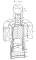
- Fig. 1 shows a magnetic refrigerator according to one embodiment of this invention.
- This magnetic refrigerator is used for helium cooling, and comprises a working material 1, a superconductive coil 2, a heat pipe 3, and a heat absorbing means 4 which are located above a reservoir 5 storing helium as the object to be cooled.
- the working material 1, the superconductive coil 2, the heat pipe 3, and the reservoir 5 are housed in a vacuum container (not shown) and kept in a vacuum.
- the reservoir 5 is in the form of a cylinder having top and bottom walls. Part of the helium is stored as liquid helium 6a in the reservoir 5, while the remaining part is hermetically kept as gaseous helium in the reservoir 5.
- the working material 1 is in the form of a cylinder, and is laid on a discoid bed plate 7 so that its longitudinal direction is vertical.
- the working material 1 is obtained by cutting a lump of magnetic material, such as gadolinium-gallium-garnet (GGG), an alloy of erbium and nickel, D Y3 A[ 5 0 12 , Gd 3 AI 5 0 12 , GdP0 4 , or Dy 2 Ti 2 0 l -After the cutting work, the resultant cylindrical body is preferably etched in an aqueous solution of phosphoric acid at approximately 160°C. By this etching process, a work distortion layer on the surface of the cylindrical body is removed to improve the thermal conductivity of the working material 1.
- the working material 1 radiates heat when magnetized and absorbs heat when demagnetized.
- the heat pipe 3 includes coaxial inner and outer cylinders 8 and 9.
- the inner cylinder 8 has the same outside diameter as the diameter of the working material 1.
- the upper end of the inner cylinder 8 is hermetically fixed to the peripheral edge of the bed plate 7.
- the outer cylinder 9 is disposed coaxially with the inner cylinder 8 so as to face the respective peripheral surfaces of the working material 1 and the inner cylinder 8 at a space of approximately 200 to 500 microns therefrom.
- Each of the lower ends of the outer and inner cylinders 9 and 8 is hermetically fixed to a ring-shaped bottom plate 11.
- a hat-shaped top plate 12 includes a projected central portion 12a in the center and a collar portion 12b around the same.
- the upper end of the outer cylinder 9 is hermetically fixed to the peripheral edge of the collar portion 12b. Part of the lower surface of the collar portion 12b is laid on the top face of the working material 1, and a sealing member 14 is interposed between them.
- An internal space 10 of the heat pipe 3 is defined in the region where the inner peripheral surface of the outer cylinder 9 faces the outer peripheral surface of the inner cylinder 8 and the peripheral surface of the working material 1.
- the internal space 10 is directly in contact with the peripheral surface of the working material 1 so that the latter functions as a condensing surface of the heat pipe 3.
- the internal space 10 is sealed up by the sealing member 14. Helium gas is sealed in the internal space 10, and liquid helium 6b exists at the bottom portion of the internal space 10.
- the lower portions of the inner and outer cylinders 8 and 9 are located in the internal space of the reservoir 5, penetrating a top plate 5a of the reservoir 5.
- the inner and outer cylinders 8 and 9 are hermetically fixed to the top plate 5a.
- a space 15 defined by the bed plate 7, the inner cylinder 8, and the top plate 5a is kept in a vacuum so that heat is-prevented from being transferred from the reservoir 5 to the working material 1.
- the top plate 12, the outer and inner cylinders 9 and 8, and the bed plate 7 are made of a nonmagnetic material or materials. Some of these members may be formed integrally. Alternatively, these may be manufactured by joining different materials together.
- the heat exchanging capability of the heat pipe 3 can be improved by forming those portions of the inner and outer cylinders 8 and 9 which are located inside the reservoir 5 from a material with high thermal conductivity and those portions of the cylinders 8 and 9 outside the reservoir 5 from a material with low thermal conductivity.
- the superconductive coil 2 is disposed concentrically with the working material 1 at a suitable distance from the outer cylinder 9 so as to surround the working material 1.
- the superconductive coil 2 is kept at a very low temperature, and is intermittently supplied with current from a suitable power source (not shown).
- a suitable power source not shown
- a cooling space 13 sealed by the sealing member 14 is defined between the central portion 12a of the top plate 12 and the top face of the working material 1.
- the heat absorbing means 4 to absorb heat from the working material 1 includes a miniature hydrogen refrigerator unit 16 located over the top plate 12.
- the hydrogen refrigerator unit 16 itself is a conventional type, and produces helium gas at a temperature of 20°K or below.
- the refrigerator unit 16 has an outlet pipe 17 for supplying the helium gas as a refrigerant and an inlet pipe 18 for returning the helium gas to the refrigerator unit 16.
- Valves 21 and 22 for switching are provided at the extreme ends of the outlet and inlet pipes 17 and 18, respectively. Pipes 19 and 20 connect the cooling space 13 inside the top plate 12 with the valves 21 and 22, respectively.
- a by-pass pipe 23 connects the outlet and inlet pipes 17 and 18, and a valve 24 for switching is disposed in the middle of the pipe 23.
- the valves 21 and 22 are closed while the valve 24 is open, then the helium gas from the refrigerator unit 16 circulates through the outlet pipe 17, the pipe 23, and the inlet pipe 18.
- the valves 21 and 22 are open while the valve 24 is closed, on the other hand, the helium gas from the refrigerator unit 16 circulates through the outlet pipe 17, pipe 19, cooling space 13, pipe 20, and inlet pipe 18.
- the heat of the working material 1 is extracted by the helium gas flowing through the cooling space 13. Accordingly, if the working material 1 generates heat, the generated heat is discharged through the medium of the helium gas to restrain the temperature of the working material 1 from rising.
- the superconductive coil 2 is energized, then the valves 21 and 22 are opened, and the valve 24 is closed.
- the working material 1 is adiabatically magnetized by the coil 2 to radiate heat. This heat is extracted from the top face of the working material 1 by the helium gas at 20°K or below flowing through the cooling space 13, and is discharged together with the helium gas. Thus, the temperature of the working material 1 is prevented from being increased by the adiabatic magnetization.
- the valve 24 is opened, the valves 21 and 22 are closed, and the current supply to the coil 2 is stopped.
- application of the magnetic field to the working material 1 is interrupted to adiabatically demagnetize the working material 1, so that the temperature of the working material 1 is lowered rapidly.
- the temperature of the working material 1 is lowered to the temperature of liquefaction of helium gas, i.e., 4.2°K or below, the helium gas in the internal space 10 of the heat pipe 3 is cooled to be liquefied, and condenses on the peripheral surface of the working material 1.
- Drops of the condensed liquid helium are cooled to a temperature below 4.2°K, and fall into the space 10 of the heat pipe 3 to be stored as the liquid helium 6b at the lower portion of the heat pipe 3.
- the helium gas in the reservoir 5 is cooled by that portion of the heat pipe 3 which is located inside the reservoir 5 and stores the liquid helium 6b.
- the helium gas in the reservoir 5 is cooled and liquefied, and condenses on the outer surface of the heat pipe 3 inside the reservoir 5. Drops of the condensed helium fall into the reservoir 5 to be stored therein as the liquid helium 6a. Accordingly, the helium gas in the helium reservoir 5 is cooled and liquefied by the heat pipe 3.
- heat is transferred in one direction from the reservoir 5 toward the working material 1 through the heat pipe 3.
- the superconductive coil 2 is energized, the valves 21 and 22 are opened, and the valve 24 is closed.
- the working material 1 is adiabatically magnetized by the coil 2, and is cooled by the heat absorbing means 4.
- the valve 24 is opened, the valves 21 and 22 are closed, and the current supply to the coil 2 is stopped.
- the working material 1 is adiabatically demagnetized and cooled rapidly.
- Heat is transmitted from the reservoir 5 to the working material 1 through the space 10 of the heat pipe 3.
- the adiabatic magnetization and demagnetization of the working material 1 are repeated, and the helium gas and the liquid helium 6a in the reservoir 5 as the objects for cooling are cooled.
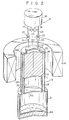
- FIG. 2 shows a magnetic refrigerator according to another embodiment of this invention.
- a heat pipe 3 of this second embodiment differs from the heat pipe 3 shown in Fig. 1 in that it communicates with the interior of a reservoir 5 as the object for cooling.
- the lower ends of outer and inner cylinders 26 and 25 of the heat pipe 3 are fixed to a top plate 5a of the reservoir 5.
- the inner cylinder 25 or the top plate 5a is supported by a suitable support means (not shown). Accordingly, an internal space 10 of the heat pipe 3 is connected to the internal space of the reservoir 5.
- helium gas or liquid helium 6a in the reservoir 5 is cooled by the same operation as in the embodiment shown in Fig. 1.
- the helium gas in the reservoir 5 as the object is cooled directly by the working material 1, so that the process of heat exchange between the heat transfer medium in the heat pipe 3 and the object is unnecessary.
- the refrigerating efficiency of the refrigerator can further be improved.
- a cylindrical block is cut from a lump of magnetic material, such as GGG (gadolinium-gallium-garnet, Gd 3GaIO12 ), D Y3 AI,0 121 Gd 3 A1 5 0 12 , GdP0 4 or Dy 2 Ti 2 0,, and its surface is lapped.
- This block is immersed in an aqueous solution of phosphoric acid kept at approximately 160°C, and is etched to be cleared of a surfaec layer with a thickness of approximately 50 to 60 microns. In this manner, a work distortion layer on the surface of the block can be removed easily and securely without complicating the manufacturing process.
- a working material for magnetic refrigeration with high thermal conductivity can be manufactured with ease.
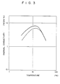
- Fig. 3 shows the temperature-induced variation of the thermal conductivity of the working material at very low temperature.
- a full line represents the thermal conductivity of a sample of the working material cleared of the surface work distortion layer by etching, while a broken line represents that of another sample only lapped.
- the thermal conductivity (full line) ofthe etched working material is much higherthan that (broken line) of the unetched working material especially in a temperature range of 20°K and below.
- the very-low-temperature refrigerating efficiency of the magnetic refrigerator may be improved by the use of the working material cleared of the surface work distortion layer.
- the heat absorbing means 4 is not limited to the construction of the aforementioned embodiments in which a refrigerant (helium gas) is circulated over the top face of the working material 1 for contact cooling.
- a refrigerant helium gas
- the magnetic refrigerator may use a heat pipe forthe heat absorbing means.
- the condensing section of the heat pipe 3 for cooling the helium gas in the reservoir 5 is provided at the lower half portion of the peripheral surface of the working material 1, while the evaporating section of the heat pipe of the heat absorbing means 4 is provided atthe upper half portion of the peripheral surface of the working material 1.
- the object for cooling is not limited to the gaseous body which was used in the foregoing embodiments.
- a solid object may be cooled by bringing it into contact with the lower end portion of the heat pipe 3 according to the first embodiment.
- the heat pipe 3 need not always be cylindrical.
- the heat pipe 3 need not always be so positioned as to extend vertically, and may be positioned in a slanting manner.
- the working material 1 is magnetized or demagnetized by energizing or deenergizing the superconductive coil 2.
- the working material 1 may be placed in or removed from a magnetic field by periodically moving the energized coil 2 in its axial direction.
- Various other means than the superconductive coil may be used for applying the magneticfield to the working material 1.
Landscapes
- Chemical & Material Sciences (AREA)
- Engineering & Computer Science (AREA)
- Ceramic Engineering (AREA)
- Organic Chemistry (AREA)
- Materials Engineering (AREA)
- Inorganic Chemistry (AREA)
- Physics & Mathematics (AREA)
- General Engineering & Computer Science (AREA)
- Thermal Sciences (AREA)
- Power Engineering (AREA)
- Mechanical Engineering (AREA)
- Structural Engineering (AREA)
- Containers, Films, And Cooling For Superconductive Devices (AREA)
Claims (8)
caractérisé en ce qu'il comprend:
Applications Claiming Priority (4)
| Application Number | Priority Date | Filing Date | Title |
|---|---|---|---|
| JP150903/82 | 1982-08-31 | ||
| JP57150939A JPS5941760A (ja) | 1982-08-31 | 1982-08-31 | 磁気冷凍装置 |
| JP150939/82 | 1982-08-31 | ||
| JP57150903A JPS5948800B2 (ja) | 1982-08-31 | 1982-08-31 | 磁気冷凍作業物質の製造方法 |
Related Child Applications (1)
| Application Number | Title | Priority Date | Filing Date |
|---|---|---|---|
| EP86117025.6 Division-Into | 1986-12-08 |
Publications (3)
| Publication Number | Publication Date |
|---|---|
| EP0104713A2 EP0104713A2 (fr) | 1984-04-04 |
| EP0104713A3 EP0104713A3 (en) | 1986-01-15 |
| EP0104713B1 true EP0104713B1 (fr) | 1988-07-27 |
Family
ID=26480342
Family Applications (2)
| Application Number | Title | Priority Date | Filing Date |
|---|---|---|---|
| EP83303090A Expired EP0104713B1 (fr) | 1982-08-31 | 1983-05-27 | Réfrigérateur magnétique |
| EP86117025A Expired - Lifetime EP0223265B1 (fr) | 1982-08-31 | 1983-05-27 | Procédé de fabrication de la matière de travail utilisée dans un réfrigérateur magnétique |
Family Applications After (1)
| Application Number | Title | Priority Date | Filing Date |
|---|---|---|---|
| EP86117025A Expired - Lifetime EP0223265B1 (fr) | 1982-08-31 | 1983-05-27 | Procédé de fabrication de la matière de travail utilisée dans un réfrigérateur magnétique |
Country Status (2)
| Country | Link |
|---|---|
| EP (2) | EP0104713B1 (fr) |
| DE (2) | DE3382670T2 (fr) |
Families Citing this family (9)
| Publication number | Priority date | Publication date | Assignee | Title |
|---|---|---|---|---|
| FR2574913B1 (fr) * | 1984-12-18 | 1987-01-09 | Commissariat Energie Atomique | Dispositif de refrigeration ou de pompage de chaleur |
| FR2869403A1 (fr) | 2004-04-23 | 2005-10-28 | Christian Muller | Dispositif et procede de generation de thermies a materiau magneto-calorique |
| DE102017009719A1 (de) | 2017-10-18 | 2018-04-19 | Daimler Ag | Ladeeinrichtung zum induktiven Laden eines Energiespeichers eines Kraftfahrzeugs mit elektrischer Energie |
| JP7125606B2 (ja) * | 2018-09-14 | 2022-08-25 | ダイキン工業株式会社 | 流体温度調節装置 |
| CN110207422A (zh) * | 2019-06-18 | 2019-09-06 | 胡家华 | 一种生物电磁场驱动的磁制冷系统 |
| CN111174460A (zh) * | 2020-01-13 | 2020-05-19 | 华南理工大学 | 应用于微元回热系统的强化传热结构及强化传热方法 |
| CN113429224B (zh) * | 2021-05-14 | 2022-10-04 | 中国工程物理研究院材料研究所 | 一种碳材料的表面刻蚀方法 |
| CN114634359B (zh) * | 2022-03-01 | 2023-01-31 | 中国科学院赣江创新研究院 | 一种磁制冷微球及其制备方法与应用 |
| CN114909818B (zh) * | 2022-07-18 | 2022-10-04 | 南方科技大学 | 一种用于核绝热去磁制冷系统中的锡制分合装置 |
Citations (2)
| Publication number | Priority date | Publication date | Assignee | Title |
|---|---|---|---|---|
| DE1521711A1 (de) * | 1966-08-19 | 1969-10-02 | Helmut Winkler | Verfahren zum Entgraten von gestanzten oder mit Schnittwerkzeugen bearbeiteten metallischen Werkstuecken |
| DE1771359A1 (de) * | 1968-05-11 | 1971-11-25 | Daimler Benz Ag | Verfahren und Vorrichtung zum Entgraten von Werkstuecken |
Family Cites Families (7)
| Publication number | Priority date | Publication date | Assignee | Title |
|---|---|---|---|---|
| US3125861A (en) * | 1964-03-24 | Method and apparatus for heat transfer | ||
| US2913881A (en) * | 1956-10-15 | 1959-11-24 | Ibm | Magnetic refrigerator having thermal valve means |
| US3393526A (en) * | 1966-06-29 | 1968-07-23 | Rca Corp | Cryogenic heat pump including magnetic means for moving a normal zone along a superconductive rod |
| US3598178A (en) * | 1969-05-26 | 1971-08-10 | Gen Electric | Heat pipe |
| CH519149A (de) * | 1970-07-28 | 1972-02-15 | Bbc Brown Boveri & Cie | Rohrofen |
| US3841107A (en) * | 1973-06-20 | 1974-10-15 | Us Navy | Magnetic refrigeration |
| US4332135A (en) * | 1981-01-27 | 1982-06-01 | The United States Of America As Respresented By The United States Department Of Energy | Active magnetic regenerator |
-
1983
- 1983-05-27 EP EP83303090A patent/EP0104713B1/fr not_active Expired
- 1983-05-27 DE DE8686117025T patent/DE3382670T2/de not_active Expired - Fee Related
- 1983-05-27 DE DE8383303090T patent/DE3377517D1/de not_active Expired
- 1983-05-27 EP EP86117025A patent/EP0223265B1/fr not_active Expired - Lifetime
Patent Citations (2)
| Publication number | Priority date | Publication date | Assignee | Title |
|---|---|---|---|---|
| DE1521711A1 (de) * | 1966-08-19 | 1969-10-02 | Helmut Winkler | Verfahren zum Entgraten von gestanzten oder mit Schnittwerkzeugen bearbeiteten metallischen Werkstuecken |
| DE1771359A1 (de) * | 1968-05-11 | 1971-11-25 | Daimler Benz Ag | Verfahren und Vorrichtung zum Entgraten von Werkstuecken |
Non-Patent Citations (1)
| Title |
|---|
| DUNN and REAY "Heat pipes". Pergamon Press 1978, p. 209-211 * |
Also Published As
| Publication number | Publication date |
|---|---|
| EP0104713A2 (fr) | 1984-04-04 |
| EP0223265A3 (en) | 1988-12-21 |
| DE3377517D1 (en) | 1988-09-01 |
| DE3382670D1 (de) | 1993-05-06 |
| EP0104713A3 (en) | 1986-01-15 |
| DE3382670T2 (de) | 1993-08-12 |
| EP0223265A2 (fr) | 1987-05-27 |
| EP0223265B1 (fr) | 1993-03-31 |
Similar Documents
| Publication | Publication Date | Title |
|---|---|---|
| US4509334A (en) | Magnetic refrigerator | |
| US4464903A (en) | Magnetic refrigerator | |
| US4033734A (en) | Continuous, noncyclic magnetic refrigerator and method | |
| US4457135A (en) | Magnetic refrigerating apparatus | |
| JPS60169065A (ja) | 磁気冷凍装置 | |
| JPH0332710B2 (fr) | ||
| EP0223265B1 (fr) | Procédé de fabrication de la matière de travail utilisée dans un réfrigérateur magnétique | |
| JP2513608B2 (ja) | 磁気冷凍方法および装置 | |
| EP1899659A1 (fr) | Systeme combine de refrigeration magnetique et thermo-electrique | |
| JPS60211273A (ja) | 磁気冷凍機 | |
| JPH084652A (ja) | クライオポンプ | |
| JP3310847B2 (ja) | 磁気冷凍装置 | |
| JPS5926205Y2 (ja) | 蓄冷熱交換器 | |
| JPH0663675B2 (ja) | 磁気冷凍装置 | |
| JPS5969669A (ja) | 磁気冷凍装置 | |
| JPH0371627B2 (fr) | ||
| JPS62299005A (ja) | 超電導マグネツト装置 | |
| JPS608672A (ja) | カスケ−ド型磁気冷凍機 | |
| JPS63129265A (ja) | 往復動型磁気冷凍装置 | |
| JPS5993158A (ja) | 磁気冷凍装置 | |
| JPH02254264A (ja) | 極低温蓄熱器 | |
| JPS63169463A (ja) | パルス超電導マグネツトの冷却装置 | |
| JPH0432305B2 (fr) | ||
| JPS5941759A (ja) | 磁気冷凍装置 | |
| JPH0519062B2 (fr) |
Legal Events
| Date | Code | Title | Description |
|---|---|---|---|
| PUAI | Public reference made under article 153(3) epc to a published international application that has entered the european phase |
Free format text: ORIGINAL CODE: 0009012 |
|
| 17P | Request for examination filed |
Effective date: 19830606 |
|
| AK | Designated contracting states |
Designated state(s): CH DE FR GB LI NL |
|
| RAP1 | Party data changed (applicant data changed or rights of an application transferred) |
Owner name: KABUSHIKI KAISHA TOSHIBA |
|
| PUAL | Search report despatched |
Free format text: ORIGINAL CODE: 0009013 |
|
| AK | Designated contracting states |
Designated state(s): CH DE FR GB LI NL |
|
| 17Q | First examination report despatched |
Effective date: 19860521 |
|
| R17C | First examination report despatched (corrected) |
Effective date: 19870126 |
|
| GRAA | (expected) grant |
Free format text: ORIGINAL CODE: 0009210 |
|
| AK | Designated contracting states |
Kind code of ref document: B1 Designated state(s): DE FR GB |
|
| REF | Corresponds to: |
Ref document number: 3377517 Country of ref document: DE Date of ref document: 19880901 |
|
| ET | Fr: translation filed | ||
| PLBE | No opposition filed within time limit |
Free format text: ORIGINAL CODE: 0009261 |
|
| STAA | Information on the status of an ep patent application or granted ep patent |
Free format text: STATUS: NO OPPOSITION FILED WITHIN TIME LIMIT |
|
| 26N | No opposition filed | ||
| PGFP | Annual fee paid to national office [announced via postgrant information from national office to epo] |
Ref country code: FR Payment date: 19930510 Year of fee payment: 11 |
|
| PGFP | Annual fee paid to national office [announced via postgrant information from national office to epo] |
Ref country code: GB Payment date: 19930514 Year of fee payment: 11 |
|
| PGFP | Annual fee paid to national office [announced via postgrant information from national office to epo] |
Ref country code: DE Payment date: 19930602 Year of fee payment: 11 |
|
| PG25 | Lapsed in a contracting state [announced via postgrant information from national office to epo] |
Ref country code: GB Effective date: 19940527 |
|
| GBPC | Gb: european patent ceased through non-payment of renewal fee |
Effective date: 19940527 |
|
| PG25 | Lapsed in a contracting state [announced via postgrant information from national office to epo] |
Ref country code: FR Effective date: 19950131 |
|
| PG25 | Lapsed in a contracting state [announced via postgrant information from national office to epo] |
Ref country code: DE Effective date: 19950201 |
|
| REG | Reference to a national code |
Ref country code: FR Ref legal event code: ST |