EP0104882A1 - Montageanordnungen zum Verbinden einer optischen Faser - Google Patents
Montageanordnungen zum Verbinden einer optischen Faser Download PDFInfo
- Publication number
- EP0104882A1 EP0104882A1 EP83305576A EP83305576A EP0104882A1 EP 0104882 A1 EP0104882 A1 EP 0104882A1 EP 83305576 A EP83305576 A EP 83305576A EP 83305576 A EP83305576 A EP 83305576A EP 0104882 A1 EP0104882 A1 EP 0104882A1
- Authority
- EP
- European Patent Office
- Prior art keywords
- ferrule
- housing
- boss
- metal
- wall
- Prior art date
- Legal status (The legal status is an assumption and is not a legal conclusion. Google has not performed a legal analysis and makes no representation as to the accuracy of the status listed.)
- Granted
Links
Images
Classifications
-
- G—PHYSICS
- G02—OPTICS
- G02B—OPTICAL ELEMENTS, SYSTEMS OR APPARATUS
- G02B6/00—Light guides; Structural details of arrangements comprising light guides and other optical elements, e.g. couplings
- G02B6/24—Coupling light guides
- G02B6/42—Coupling light guides with opto-electronic elements
- G02B6/4201—Packages, e.g. shape, construction, internal or external details
- G02B6/4202—Packages, e.g. shape, construction, internal or external details for coupling an active element with fibres without intermediate optical elements, e.g. fibres with plane ends, fibres with shaped ends, bundles
-
- G—PHYSICS
- G02—OPTICS
- G02B—OPTICAL ELEMENTS, SYSTEMS OR APPARATUS
- G02B6/00—Light guides; Structural details of arrangements comprising light guides and other optical elements, e.g. couplings
- G02B6/24—Coupling light guides
- G02B6/42—Coupling light guides with opto-electronic elements
- G02B6/4201—Packages, e.g. shape, construction, internal or external details
- G02B6/4219—Mechanical fixtures for holding or positioning the elements relative to each other in the couplings; Alignment methods for the elements, e.g. measuring or observing methods especially used therefor
- G02B6/4236—Fixing or mounting methods of the aligned elements
-
- G—PHYSICS
- G02—OPTICS
- G02B—OPTICAL ELEMENTS, SYSTEMS OR APPARATUS
- G02B6/00—Light guides; Structural details of arrangements comprising light guides and other optical elements, e.g. couplings
- G02B6/24—Coupling light guides
- G02B6/42—Coupling light guides with opto-electronic elements
- G02B6/4201—Packages, e.g. shape, construction, internal or external details
- G02B6/4248—Feed-through connections for the hermetical passage of fibres through a package wall
-
- G—PHYSICS
- G02—OPTICS
- G02B—OPTICAL ELEMENTS, SYSTEMS OR APPARATUS
- G02B6/00—Light guides; Structural details of arrangements comprising light guides and other optical elements, e.g. couplings
- G02B6/24—Coupling light guides
- G02B6/42—Coupling light guides with opto-electronic elements
- G02B6/4201—Packages, e.g. shape, construction, internal or external details
- G02B6/4219—Mechanical fixtures for holding or positioning the elements relative to each other in the couplings; Alignment methods for the elements, e.g. measuring or observing methods especially used therefor
- G02B6/4236—Fixing or mounting methods of the aligned elements
- G02B6/4238—Soldering
Definitions
- This invention relates to an optical coupling assembly in which an optical fibre is coupled to an opto-electronic device, for example a light source such as a semiconductor junction laser or a light emitting diode, or a light receiving device such as a photodiode, and wherein the interface between the optical fibre and the opto-electronic device is located in an enclosed space.
- an opto-electronic device for example a light source such as a semiconductor junction laser or a light emitting diode, or a light receiving device such as a photodiode
- the invention also relates to methods of manufacturing the assembly described.
- optical fibre and the opto-electronic device are accurately and fixedly aligned in both radial and axial directions, particularly high precision of alignment being required in the case of a monomode optical fibre; moreover, such alignment should be maintained constant over a range of ambient temperatures, for example -20°C to +60°C. It is further required that the space in which the interface between the fibre and the device is situated is hermetically sealed against the ingress of moisture or dust.
- an optical coupling assembly comprising a metal housing forming an enclosure and having a front wall provided with an aperture and an integral external boss formed around the ; aperture, which boss has a central bore extending from the said aperture orthogonally to the front wall, an opto-.
- the optical fibre is preferably sealed into the ferrule by means of solder, the fibre first being coated with metal, suitably gold, either by thermal decomposition of an organo-metallic compound, or with nickel-chromium-gold by conventional vapour phase deposition techniques. Precision jigging facilities are employed to position the fibre centrally along the axis of the ferrule, in order to minimise differential expansion effects.
- the opto-electronic device mounted within the housing is a semiconductor junction laser
- light receiving means for example a photodiode or an optical fibre
- the monitoring means is connected to means for automatically adjusting and stabilising the output of the laser in response to variations in the light received by the monitor.
- the glass-to-metal seal by means of which the lead to the opto-electronic device is passed through the wall of the housing consists of a metal rod sealed through a glass bead or disc, which is sealed into an additional aperture in the housing wall, preferably the front wall.
- the glass may be sealed directly to the housing wall around the aperture, but preferably the glass body is surrounded.by, and sealed into, a metal sheath which is soldered to the wall, the sheath being formed of the same metal as the rod and the housing.
- the lead wire connected to the opto-electronic device is soldered to the end of the rod located within the housing, and a further length of lead wire, as required, may be soldered to the external end of the rod.
- the uniform metal components of the assembly namely the housing, header, ferrule, device lead, and metal part or parts of the glass-to-metal seal, are suitably composed of copper, most of the components preferably being gold-plated.
- the screws inserted into the boss are preferably formed of a metal which is not wetted by the solder used for bonding the ferrule to the boss, and which has thermal expansion characteristics substantially matching those of the metal of the other components. Where the latter are formed of copper, the boss screws are suitably formed of chromium-plated copper or of a stainless steel having the required expansion characteristics.
- a preferred method of manufacturing the optical coupling assembly in accordance with the invention includes the steps of sealing the said glass-to-metal seal into the front wall of the housing, attaching the header, with the opto-electronic device mounted thereon, to the interior surface of the front wall of the housing, soldering the lead of the said device to the metal rod component of the glass-to-metal seal, sealing the optical fibre into the ferrule by means of a first solder, inserting the ferrule-fibre assembly into the boss on the front wall of the housing, aligning the fibre with the opto-electronic device and clamping the ferrule in the aligned position by means of the screws inserted through the wall of the boss, soldering the ferrule to the interior surface of the boss wall by means of a second solder having a lower melting point than that of said first solder, and sealing the said cover portion to the front wall of the housing.
- a metal-sheathed glass-to-metal seal may be soldered into the housing wall, suitably using the said first solder employed for soldering the optical fibre into the ferrule: the soldering temperature employed is not critical for either of these operations.
- the header may be fixed to the front wall of the housing by means of screws and/or solder. If solder is used for this step, and for previously sealing the glass-to-metal seal into the housing wall, the solder used for the header should have a lower melting point than that used for the glass-to-metal seal.
- the soldering of the lead of the opto-electronic device to the metal rod is conveniently effected by means of a soldering iron, the temperature of this operation again being noncritical since it involves only local heating.
- a gold-plated optical fibre can be bonded directly to the interior surface of a gold-plated copper ferrule by solder filling the space around the fibre in the i interior of the ferrule.
- the gold-plated fibre may have copper electro-deposited upon it to a sufficient thickness to fill the interior of the ferrule, the fibre so coated is then inserted into the ferrule, and the copper coating is soldered to both ends of the ferrule.
- the opto-electronic device For aligning the optical fibre with the opto-electronic device, where the latter is a light source, the light output from the remote end of the fibre, when the light source is operated, is monitored while the position of the ferrule within the boss is adjusted by means of a micromanipulator and/or the boss screws, the attainment of maximum light output indicating correct positioning of the ferrule and fibre.
- the opto-electronic device is a photodiode
- alignment is effected in a similar manner by passing light through the fibre and monitoring the resulting electrical output of the photodiode.
- the cover portion and front wall of the housing may be sealed together by soldering.
- this step and the step of soldering the ferrule to the interior surface of the boss wall are carried out simultaneously, the said second solder being employed for both operations.
- the solder employed for joining the housing components must have a lower melting point than that of the said second solder.
- the housing components may be joined by spot welding or pressure welding.
- a light-receiving monitor When it is required to incorporate a light-receiving monitor into the back wall of the housing, this is sealed into the aperture in the back wall before the cover is sealed to the front wall of the housing.
- the monitor employed is a photodiode, it may be sealed into the wall by spot welding or by soldering at a temperature sufficiently low to avoid damaging the photodiode.
- An optical fibre monitor is first soldered into a ferrule, suitably using said first solder, and the ferrule is then soldered into a boss extending from the back wall in a similar manner to the front wall boss, using a solder of lower melting point than that employed for soldering the monitor fibre into its ferrule.
- solder for bonding together all the external components of the assembly, including its use for the optical fibre-to-ferrule and ferrule-to-boss joints, is advantageous in that it ensures that the coupling between the optical fibre and the opto-electronic device is hermetically sealed within the housing.
- a cascade soldering process is used in the construction of the assembly, that is to say successive soldering steps in the assembling of the various components together are carried out at successively lower temperatures, so that each step is effected without risk of damage to the soldered joints formed in previous steps.
- a further advantage of the assembly of the invention is that, since all the metal parts, with the exception of the ferrule-clamping screws inserted into the boss, are constructed of the same metal, the whole assembly can be heated as required for soldering operations, with no risk of differential expansion of the components. Furthermore, since the optical fibre and the opto-electronic.device are both mounted on the front wall of the housing, and since the housing, ferrule and device header are all formed of the same metal, the correct alignment between the fibre and the device is maintained under all operating conditions, over a wide range of ambient temperatures.
- the screws provided in the front wall boss have the advantage that they clamp the ferrule firmly in position while the solder used for bonding the ferrule to the boss is solidifying and cooling, thus preventing any distortion of the ferrule-boss assembly which might otherwise ensue. If, as is preferred, the screws are not wetted by the solder, they can, if required, be used after soldering for minor adjustment of the position of the ferrule, and hence of the fibre, by deformation of the solder.
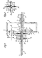
- the assembly shown in the drawings constitutes a hermetically sealed coupling between a monomode optical fibre 1 and a semiconductor junction laser 2.
- the assembly housing consists of a front wall portion 3 with an outwardly extending boss 4 formed around an aperture 5, and a cover 6 with an outwardly extending boss 7 formed around an aperture 8. in the back wall.
- the housing is suitably of rectangular cross-section (but could be circular), and is entirely formed of gold-plated copper; the front wall and cover are soldered together at 9.
- the optical fibre 1 is soldered into a gold-plated copper ferrule 10, which is itself soldered into the bore of boss 4 and is clamped by two parallel sets of four screws each, lla and llb, inserted through the boss 4: one set of screws, lla, is shown in Figure 2.
- the screws are composed, for example, of 18% chromium-8% nickel stainless steel (British Standard Specification EN58B).
- the ferrule 10 has an elongated integral extension 12, for use in the fibre alignment procedure as will be described below.
- the fibre 1 extends beyond the inner end of the ferrule 10 through the aperture 5, so as to be coupled with the laser 2, which is located substantially opposite to the centre of the aperture 5 and is mounted in a recess 13 at the upper end of a gold-plated copper header 14 which is attached to the front wall 3 of the housing by copper screws 15.
- the laser is provided with a copper wire lead 16 the ends of which are soldered respectively to the header 14 and to a gold-plated copper rod 17, which is sealed into an aperture 18 in the front housing wall 3 by means of a glass-to-metal seal structure consisting of the rod 17, a glass bead 19, and a gold-plated copper sheath 20 soldered to the housing wall.
- a multimode optical fibre 21 having a large numerical aperture, for example 0.2, is sealed through the boss ? on the back wall of the housing.
- the fibre 21 is sealed into a gold-plated copper ferrule 22, which is soldered into the boss 7 in such a position that the end of the fibre 21 is located as close as possible to the laser 2.
- the remote end of the fibre 21 is coupled to a photodiode (not shown in the drawings) which is connected to means (not shown) for adjusting the laser output in response to the intensity of the light received by the photodiode via the fibre 21.
- the front housing wall assembly is first completed by soldering the glass-to-metal seal into the aperture 18, and screwing the header 14, to which the laser 2 and lead wire 16 have previously been attached, to the inside of the front wall; the lead 16 is then soldered to the rod 17 with a soldering iron.
- solder 26 having a lower melting point than the solder 23/24/25: a suitable solder consists of the lead-tin eutectic melting nominally at 130°C: the soldering operation is carried out at 180°C.
- the ferrule 10 is then inserted into the boss 4 so that the tip of the fibre 1 comes into contact with the laser 2, and the fibre is aligned with the laser junction by means of a micro-manipulator (not shown) on the stage of which the end of the ferrule extension 12 is supported for this purpose, the light output from the remote end of the fibre being monitored until a maximum is attained.
- the ferrule 10 is then clamped in position by the screws lla and llb.
- the clamped ferrule is soldered to the interior surface of the boss 4 by solder 2?, the liquid solder being introduced through a hole 28 in the boss, and at the same time the housing cover 6 is soldered to the front wall 3 by means of a pre-formed gasket of .solder 9, of the same composition as solder 27.
- solder 2? the liquid solder being introduced through a hole 28 in the boss
- the housing cover 6 is soldered to the front wall 3 by means of a pre-formed gasket of .solder 9, of the same composition as solder 27.
- the assembly construction specifically described above may be modified, if desired, by locating the glass-to-metal seal on the opposite side of the boss 4 from the position shown in Figure 1, adjacent to the header 14, thus enabling the housing to be reduced in size.
Landscapes
- Physics & Mathematics (AREA)
- General Physics & Mathematics (AREA)
- Optics & Photonics (AREA)
- Optical Couplings Of Light Guides (AREA)
Applications Claiming Priority (2)
| Application Number | Priority Date | Filing Date | Title |
|---|---|---|---|
| GB8227799 | 1982-09-29 | ||
| GB8227799 | 1982-09-29 |
Publications (2)
| Publication Number | Publication Date |
|---|---|
| EP0104882A1 true EP0104882A1 (de) | 1984-04-04 |
| EP0104882B1 EP0104882B1 (de) | 1986-08-27 |
Family
ID=10533252
Family Applications (1)
| Application Number | Title | Priority Date | Filing Date |
|---|---|---|---|
| EP83305576A Expired EP0104882B1 (de) | 1982-09-29 | 1983-09-21 | Montageanordnungen zum Verbinden einer optischen Faser |
Country Status (5)
| Country | Link |
|---|---|
| US (1) | US4548466A (de) |
| EP (1) | EP0104882B1 (de) |
| JP (1) | JPS59135415A (de) |
| DE (1) | DE3365682D1 (de) |
| GB (1) | GB2127990B (de) |
Cited By (6)
| Publication number | Priority date | Publication date | Assignee | Title |
|---|---|---|---|---|
| EP0137485A3 (de) * | 1983-10-12 | 1985-05-15 | Siemens Aktiengesellschaft | |
| FR2573220A1 (fr) * | 1984-11-13 | 1986-05-16 | Cit Alcatel | Source optique |
| EP0165837B1 (de) * | 1984-05-11 | 1990-07-11 | RADIALL INDUSTRIE, Société Anonyme dite: | Verfahren zur mechanischen Sperrung eines inneren Elementes in einem äusseren Körper und Anwendung dieses Verfahrens zur Herstellung eines Verbindungsstückes für optische Fasern |
| EP0404053A3 (de) * | 1989-06-19 | 1991-01-09 | Fujitsu Limited | Optischer Halbleitermodul |
| FR2655161A1 (fr) * | 1989-11-30 | 1991-05-31 | Cit Alcatel | Dispositif a double couplage optique, notamment pour systeme de transmission a fibres optiques. |
| US5682451A (en) * | 1995-05-23 | 1997-10-28 | Minnesota Mining And Manufacturing Company | Device with internal features for rotational alignment of non-cylindrically symmetrical optical elements |
Families Citing this family (38)
| Publication number | Priority date | Publication date | Assignee | Title |
|---|---|---|---|---|
| DE3338315A1 (de) * | 1983-10-21 | 1985-05-02 | Standard Elektrik Lorenz Ag, 7000 Stuttgart | Optoelektrische koppelanordnung |
| US4832251A (en) * | 1983-12-13 | 1989-05-23 | General Electric Company | Method of mounting semiconductor lasers providing improved lasing spot alignment |
| DE3405805A1 (de) * | 1984-02-17 | 1985-08-22 | Siemens AG, 1000 Berlin und 8000 München | Schutzrohranordnung fuer glasfaser |
| US4699456A (en) * | 1985-05-01 | 1987-10-13 | American Telephone And Telegraph Company, At&T Bell Laboratories | Hermetic fiber seal |
| FR2588380B1 (fr) * | 1985-10-07 | 1988-05-27 | Commissariat Energie Atomique | Dispositif d'examen a distance de defauts debouchant a la surface interne d'une cavite profonde |
| CA1276451C (en) * | 1986-02-27 | 1990-11-20 | Neal Henry Thorsten | Techniques and apparatus for aligning a light emitter within its package |
| EP0241669A1 (de) * | 1986-03-12 | 1987-10-21 | Siemens Aktiengesellschaft | Verfahren zum Befestigen und Justieren eines Endabschnittes einer Glasfaser |
| JPS62248280A (ja) * | 1986-04-21 | 1987-10-29 | Nec Corp | レ−ザダイオ−ドモジユ−ルの光フアイバ固定構造 |
| DE3727092C1 (de) * | 1987-08-14 | 1988-11-10 | Wieland Elek Sche Ind Gmbh F | Lichtleiteranschlussklemme |
| DK158169C (da) * | 1987-08-31 | 1990-09-03 | Dantec Elektronik Med | Indkoblingsmanipulator for laserlys til en optisk fiber |
| US4840450A (en) * | 1988-02-03 | 1989-06-20 | General Electric Company | Apparatus and method for optical fiber end positioning for laser injection |
| EP0337141A1 (de) * | 1988-03-31 | 1989-10-18 | Siemens Aktiengesellschaft | Lichtwellenleiter-Durchführung für optoelektronische Module und Verfahren zu ihrer Herstellung |
| FR2668267B1 (fr) * | 1990-10-19 | 1992-12-11 | Thomson Hybrides | Procede d'alignement des axes optiques d'une fibre et d'un composant optoelectronique, et dispositif obtenu par ce procede. |
| JP2763016B2 (ja) * | 1991-12-25 | 1998-06-11 | 日本電気株式会社 | 光学素子基板の実装構造 |
| GB2268813B (en) * | 1992-07-13 | 1995-04-19 | Integrated Optical Components | Packaged optical devices |
| US5522003A (en) * | 1993-03-02 | 1996-05-28 | Ward; Robert M. | Glass preform with deep radial gradient layer and method of manufacturing same |
| US6345025B1 (en) | 1993-04-12 | 2002-02-05 | Olympus Optical Co., Ltd. | Apparatus for recording and/or reproducing information and/or from optical information record disk |
| JPH06301984A (ja) | 1993-04-12 | 1994-10-28 | Olympus Optical Co Ltd | 光学的情報記録及び/又は再生装置 |
| USRE40150E1 (en) | 1994-04-25 | 2008-03-11 | Matsushita Electric Industrial Co., Ltd. | Fiber optic module |
| US5546281A (en) * | 1995-01-13 | 1996-08-13 | Methode Electronics, Inc. | Removable optoelectronic transceiver module with potting box |
| US6220878B1 (en) | 1995-10-04 | 2001-04-24 | Methode Electronics, Inc. | Optoelectronic module with grounding means |
| US5717533A (en) | 1995-01-13 | 1998-02-10 | Methode Electronics Inc. | Removable optoelectronic module |
| IT1274365B (it) * | 1995-03-27 | 1997-07-17 | Alcatel Italia | Sistema di connessione tra una piastra a circuito stampato e un cavo e bussola per l'uso in detto sistema di connessione |
| US6203333B1 (en) | 1998-04-22 | 2001-03-20 | Stratos Lightwave, Inc. | High speed interface converter module |
| US6179627B1 (en) | 1998-04-22 | 2001-01-30 | Stratos Lightwave, Inc. | High speed interface converter module |
| US7090509B1 (en) | 1999-06-11 | 2006-08-15 | Stratos International, Inc. | Multi-port pluggable transceiver (MPPT) with multiple LC duplex optical receptacles |
| US6220873B1 (en) * | 1999-08-10 | 2001-04-24 | Stratos Lightwave, Inc. | Modified contact traces for interface converter |
| US6427046B1 (en) * | 2000-03-30 | 2002-07-30 | Schlumberger Technology Corporation | Optical feedthrough and method of making same |
| US20020179683A1 (en) * | 2001-06-01 | 2002-12-05 | Carrier Geary R. | Hermetic optical fiber seal |
| JP2003066284A (ja) * | 2001-08-23 | 2003-03-05 | Sumitomo Metal Mining Co Ltd | 光アイソレータモジュール |
| US7430081B2 (en) * | 2002-02-28 | 2008-09-30 | Emcore Corporation | Sub-micron adjustable mount for supporting a component and method |
| US7126078B2 (en) | 2002-02-28 | 2006-10-24 | Emcore Corporation | Sub-micron adjustable mount for supporting a component and method |
| US20040047571A1 (en) * | 2002-09-06 | 2004-03-11 | Boord Warren Timothy | Hermetically sealed ferrule |
| GB2398391A (en) * | 2003-02-15 | 2004-08-18 | Agilent Technologies Inc | Connecting optic fibre to active component using two plates |
| US6896421B2 (en) * | 2003-02-26 | 2005-05-24 | Lockheed Martin Corporation | Method and apparatus for assembly of an optoelectronic device with an optical connector |
| US7035521B2 (en) | 2003-08-13 | 2006-04-25 | Lockheed Martin Corporation | Method and apparatus for the integration of a VCSEL flex with a parallel optical transceiver package |
| DE102005000925A1 (de) * | 2005-01-07 | 2006-07-20 | Infineon Technologies Fiber Optics Gmbh | Bauteil und Verfahren zur exzentrischen Ausrichtung eines ersten und eines zweiten Stifts, die jeweils eine Lichtleitfaser zentrisch enthalten, sowie Modulvorsatz und Steckerkopplung mit meinem solchen Bauteil |
| JP6253255B2 (ja) | 2013-05-21 | 2017-12-27 | 株式会社ミツトヨ | 光源ユニット |
Citations (3)
| Publication number | Priority date | Publication date | Assignee | Title |
|---|---|---|---|---|
| US3954338A (en) * | 1973-09-06 | 1976-05-04 | Plessey Handel Und Investments A.G. | Mounting of optical fibres or other filaments in axial alignment with one another or with other elements |
| US4119363A (en) * | 1976-03-18 | 1978-10-10 | Bell Telephone Laboratories Incorporated | Package for optical devices including optical fiber-to-metal hermetic seal |
| US4346294A (en) * | 1979-07-05 | 1982-08-24 | Burr-Brown Research Corp. | Low profile optical coupling to planar-mounted optoelectronic device |
Family Cites Families (14)
| Publication number | Priority date | Publication date | Assignee | Title |
|---|---|---|---|---|
| FR2312789A1 (fr) * | 1975-05-27 | 1976-12-24 | Lenoane Georges | Connecteur pour diode a effet laser dans un systeme de transmission par fibres optiques |
| GB1541495A (en) * | 1976-05-27 | 1979-03-07 | Standard Telephones Cables Ltd | Coupling optical fibres to optical devices |
| US4357072A (en) * | 1978-01-28 | 1982-11-02 | Plessey Handel Und Investments Ag | Sealing optical fibres into packages |
| NL7802231A (nl) * | 1978-03-01 | 1979-09-04 | Tekade Felten & Guilleaume | Contrastekker met een lichtdetektor voor een losneemba- re stekkerverbinding voor het koppelen van een lichtge- leidende vezel aan een halfgeleiderlichtbron. |
| NL7802230A (nl) * | 1978-03-01 | 1979-09-04 | Tekade Felten & Guilleaume | Losneembare stekkerverbinding, alsmede stekker en con- trastekker voor het koppelen van een lichtgeleidende vezel aan een verdere lichtgeleidende vezel of aan een lichtbron/detektor. |
| US4167744A (en) * | 1978-03-23 | 1979-09-11 | Rca Corporation | Electroluminescent semiconductor device having optical fiber window |
| JPS54163046A (en) * | 1978-06-15 | 1979-12-25 | Oki Electric Ind Co Ltd | Production of photo coupler |
| GB2026194A (en) * | 1978-07-24 | 1980-01-30 | Gen Electric Co Ltd | Optical fibre coupling |
| FR2448727A1 (fr) * | 1979-02-08 | 1980-09-05 | Thomson Csf | Tete de couplage opto-electronique |
| DE2923490C2 (de) * | 1979-06-09 | 1982-04-29 | Standard Elektrik Lorenz Ag, 7000 Stuttgart | Stecker für Lichtleitungsverbinder |
| NL7908536A (nl) * | 1979-11-23 | 1981-06-16 | Philips Nv | Omhulling voor een fotodiode. |
| US4296998A (en) * | 1979-12-17 | 1981-10-27 | Bell Telephone Laboratories, Incorporated | Encapsulated light source with coupled fiberguide |
| JPS56113110A (en) * | 1980-02-13 | 1981-09-05 | Hitachi Ltd | Hermetic sealing method of light emission element package provided with optical fiber |
| FR2492542A1 (fr) * | 1980-09-23 | 1982-04-23 | Thomson Csf | Procede d'alignement d'une fibre de verre faisant partie d'un cable de transmission optique avec un composant opto-electronique, adaptateur, et tete de couplage comportant l'utilisation du procede |
-
1983
- 1983-09-21 GB GB08325272A patent/GB2127990B/en not_active Expired
- 1983-09-21 EP EP83305576A patent/EP0104882B1/de not_active Expired
- 1983-09-21 DE DE8383305576T patent/DE3365682D1/de not_active Expired
- 1983-09-29 JP JP58179435A patent/JPS59135415A/ja active Pending
- 1983-09-29 US US06/536,997 patent/US4548466A/en not_active Expired - Fee Related
Patent Citations (3)
| Publication number | Priority date | Publication date | Assignee | Title |
|---|---|---|---|---|
| US3954338A (en) * | 1973-09-06 | 1976-05-04 | Plessey Handel Und Investments A.G. | Mounting of optical fibres or other filaments in axial alignment with one another or with other elements |
| US4119363A (en) * | 1976-03-18 | 1978-10-10 | Bell Telephone Laboratories Incorporated | Package for optical devices including optical fiber-to-metal hermetic seal |
| US4346294A (en) * | 1979-07-05 | 1982-08-24 | Burr-Brown Research Corp. | Low profile optical coupling to planar-mounted optoelectronic device |
Non-Patent Citations (1)
| Title |
|---|
| PATENTS ABSTRACTS OF JAPAN, vol. 4, no. 24 (E-173), 29th Fevruary 1980, page 166 E 173 & JP - A - 54 163 046 (OKI DENKI KOGYO K.K.) 25-12-1979 * |
Cited By (12)
| Publication number | Priority date | Publication date | Assignee | Title |
|---|---|---|---|---|
| EP0137485A3 (de) * | 1983-10-12 | 1985-05-15 | Siemens Aktiengesellschaft | |
| US4707066A (en) * | 1983-10-12 | 1987-11-17 | Siemens Aktiengesellschaft | Glass fiber bushing through a wall opening of a housing and method of manufacture |
| EP0165837B1 (de) * | 1984-05-11 | 1990-07-11 | RADIALL INDUSTRIE, Société Anonyme dite: | Verfahren zur mechanischen Sperrung eines inneren Elementes in einem äusseren Körper und Anwendung dieses Verfahrens zur Herstellung eines Verbindungsstückes für optische Fasern |
| FR2573220A1 (fr) * | 1984-11-13 | 1986-05-16 | Cit Alcatel | Source optique |
| EP0183124A1 (de) * | 1984-11-13 | 1986-06-04 | Alcatel Cit | Optische Lichtquelle |
| US4701013A (en) * | 1984-11-13 | 1987-10-20 | Compagnie Industrielle Des Telecommunications | Optical source with optical fiber carrier |
| EP0404053A3 (de) * | 1989-06-19 | 1991-01-09 | Fujitsu Limited | Optischer Halbleitermodul |
| FR2655161A1 (fr) * | 1989-11-30 | 1991-05-31 | Cit Alcatel | Dispositif a double couplage optique, notamment pour systeme de transmission a fibres optiques. |
| EP0430124A1 (de) * | 1989-11-30 | 1991-06-05 | Alcatel Cit | Optisch doppelgekuppelte Vorrichtung, insbesondere für optisches Faserübertragungssystem |
| US5101464A (en) * | 1989-11-30 | 1992-03-31 | Alcatel Cit | Device providing two optical couplings, in particular for an optical fiber transmission system |
| AU631470B2 (en) * | 1989-11-30 | 1992-11-26 | Societe Anonyme Dite Alcatel Cit | A device providing two optical couplings, in particular for an optical fiber transmission system |
| US5682451A (en) * | 1995-05-23 | 1997-10-28 | Minnesota Mining And Manufacturing Company | Device with internal features for rotational alignment of non-cylindrically symmetrical optical elements |
Also Published As
| Publication number | Publication date |
|---|---|
| DE3365682D1 (en) | 1986-10-02 |
| GB8325272D0 (en) | 1983-10-26 |
| GB2127990B (en) | 1986-05-14 |
| US4548466A (en) | 1985-10-22 |
| EP0104882B1 (de) | 1986-08-27 |
| GB2127990A (en) | 1984-04-18 |
| JPS59135415A (ja) | 1984-08-03 |
Similar Documents
| Publication | Publication Date | Title |
|---|---|---|
| EP0104882B1 (de) | Montageanordnungen zum Verbinden einer optischen Faser | |
| US4615031A (en) | Injection laser packages | |
| CA1085663A (en) | Package for optical devices including optical fiber- to-metal hermetic seal | |
| US5692086A (en) | Optical fiber locking submount and hermetic feedthrough assembly | |
| US6092935A (en) | Optoelectronic transmitting and/or receiving module and method for its production | |
| EP0100086A2 (de) | Verfahren zur Herstellung von Einkapselungen von Laserdioden und Einkapselungen, die nach einem solchen Verfahren hergestellt sind | |
| US4708429A (en) | Optical fiber assembly and optically coupled device package including same | |
| KR0151717B1 (ko) | 광전송 섬유와 반도체 레이저 다이오드 사이에 커플링을 갖는 광전자 장치 | |
| US4752109A (en) | Optoelectronics package for a semiconductor laser | |
| EP0221180B1 (de) | Hermetische faserdichtung | |
| US4834490A (en) | Transmitting receiving device with a diode mounted on a support | |
| US4168883A (en) | Arrangement to connect a laser to an optical fiber transmission line | |
| JPS59113408A (ja) | 電子光学情報伝送装置用の送信又は受信のための装置 | |
| US5029968A (en) | Optoelectronic hybrid package assembly including integral, self-aligned fiber optic connector | |
| EP0259018B1 (de) | Optoelektronische Verpackungseinheit für einen Halbleiterlaser | |
| JPH0815572A (ja) | 光ファイバ導入部の気密封止構造と気密封止方法 | |
| US4818053A (en) | Optical bench for a semiconductor laser and method | |
| JPH01284807A (ja) | 光ファイバ貫通部とその製造方法 | |
| US20010033729A1 (en) | Hermetically sealed optical fiber assembly and method of manufacturing the same | |
| US4741589A (en) | Coupler for optical waveguides | |
| US4997279A (en) | Optical bench for a semiconductor laser and method | |
| GB2229856A (en) | Electro-optic transducer and sheet-metal microlens holder | |
| JP2508515B2 (ja) | 光フアイバの取付方法 | |
| JPH04128812A (ja) | 光半導体モジュールの組立方法 | |
| JPH0637368Y2 (ja) | 光半導体結合器 |
Legal Events
| Date | Code | Title | Description |
|---|---|---|---|
| PUAI | Public reference made under article 153(3) epc to a published international application that has entered the european phase |
Free format text: ORIGINAL CODE: 0009012 |
|
| AK | Designated contracting states |
Designated state(s): DE FR NL |
|
| 17P | Request for examination filed |
Effective date: 19840911 |
|
| GRAA | (expected) grant |
Free format text: ORIGINAL CODE: 0009210 |
|
| AK | Designated contracting states |
Kind code of ref document: B1 Designated state(s): DE FR NL |
|
| REF | Corresponds to: |
Ref document number: 3365682 Country of ref document: DE Date of ref document: 19861002 |
|
| ET | Fr: translation filed | ||
| PLBE | No opposition filed within time limit |
Free format text: ORIGINAL CODE: 0009261 |
|
| STAA | Information on the status of an ep patent application or granted ep patent |
Free format text: STATUS: NO OPPOSITION FILED WITHIN TIME LIMIT |
|
| 26N | No opposition filed | ||
| PGFP | Annual fee paid to national office [announced via postgrant information from national office to epo] |
Ref country code: NL Payment date: 19870930 Year of fee payment: 5 |
|
| PG25 | Lapsed in a contracting state [announced via postgrant information from national office to epo] |
Ref country code: NL Effective date: 19900401 |
|
| NLV4 | Nl: lapsed or anulled due to non-payment of the annual fee | ||
| PG25 | Lapsed in a contracting state [announced via postgrant information from national office to epo] |
Ref country code: FR Effective date: 19900531 |
|
| PG25 | Lapsed in a contracting state [announced via postgrant information from national office to epo] |
Ref country code: DE Effective date: 19900601 |
|
| REG | Reference to a national code |
Ref country code: FR Ref legal event code: ST |