EP0104973A1 - Vorrichtung zur Ionisierung eines Materials durch Hochtemperaturheizung - Google Patents
Vorrichtung zur Ionisierung eines Materials durch Hochtemperaturheizung Download PDFInfo
- Publication number
- EP0104973A1 EP0104973A1 EP83401692A EP83401692A EP0104973A1 EP 0104973 A1 EP0104973 A1 EP 0104973A1 EP 83401692 A EP83401692 A EP 83401692A EP 83401692 A EP83401692 A EP 83401692A EP 0104973 A1 EP0104973 A1 EP 0104973A1
- Authority
- EP
- European Patent Office
- Prior art keywords
- tube
- ionization
- rod
- heating
- temperature
- Prior art date
- Legal status (The legal status is an assumption and is not a legal conclusion. Google has not performed a legal analysis and makes no representation as to the accuracy of the status listed.)
- Granted
Links
Images

Classifications
-
- H—ELECTRICITY
- H01—ELECTRIC ELEMENTS
- H01J—ELECTRIC DISCHARGE TUBES OR DISCHARGE LAMPS
- H01J49/00—Particle spectrometers or separator tubes
- H01J49/02—Details
- H01J49/10—Ion sources; Ion guns
- H01J49/16—Ion sources; Ion guns using surface ionisation, e.g. field-, thermionic- or photo-emission
Definitions
- the present invention relates to a device for ionizing a material by heating this material to an elevated temperature.
- Such an ionization device is used in particular in mass spectrometers used to measure the isotopic abundance ratios in a given chemical element.
- mass spectrometers used to measure the isotopic abundance ratios in a given chemical element.
- geochronology uses these spectrometers to measure the isotopic abundance ratios in a given chemical element.
- the hot metallic surface In order to increase the yield, the hot metallic surface must therefore be made of a material having both a high working function W and a very high melting point.
- a refractory metal is chosen from the group comprising rhenium, tungsten and tantalum.
- the working function W of these metals being between 4.2 V and 5.1 V, it is therefore necessary to heat the metal surface as much as possible when the material to be ionized has an ionization potential greater than these values.
- solid materials ionization devices using the principle of the thermal-generally comprise three webs (or filaments) of tungsten or rhenium carried by conductive rods through an insulating support plate.
- the material to be ionized is deposited on one of the ribbons which, with a ribbon opposite, serves to vaporize the material.
- the third ribbon which forms a U with the first two, provides the ionization proper.
- the three ribbons are heated by the Joule effect to a maximum temperature of 2500 ° C.
- the deposition of the material is very difficult to achieve, given the very reduced sizing, in particular to avoid only part of the material is deposited on the other ribbons.
- the ribbons must be manually welded to the rods which support them, which results in poor reproducibility and a high cost price.
- the geometrical arrangement of the filaments is such that a small part of the atoms formed collides with the intermediate filament ensuring ionization.
- the ionization efficiency of this device is therefore rather poor.
- the known ionization devices are of a different type when they are intended to ionize a solid material (device described above) and when they are intended to ionize a gaseous material. In other words, no known device makes it possible both to ionize a solid material and a gaseous material.
- the present invention specifically relates to a device for ionizing a material by heating at high temperature which does not have the drawbacks of known devices and which is characterized both by a high ionic yield, the production of an ion current intense for a reasonable period, great simplicity of placing the material to be ionized when it is solid, and the possibility of ionizing materials so lides and certain gaseous compounds with the same basic device.
- a device for ionizing a material characterized in that it comprises a tube open at its two ends, means for heating a first end of the tube. at a temperature allowing the ionization of said material, the second end of the tube being maintained at a relatively low temperature, so as to create a temperature gradient between said ends of the tube and means for introducing the material into the tube through the second end thereof, the latter means comprising means for controlling the ionization of said material.
- the means for introducing the material to be ionized into the tube comprise a rod at one end of which said material is deposited, the means for controlling the ionization of the latter comprising means for moving so controlled said rod inside the tube.
- the means for moving the rod inside the tube may in particular comprise a screw-nut assembly, one of the elements of which is fixed and the other of which is integral with the rod.
- the solid material can be easily deposited at the end of the rod, either by electrodeposition on a point formed at this end, or by fixing the material on a ball of ion exchange resin housed in a recess formed at the end of the rod, or by any other means.
- the means for introducing the material into the tube comprise a nozzle by which the gaseous material is introduced into the second end of the tube, the means for controlling the ionization of said material comprising means for adjusting the rate of introduction of the material into the tube by said nozzle.
- the means for heating the first end of the tube preferably comprise an electronic bombardment device comprising a coil surrounding the first end of the tube, means for supplying electrical power to the turn and means for applying a potential difference between the turn and the tube.
- the latter is preferably mounted by its unheated end on a fixed interchangeable plate of conductive material.
- Figure 1 there is shown very schematically a possible application of the invention to a mass spectrometer 10 for measuring the isotopic abundance ratios in a given chemical element.
- the invention can be used in all cases where it is desired to have an ionization device by high temperature heating with a high yield, whatever the use. ions (bombardment of another material, for example).
- the ionization device 12 constitutes a source of ions 14 accelerated and focused by successive electrodes 16, in the usual way, before coming to pass through the sorting device and measuring ions 18, also well known.
- the ionization device 12 firstly comprises a rectilinear ionization tube 20, open at its two ends, and which can be produced, for the reasons mentioned above , in any material sufficiently electrically conductive and having a high working function in the ionization zone and, for example, in a refractory metal such as rhenium, tungsten or tantalum.
- This tube 20 is encased by its left end by considering FIG. 2 in a plate or patch 22 made of a material which is a good conductor of electricity and heat, such as stainless steel. This plate facilitates the handling of the tube and serves as a thermal flywheel, so as to maintain the corresponding end of the tube at a temperature of a few hundred degrees Celsius.
- the tube 20 is heated to a very high temperature, slightly lower than the melting temperature of the tube (that is to say of the order of 3000 ° C), by suitable heating means 24. From this local heating, a thermal gradient is created along the tube 20, the heat escaping both by radiation around the tube and by conduction along the tube and the brochure. If necessary, this thermal gradient can be accentuated by cooling the left end of the tube by considering figure 2.
- the heating means 24 are constituted by an electronic bombardment device comprising a turn 26 surrounding the tube 20 near its straight end, terminals 28 electrically connected to the turn 26 and making it possible to heat the turn by means of a power supply (not shown) and means (not shown) for establishing a high potential difference between the coil 26 and the tube 20.
- the electronic current emitted by the coil can be 60 mA and the potential difference between the turn and the tube of 1000 V. We then obtain a power of 60 Watts allowing to heat at 3000 ° C the end of the tube.
- a shield represented schematically at 30 is preferably provided around the tube 20 and the turn 26.
- This shield can take, for example, the form of two half-shells.
- the zone in which heating takes place by the coil 26 must be located as close as possible to this end in order to increase the probability that the ions formed leave the tube, that is to say the ionic yield of the device.
- the tube will be heated to less than 1.5 to 2 mm from its end.
- the device further comprises a straight cylindrical rod 32, arranged coaxially with the tube 20 and whose external diameter is slightly less than the internal diameter of the tube.
- the diameter of the rod 32 can be 1 mm if the internal diameter of the tube 20 is 1.2 mm.
- the material of the rod must be very pure, refractory, chemically inert and preferably electrically conductive in order to allow the electrodeposition of the material to be ionized.
- it may be graphite, tantalum or ceramics rendered, if necessary, superficially conductive.
- the rod 32 can be translated along its axis so as to be introduced by the cold end (left end in FIG. 2) inside the tube. To this end, the rod 32 is carried by a micrometric screw 34 screwed into a nut 36 fixedly connected to a part 38 carrying the tube 20 by columns 40.
- the screw 34 includes a slotted head 34a making it possible to carry out the controlled introduction of the rod 32 into the tube 20 by means of an insulating tool sealingly passing through the vacuum enclosure containing the source.
- this introduction can be done automatically, for example using a stepping motor controlled by a processor.
- the sample of solid material to be ionized 42 is deposited at the end by which the rod enters the tube (right end in FIG. 2).
- the end of the rod has a pointed shape in the variant embodiment shown.
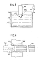
- This shape makes it possible to proceed in a simple, rapid and perfectly controlled manner to an electrodeposition of the material 42, as shown in FIG. 3.
- a solution 46 of the material that one wishes to deposit on the end of the rod 32 and to pass a current by means of a source 45 between the tank and the rod. It may especially be a nitric solution of the material to be ionized.
- the pointed end 32a of the rod is soaked to a perfectly controlled depth in solution 46 and electrolysis is carried out.
- a deposit 42 of the material to be ionized is thus obtained. In a known manner, this deposit will transform into oxide as soon as it is brought to a temperature of a few hundred degrees Celsius inside the tube 20.
- the material to be ionized can be fixed on a ball of ion exchange resin.
- the end of the rod 32 then has a different shape which is characterized by a recess, for example of conical shape, in which the resin ball is deposited on which the material to be ionized is fixed.
- the device according to the invention allows the deposition of the material to be ionized to be carried out without difficulty, which constitutes significant progress compared with known devices.
- the plate 22 is detachably fixed on a support 48, in order to allow the replacement of the tube 20-plate assembly 22 after manipulation, if necessary.
- This characteristic makes it possible in particular to avoid any risk of disturbance of a manipulation by the previous one.
- the support 48 also made of an electrically conductive material, is fixed to the part 38 by screws 52.
- the turn 26, the shield 30 and the terminals 28 are mounted in an insulating part 50 held by the part 48.
- the fixed part 38 made of stainless steel, has a part 38a which covers the insulating part 50.
- This part 38a is provided with a hole 54 in the extension of the straight end of the tube through which the ions exit. Part 38a thus constitutes the first electrode of the acceleration device 16 of FIG. 1.
- a sample of the material is first deposited on the end of the rod 32 by one of the methods described above and the rod is mounted on the screw 34. After having introduced this assembly as well as, if necessary, a tube 20 mounted on its plate 22, there is a vacuum in the enclosure.
- the opposite end of the tube 20 is heated by means of the electronic bombardment device 24.
- This heating is carried out initially weakly so that the degassing of the walls of the tube can be made, then at full power, the right end of the tube 20 considering Figure 2 then being brought as we have seen to a temperature of about 3000 ° C (the temperature limit being only fixed by the tube melting temperature).
- the tube 20 in fact constitutes a tubular oven, along which a temperature gradient is then established ranging from approximately 300 ° C. to approximately 3000 ° C.
- the end of the rod carrying the sample is continued to be moved towards the hot end of the tube, until the formation of ions is detected by means of the device. 18 ( Figure 1).
- the displacement of the rod being able to be perfectly controlled by the micrometric screw 34, or by any other equivalent means, it is possible to continue the progressive displacement of the sample until the ion current observed allows a suitable measurement to be made.
- the rod 32 is then held in this position and the measurements are carried out in the usual way.
- the device according to the invention it can be seen that the creation of a temperature gradient along the tube 20, combined with the controlled movement of the solid sample inside the tube, allows for perfectly controlled ionization of this sample.
- the rod 32 forms a piston which practically closes the end of the tube opposite the normal outlet end of the ions, and that the location of the heating means 24 in the immediate vicinity of this outlet end increases the probability that an ion re-evaporated by the surface of the tube leaves by this end.
- the intensity of the ion current and the ion yield are also improved.
- the device according to the invention has the essential advantage of being able to adapt without difficulty to the ionization of certain gas samples (for example uranium hexafluoride), which is not the case for the devices. ionization of solid materials known to date.
- certain gas samples for example uranium hexafluoride
- the conduit 56 then communicates with means for injecting the gas sample, by means of a throttle of adjustable section or any other equivalent device making it possible to control the flow rate of the gas injected into the tube.
- This constriction (not shown) plays a role comparable to the micrometric screw 34 in the embodiment of FIG. 2. Thus, to obtain an ion current reaching the desired intensity, the constriction is gradually opened so increasing the flow rate of the gas to be ionized.
Landscapes
- Physics & Mathematics (AREA)
- Engineering & Computer Science (AREA)
- Plasma & Fusion (AREA)
- Chemical & Material Sciences (AREA)
- Analytical Chemistry (AREA)
- Other Investigation Or Analysis Of Materials By Electrical Means (AREA)
- Electron Tubes For Measurement (AREA)
- Electron Sources, Ion Sources (AREA)
Applications Claiming Priority (2)
| Application Number | Priority Date | Filing Date | Title |
|---|---|---|---|
| FR8214774A FR2532470A1 (fr) | 1982-08-30 | 1982-08-30 | Dispositif d'ionisation d'un materiau par chauffage a haute temperature |
| FR8214774 | 1982-08-30 |
Publications (2)
| Publication Number | Publication Date |
|---|---|
| EP0104973A1 true EP0104973A1 (de) | 1984-04-04 |
| EP0104973B1 EP0104973B1 (de) | 1987-05-27 |
Family
ID=9277108
Family Applications (1)
| Application Number | Title | Priority Date | Filing Date |
|---|---|---|---|
| EP83401692A Expired EP0104973B1 (de) | 1982-08-30 | 1983-08-22 | Vorrichtung zur Ionisierung eines Materials durch Hochtemperaturheizung |
Country Status (5)
| Country | Link |
|---|---|
| US (1) | US4595835A (de) |
| EP (1) | EP0104973B1 (de) |
| JP (1) | JPS5963651A (de) |
| DE (1) | DE3371836D1 (de) |
| FR (1) | FR2532470A1 (de) |
Families Citing this family (7)
| Publication number | Priority date | Publication date | Assignee | Title |
|---|---|---|---|---|
| US4783595A (en) * | 1985-03-28 | 1988-11-08 | The Trustees Of The Stevens Institute Of Technology | Solid-state source of ions and atoms |
| US4833319A (en) * | 1987-02-27 | 1989-05-23 | Hughes Aircraft Company | Carrier gas cluster source for thermally conditioned clusters |
| DE3739253A1 (de) * | 1987-11-19 | 1989-06-01 | Max Planck Gesellschaft | Mit kontaktionisation arbeitende einrichtung zum erzeugen eines strahles beschleunigter ionen |
| FR2657723A1 (fr) * | 1990-01-26 | 1991-08-02 | Nermag Ste Nouvelle | Spectrometre de masse a filtre quadripolaire et tiroir mobile d'acces a la source ionique. |
| US5220167A (en) * | 1991-09-27 | 1993-06-15 | Carnegie Institution Of Washington | Multiple ion multiplier detector for use in a mass spectrometer |
| US6202870B1 (en) | 1999-03-29 | 2001-03-20 | Woodrow W. Pearce | Venting cap |
| US20080083874A1 (en) * | 2006-10-10 | 2008-04-10 | Prest Harry F | Vacuum interface for mass spectrometer |
Citations (2)
| Publication number | Priority date | Publication date | Assignee | Title |
|---|---|---|---|---|
| US3229157A (en) * | 1963-09-30 | 1966-01-11 | Charles M Stevens | Crucible surface ionization source |
| FR2045097A5 (en) * | 1969-05-30 | 1971-02-26 | Commissariat Energie Atomique | Lithium ion source |
Family Cites Families (3)
| Publication number | Priority date | Publication date | Assignee | Title |
|---|---|---|---|---|
| US2682611A (en) * | 1953-01-29 | 1954-06-29 | Atomic Energy Commission | Ion source |
| DE2548891C3 (de) * | 1975-10-31 | 1983-04-28 | Finnigan MAT GmbH, 2800 Bremen | Probenwechsler für Massenspektrometer |
| JPS583592B2 (ja) * | 1978-09-08 | 1983-01-21 | 日本分光工業株式会社 | 質量分析計への試料導入方法及び装置 |
-
1982
- 1982-08-30 FR FR8214774A patent/FR2532470A1/fr active Granted
-
1983
- 1983-08-19 US US06/524,828 patent/US4595835A/en not_active Expired - Fee Related
- 1983-08-22 EP EP83401692A patent/EP0104973B1/de not_active Expired
- 1983-08-22 DE DE8383401692T patent/DE3371836D1/de not_active Expired
- 1983-08-29 JP JP58157704A patent/JPS5963651A/ja active Pending
Patent Citations (2)
| Publication number | Priority date | Publication date | Assignee | Title |
|---|---|---|---|---|
| US3229157A (en) * | 1963-09-30 | 1966-01-11 | Charles M Stevens | Crucible surface ionization source |
| FR2045097A5 (en) * | 1969-05-30 | 1971-02-26 | Commissariat Energie Atomique | Lithium ion source |
Also Published As
| Publication number | Publication date |
|---|---|
| US4595835A (en) | 1986-06-17 |
| FR2532470A1 (fr) | 1984-03-02 |
| EP0104973B1 (de) | 1987-05-27 |
| JPS5963651A (ja) | 1984-04-11 |
| DE3371836D1 (en) | 1987-07-02 |
| FR2532470B1 (de) | 1985-05-17 |
Similar Documents
| Publication | Publication Date | Title |
|---|---|---|
| EP3344873B1 (de) | Gitter-ionenantrieb mit integriertem festtreibstoff | |
| US9536725B2 (en) | Means of introducing an analyte into liquid sampling atmospheric pressure glow discharge | |
| FR2537777A1 (fr) | Procede et dispositif d'implantation de particules dans un solide | |
| FR2705584A1 (fr) | Dispositif de séparation isotopique par résonance cyclotronique ionique. | |
| EP0104973B1 (de) | Vorrichtung zur Ionisierung eines Materials durch Hochtemperaturheizung | |
| FR2468203A1 (fr) | Appareil a decharge electrique a cathode creuse | |
| FR2588084A1 (fr) | Cuvette pour la spectroscopie par absorptions atomiques sans flamme | |
| FR2599556A1 (fr) | Procede de realisation d'un tube photomultiplicateur a element multiplicateur de proximite | |
| WO1995019565A1 (fr) | Dispositif d'injection automatique de produits solubilises ou dilues | |
| WO2009027596A2 (fr) | Source micronique d'émission ionique | |
| EP0142414B1 (de) | Ionenquelle insbesondere zum Erzeugen eines Stroms mehrfachgeladener metallischer Ionen, bei der der Ionenstrom geregelt wird | |
| EP0088649A1 (de) | Verfahren und Vorrichtung zur Adsorption von Wasserstoff mittels eines Adsorbermetalls und zur Freisetzung des adsorbierten Wasserstoffes | |
| FR2566174A1 (fr) | Dispositif pour l'emission d'electrons muni d'un corps emetteur d'electrons comportant une couche en un materiau reducteur du potentiel de sortie et procede permettant d'appliquer une telle couche en un materiau reducteur du potentiel de sortie | |
| EP4022107B1 (de) | Verfahren zum emittieren von atomen, molekülen oder ionen | |
| EP0446083B1 (de) | Temperaturmessungsverfahren und -vorrichtung für in einem thermo-chemischen Gefäss enthaltene Stücke | |
| EP0200645B1 (de) | Verfahren und Probeneinlassvorichtung für ein Massenspektrometer | |
| Dobson et al. | Electrical Conductance of Thin Ultrahigh‐Vacuum‐Evaporated Films of Tungsten on Glass | |
| FR2597286A1 (fr) | Dispositif et notamment duoplasmatron utilisable pour ioniser un gaz comprenant une cathode servant de cathode chaude ou froide et procede d'utilisation de ce dispositif | |
| EP0981657B1 (de) | Vorrichtung zur erstarrung und zur kontinuierlichen überwachung der kristallzüchtung | |
| US4340845A (en) | Stabilized cathode assembly for arc light source | |
| JP2557435B2 (ja) | 誘導結合プラズマ質量分析用試料導入装置 | |
| FR2623658A1 (fr) | Dispositif fonctionnant avec ionisation par contact pour l'elaboration d'un rayon d'ions acceleres | |
| JPS6177240A (ja) | 軟x線発生装置 | |
| CH420409A (fr) | Chalumeau à plasma et procédé pour sa mise en action | |
| FR2602443A1 (fr) | Procede et dispositif d'allumage d'un arc de coupage sur toles a revetement isolant |
Legal Events
| Date | Code | Title | Description |
|---|---|---|---|
| PUAI | Public reference made under article 153(3) epc to a published international application that has entered the european phase |
Free format text: ORIGINAL CODE: 0009012 |
|
| AK | Designated contracting states |
Designated state(s): BE DE GB |
|
| 17P | Request for examination filed |
Effective date: 19840908 |
|
| 17Q | First examination report despatched |
Effective date: 19860303 |
|
| GRAA | (expected) grant |
Free format text: ORIGINAL CODE: 0009210 |
|
| AK | Designated contracting states |
Kind code of ref document: B1 Designated state(s): BE DE GB |
|
| REF | Corresponds to: |
Ref document number: 3371836 Country of ref document: DE Date of ref document: 19870702 |
|
| BECN | Be: change of holder's name |
Effective date: 19870527 |
|
| RAP2 | Party data changed (patent owner data changed or rights of a patent transferred) |
Owner name: COMMISSARIAT A L'ENERGIE ATOMIQUE |
|
| PLBE | No opposition filed within time limit |
Free format text: ORIGINAL CODE: 0009261 |
|
| STAA | Information on the status of an ep patent application or granted ep patent |
Free format text: STATUS: NO OPPOSITION FILED WITHIN TIME LIMIT |
|
| 26N | No opposition filed | ||
| PGFP | Annual fee paid to national office [announced via postgrant information from national office to epo] |
Ref country code: DE Payment date: 19890727 Year of fee payment: 7 |
|
| PGFP | Annual fee paid to national office [announced via postgrant information from national office to epo] |
Ref country code: BE Payment date: 19890816 Year of fee payment: 7 |
|
| PGFP | Annual fee paid to national office [announced via postgrant information from national office to epo] |
Ref country code: GB Payment date: 19890831 Year of fee payment: 7 |
|
| PG25 | Lapsed in a contracting state [announced via postgrant information from national office to epo] |
Ref country code: GB Effective date: 19900822 |
|
| PG25 | Lapsed in a contracting state [announced via postgrant information from national office to epo] |
Ref country code: BE Effective date: 19900831 |
|
| BERE | Be: lapsed |
Owner name: COMMISSARIAT A L'ENERGIE ATOMIQUE Effective date: 19900831 |
|
| GBPC | Gb: european patent ceased through non-payment of renewal fee | ||
| PG25 | Lapsed in a contracting state [announced via postgrant information from national office to epo] |
Ref country code: DE Effective date: 19910501 |