EP0200645B1 - Verfahren und Probeneinlassvorichtung für ein Massenspektrometer - Google Patents
Verfahren und Probeneinlassvorichtung für ein Massenspektrometer Download PDFInfo
- Publication number
- EP0200645B1 EP0200645B1 EP19860400902 EP86400902A EP0200645B1 EP 0200645 B1 EP0200645 B1 EP 0200645B1 EP 19860400902 EP19860400902 EP 19860400902 EP 86400902 A EP86400902 A EP 86400902A EP 0200645 B1 EP0200645 B1 EP 0200645B1
- Authority
- EP
- European Patent Office
- Prior art keywords
- tube
- gaseous
- source
- heating
- microsample
- Prior art date
- Legal status (The legal status is an assumption and is not a legal conclusion. Google has not performed a legal analysis and makes no representation as to the accuracy of the status listed.)
- Expired
Links
- 238000000034 method Methods 0.000 title claims description 14
- 239000000523 sample Substances 0.000 claims description 30
- 239000007789 gas Substances 0.000 claims description 17
- 238000010438 heat treatment Methods 0.000 claims description 15
- 238000000859 sublimation Methods 0.000 claims description 9
- 150000001875 compounds Chemical class 0.000 claims description 8
- 230000008022 sublimation Effects 0.000 claims description 8
- IJGRMHOSHXDMSA-UHFFFAOYSA-N Atomic nitrogen Chemical compound N#N IJGRMHOSHXDMSA-UHFFFAOYSA-N 0.000 claims description 7
- 230000000694 effects Effects 0.000 claims description 5
- 239000007788 liquid Substances 0.000 claims description 5
- 239000012530 fluid Substances 0.000 claims description 4
- 229910052757 nitrogen Inorganic materials 0.000 claims description 4
- 230000001105 regulatory effect Effects 0.000 claims description 4
- 230000001276 controlling effect Effects 0.000 claims description 2
- 238000000151 deposition Methods 0.000 claims description 2
- 239000001307 helium Substances 0.000 claims description 2
- 229910052734 helium Inorganic materials 0.000 claims description 2
- SWQJXJOGLNCZEY-UHFFFAOYSA-N helium atom Chemical compound [He] SWQJXJOGLNCZEY-UHFFFAOYSA-N 0.000 claims description 2
- 239000000376 reactant Substances 0.000 claims 2
- 230000001131 transforming effect Effects 0.000 claims 2
- 150000002500 ions Chemical class 0.000 description 16
- 238000004458 analytical method Methods 0.000 description 10
- 230000000155 isotopic effect Effects 0.000 description 9
- 238000005259 measurement Methods 0.000 description 9
- 229910052770 Uranium Inorganic materials 0.000 description 3
- 238000010884 ion-beam technique Methods 0.000 description 3
- DNYWZCXLKNTFFI-UHFFFAOYSA-N uranium Chemical compound [U][U][U][U][U][U][U][U][U][U][U][U][U][U][U][U][U][U][U][U][U][U][U][U][U][U][U][U][U][U][U][U][U][U][U][U][U][U][U][U][U][U][U][U][U][U][U][U][U][U][U][U][U][U][U][U][U][U][U][U][U][U][U][U][U][U][U][U][U][U][U][U][U][U][U][U][U][U][U][U][U][U][U][U][U][U][U][U][U][U][U][U][U][U][U][U][U][U][U][U][U][U][U][U][U][U][U][U][U][U][U][U][U][U] DNYWZCXLKNTFFI-UHFFFAOYSA-N 0.000 description 3
- PXGOKWXKJXAPGV-UHFFFAOYSA-N Fluorine Chemical compound FF PXGOKWXKJXAPGV-UHFFFAOYSA-N 0.000 description 2
- PXHVJJICTQNCMI-UHFFFAOYSA-N Nickel Chemical compound [Ni] PXHVJJICTQNCMI-UHFFFAOYSA-N 0.000 description 2
- QVGXLLKOCUKJST-UHFFFAOYSA-N atomic oxygen Chemical compound [O] QVGXLLKOCUKJST-UHFFFAOYSA-N 0.000 description 2
- 238000006243 chemical reaction Methods 0.000 description 2
- 239000003153 chemical reaction reagent Substances 0.000 description 2
- 238000010586 diagram Methods 0.000 description 2
- 229910052731 fluorine Inorganic materials 0.000 description 2
- 239000011737 fluorine Substances 0.000 description 2
- 239000000203 mixture Substances 0.000 description 2
- 239000001301 oxygen Substances 0.000 description 2
- 229910052760 oxygen Inorganic materials 0.000 description 2
- 238000002360 preparation method Methods 0.000 description 2
- 238000005086 pumping Methods 0.000 description 2
- 239000000126 substance Substances 0.000 description 2
- 238000012546 transfer Methods 0.000 description 2
- SANRKQGLYCLAFE-UHFFFAOYSA-H uranium hexafluoride Chemical compound F[U](F)(F)(F)(F)F SANRKQGLYCLAFE-UHFFFAOYSA-H 0.000 description 2
- 229910002007 uranyl nitrate Inorganic materials 0.000 description 2
- OKTJSMMVPCPJKN-UHFFFAOYSA-N Carbon Chemical compound [C] OKTJSMMVPCPJKN-UHFFFAOYSA-N 0.000 description 1
- 229910000792 Monel Inorganic materials 0.000 description 1
- 229910052778 Plutonium Inorganic materials 0.000 description 1
- 239000012080 ambient air Substances 0.000 description 1
- 229910052799 carbon Inorganic materials 0.000 description 1
- 239000013626 chemical specie Substances 0.000 description 1
- 238000001816 cooling Methods 0.000 description 1
- 238000012937 correction Methods 0.000 description 1
- 239000013078 crystal Substances 0.000 description 1
- 230000007423 decrease Effects 0.000 description 1
- 238000007872 degassing Methods 0.000 description 1
- 230000008021 deposition Effects 0.000 description 1
- 238000013461 design Methods 0.000 description 1
- 230000005684 electric field Effects 0.000 description 1
- 238000005485 electric heating Methods 0.000 description 1
- 238000010894 electron beam technology Methods 0.000 description 1
- 238000001704 evaporation Methods 0.000 description 1
- 230000008020 evaporation Effects 0.000 description 1
- 238000000605 extraction Methods 0.000 description 1
- 239000012025 fluorinating agent Substances 0.000 description 1
- 238000003682 fluorination reaction Methods 0.000 description 1
- 238000005194 fractionation Methods 0.000 description 1
- 239000000446 fuel Substances 0.000 description 1
- 230000003993 interaction Effects 0.000 description 1
- 238000004949 mass spectrometry Methods 0.000 description 1
- 239000000463 material Substances 0.000 description 1
- 229910052751 metal Inorganic materials 0.000 description 1
- 239000002184 metal Substances 0.000 description 1
- 230000007935 neutral effect Effects 0.000 description 1
- 229910001120 nichrome Inorganic materials 0.000 description 1
- 229910052759 nickel Inorganic materials 0.000 description 1
- 150000002829 nitrogen Chemical class 0.000 description 1
- 239000002245 particle Substances 0.000 description 1
- 239000012071 phase Substances 0.000 description 1
- OYEHPCDNVJXUIW-UHFFFAOYSA-N plutonium atom Chemical compound [Pu] OYEHPCDNVJXUIW-UHFFFAOYSA-N 0.000 description 1
- 230000002285 radioactive effect Effects 0.000 description 1
- 239000003870 refractory metal Substances 0.000 description 1
- 238000000926 separation method Methods 0.000 description 1
- 239000007787 solid Substances 0.000 description 1
- 239000007790 solid phase Substances 0.000 description 1
- 238000007711 solidification Methods 0.000 description 1
- 230000008023 solidification Effects 0.000 description 1
- 230000006641 stabilisation Effects 0.000 description 1
- 238000011105 stabilization Methods 0.000 description 1
- 238000002076 thermal analysis method Methods 0.000 description 1
- 238000011144 upstream manufacturing Methods 0.000 description 1
- 239000003039 volatile agent Substances 0.000 description 1
- XLYOFNOQVPJJNP-UHFFFAOYSA-N water Chemical compound O XLYOFNOQVPJJNP-UHFFFAOYSA-N 0.000 description 1
- 238000003466 welding Methods 0.000 description 1
- 238000004804 winding Methods 0.000 description 1
Images

Classifications
-
- H—ELECTRICITY
- H01—ELECTRIC ELEMENTS
- H01J—ELECTRIC DISCHARGE TUBES OR DISCHARGE LAMPS
- H01J49/00—Particle spectrometers or separator tubes
- H01J49/02—Details
- H01J49/04—Arrangements for introducing or extracting samples to be analysed, e.g. vacuum locks; Arrangements for external adjustment of electron- or ion-optical components
- H01J49/0422—Arrangements for introducing or extracting samples to be analysed, e.g. vacuum locks; Arrangements for external adjustment of electron- or ion-optical components for gaseous samples
-
- H—ELECTRICITY
- H01—ELECTRIC ELEMENTS
- H01J—ELECTRIC DISCHARGE TUBES OR DISCHARGE LAMPS
- H01J49/00—Particle spectrometers or separator tubes
- H01J49/02—Details
- H01J49/04—Arrangements for introducing or extracting samples to be analysed, e.g. vacuum locks; Arrangements for external adjustment of electron- or ion-optical components
- H01J49/0468—Arrangements for introducing or extracting samples to be analysed, e.g. vacuum locks; Arrangements for external adjustment of electron- or ion-optical components with means for heating or cooling the sample
-
- H—ELECTRICITY
- H01—ELECTRIC ELEMENTS
- H01J—ELECTRIC DISCHARGE TUBES OR DISCHARGE LAMPS
- H01J49/00—Particle spectrometers or separator tubes
- H01J49/02—Details
- H01J49/04—Arrangements for introducing or extracting samples to be analysed, e.g. vacuum locks; Arrangements for external adjustment of electron- or ion-optical components
- H01J49/0495—Vacuum locks; Valves
Definitions
- the invention relates to the field of analysis of samples by mass spectrometry and it relates more particularly to the methods and devices making it possible to introduce, into the spectrometer, a sample microdebit whose ions are subjected to analysis.
- mass spectrometers use either a source of thermionic ions or a source of ions with electron bombardment of a gas flow.
- the first solution has the advantage of making it possible to use samples of very low mass, frequently between 0.1 and 10 micrograms.
- the sample is deposited, usually in liquid form, on a refractory metal tape. By evaporation of the liquid, a solid deposit is obtained.
- the ribbon is placed in the ion source of the device, then brought to high temperature (2600 ° C for example) by Joule effect.
- the sample then emits neutral molecules and ions. The latter, accelerated and focused in the form of a particle beam, are subjected to analysis.
- a mass spectrometer using a thermionic source cannot be used to conduct chemical composition analyzes and can very easily be connected online to a separation or treatment line.
- the usual method consists in introducing the sample from a sealed container through piping and micro-leakage valves allowing a well determined and very low gas flow to pass without altering the very low pressure which must prevail in the analyzer of the spectrometer.
- the molecules of gas or vapor which pass at very low flow rate are subjected to the action of a beam of electrons of determined energy which ionizes the gas to give rise to ions subjected to analysis.
- the intensity of ion currents obtained is usually of the order of 10 -9 A, that is to say, much higher than the thermal-spectrometer, which simplifies the measurement.
- measurements made using a spectrometer using an ion source by electron bombardment are generally differential measurements, which guarantee high precision, typically 50 to 100 times higher than with a thermionization source.
- document US-A-3 888 107 describes a thermal analysis cell using a reactive gas, the necessity of which stems from the requirements of the analysis method used.
- the present invention aims to provide a supply method and device for a mass spectrometer, using the ionization technique of a very low flow rate, typically using an electron beam, but responding better than those previously known to the requirements of the practice, in particular in that they authorize the use of samples of very low mass.
- the invention provides a method of introducing micro-samples in accordance with the characterizing part of claim 1 and a device making it possible to implement this method, in accordance with the characterizing part of claim 2.
- this device keeps the device all the advantages of using an electron bombardment source it allows to work with relatively intense ion beams, which simplifies their measurement it avoids breaking the vacuum in the source to introduce the sample it is not necessary to have watertight containers to handle the samples and connect them to the device.
- the proposed device has many advantages: the size of the samples to be analyzed is reduced to a few micrograms; It is not necessary to have sealed containers for handling the samples and introducing them into the device. The consumption of standards or reference products can be reduced to the order of magnitude of that of the samples, the preparation of which is simple and fast.
- the device shown in Figures 1 and 2 can be viewed as comprising a reactor 10, the essential element of which is a micro-oven with adjustable temperature, a passage 12 sufficiently constricted for the flow to take place therein in the form of molecular flow, and a micro- sublimers 14.
- the microsublimeter is connected, by means of a valve 16, to the ion source 18 of the spectrometer, which can be of any of the types making it possible to ionize a low flow of gas which penetrates him. Typically, this source will perform ionization by electron bombardment.
- the reactor 10 the schematic diagram of which is shown in FIG. 1, comprises an enclosure, generally cylindrical, in the axis of which is placed the actual micro-oven 20 consisting of a metal tube capable of withstanding high temperatures, for example nickel , nichrome or "monel". Means are provided for heating the oven by the Joule effect.
- these means are shown in the form of an electrical source 22 connected to one end of the tube of which the other is grounded.
- Another solution consists in winding an electric heating resistor around the tube 20.
- This tube can carry a temperature sensor 24 connected to a circuit 26 for regulating the temperature by modulating the electric power supplied by the source 22.
- a sample holder 28 is provided to allow the introduction of a very small quantity of samples, in the form of a deposit on a needle or a thread.
- the head of this sample holder will be provided to seal the microfour.
- One end of the tube 20 forming a micro oven is connected, by a valve 30, to a vacuum source 32 (mechanical primary pump for example) and to a source 34 of reagent. of a nature such that it gives rise, with the sample, to a gaseous or volatile compound.
- the sources 32 and 34 are each provided with a shut-off valve 36 and 38.
- the valves 30 and 38 at least must be made of a material resistant to very corrosive gases, since it will frequently be necessary to use highly reactive chemical species, such as fluorine.
- the valve 30 must also be strictly sealed.
- the constricted passage 12 may have a fixed passage section.
- a diaphragm or capillary conduit can also be adjustable and formed by a conventional type micro-leakage valve or a piezoelectric valve, the opening of which is caused by the deformation of a piezoelectric crystal under the action of an electric field.
- the passage must prohibit any entry of ambient air and it must offer a passage section having a sufficiently small diameter (typically a few microns) so that the gas flow between the reactor 10 and the microsublimation tube maintained at low pressure or in molecular regime. We know that in this regime the free path of the gaseous molecules is greater than the transverse dimensions of the passage.
- the microsublimator 14 will generally consist of a tube 40 of small diameter, one end of which is tightly connected to the passage 12 and the other end is connected, by means of the valve 16, to the ion source 18.
- This tube is provided with cryogenic temperature cooling means.
- cryogenic temperature cooling means These means are shown in Figure 1 in the form of an enclosure 42 provided with an inlet and an outlet for fluid at very low temperature.
- adjustable heating means are associated with it. In the case of FIG. 1, these means consist of a heating resistor 44 wound around the tube 40 and supplied by an electric generator 46 of adjustable power.
- a temperature probe can be placed on the tube 40 to regulate, via a circuit similar to circuit 26, the temperature of the tube to an adjustable value. This temperature can also be slaved to a reference value by the intensity of the ion beams received at the collectors of the mass spectrometer.
- a signal is taken from the ion current amplifier. This is constantly compared with a reference representing the chosen temperature, this reference being able to be programmed itself using a computer. A voltage is therefore obtained which is converted into calibrated pulses giving quantities of energy supplying the heating systems of the tube 40.
- a valve 46a in parallel with the valve 16, makes it possible to connect the outlet of the tube 40 to a vacuum pump.
- An additional connector provided with a valve 47 may be provided to connect the ion source to a reference gas supply and / or to another device similar to that which has just been described.
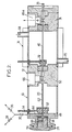
- the elements 10, 12 and 14 of FIG. 1 are grouped together to constitute a one-piece assembly in several assembled parts, for example by welding.
- the reactor is delimited by two nozzles 48 and 50 and a cylindrical shell in the axis of which the tube 20 is placed, a few millimeters in internal diameter, forming the micro-oven.
- the downstream end of this tube is grounded via the end piece 50.
- the upstream end isolated from ground by a pin 52, is connected to the electrical heating source by means of a tab 54 which crosses the shell in a sealed manner.
- the sample holder 28 comprises a head screwable into the end piece 48, the seal being ensured by a seal 58.
- a locking screw 60 provided in the head makes it possible to retain a thread or a needle 62 for supporting the dry sample.
- a channel 64 formed in the end piece 48 makes it possible to connect the tube 20 to a valve 30 for admitting the reagent (gaseous fluorinating agent in general) or to a vacuum pump.
- a seat 66 intended to receive the micro-leakage valve (not shown) constituting the passage 12 towards the micro-sublimator 14.
- the latter has a constitution very comparable to that of the reactor 10, if this n 'is that the ferrule is provided with inlet and outlet fittings 68 and 70 for cryogenic fluid.
- the micro-sublimation tube 40 is connected, via an insulating pin 72, to the end piece 50 and its downstream end is welded to an end piece 74 provided with a seat intended for the valve 46a (not shown) .
- this nozzle comprises a tubular extension 76 intended to be connected to the valve 16.
- the device used is of the type shown in FIG. 2.
- the sample must first be transferred to the sample holder 28.
- the wire 62 which for example is 0.8 mm in diameter and 7 cm long, is deposited, using a micro-pipette , a few drops of uranyl nitrate containing a total of for example 10 micrograms of uranium to be analyzed.
- Uranyl nitrate transforms into a deposit of U0 3 , then U 3 0 8 when the temperature exceeds 350 ° C.
- the wire covered with the deposit is placed in the sample holder 28 and the latter fixed on the end piece 48.
- the tube 20 is put under vacuum by pumping up to a pressure of the order of 0.133 Pa (10- 3 torr). Then we heat the tube 20, by current flow. up to a temperature of around 400 ° C to remove residual water vapor.
- the temperature of the microsublimation tube 40 is then brought to that of the liquid nitrogen by circulation of this nitrogen around the tube 40, from the connector 68 to the connector 70 by the circulation of a heat transfer gas (helium for example) brought to the temperature. liquid nitrogen.
- a heat transfer gas helium for example
- valve 12 is closed.
- the pumping valve 46a is open, and the tube 40 is very gradually heated by passing an electric current. The oxygen sublimes and it is evacuated by the vacuum pump, through the valve 46a.
- the valve 46 is closed and the valve 16 is opened.
- the heating is carried out with a temperature programming such that, as soon as the hexafluoride flow rate reaches a predetermined value (that is to say when the value is reached of the intensity of the ion beam in the spectrometer), the temperature is controlled, so that the flow rate, measured by means not shown, remains constant until the mass of trapped uranium hexafluoride is used up
- a predetermined value that is to say when the value is reached of the intensity of the ion beam in the spectrometer
- Another solution consists in using two devices of the kind shown in FIG. 2. One of them receives a wire carrying a deposit whose isotopic ratio is to be measured, the other a deposit of U 3 0 8 of known isotopic composition .
- the invention is not however limited to these particular embodiments. It is applicable whenever a reaction giving a gaseous compound of the sample is available.
- the method is applicable to the case of carbon, which can be fluorinated to give CF 4 , which is particularly interesting for the isotopic analysis C 12 / C l4 used in dating.
Landscapes
- Chemical & Material Sciences (AREA)
- Analytical Chemistry (AREA)
- Other Investigation Or Analysis Of Materials By Electrical Means (AREA)
Claims (8)
Applications Claiming Priority (2)
| Application Number | Priority Date | Filing Date | Title |
|---|---|---|---|
| FR8506257 | 1985-04-24 | ||
| FR8506257A FR2581246B1 (fr) | 1985-04-24 | 1985-04-24 | Procede et dispositif d'introduction d'echantillons pour spectrometre de masse |
Publications (2)
| Publication Number | Publication Date |
|---|---|
| EP0200645A1 EP0200645A1 (de) | 1986-11-05 |
| EP0200645B1 true EP0200645B1 (de) | 1989-07-12 |
Family
ID=9318634
Family Applications (1)
| Application Number | Title | Priority Date | Filing Date |
|---|---|---|---|
| EP19860400902 Expired EP0200645B1 (de) | 1985-04-24 | 1986-04-24 | Verfahren und Probeneinlassvorichtung für ein Massenspektrometer |
Country Status (5)
| Country | Link |
|---|---|
| EP (1) | EP0200645B1 (de) |
| CA (1) | CA1263765A (de) |
| DE (1) | DE3664401D1 (de) |
| FR (1) | FR2581246B1 (de) |
| WO (1) | WO1986006545A1 (de) |
Families Citing this family (1)
| Publication number | Priority date | Publication date | Assignee | Title |
|---|---|---|---|---|
| FR2629270B2 (fr) * | 1988-03-25 | 1990-12-28 | Cogema | Dispositif d'introduction d'echantillons pour spectrometre de masse |
Family Cites Families (3)
| Publication number | Priority date | Publication date | Assignee | Title |
|---|---|---|---|---|
| FR1132049A (fr) * | 1954-05-26 | 1957-03-04 | Thomson Houston Comp Francaise | Dispositif d'introduction d'un échantillon dans un spectrographe de masse |
| US3888107A (en) * | 1969-10-08 | 1975-06-10 | Dow Chemical Co | Differential thermal analysis cell assembly |
| DE3269499D1 (en) * | 1981-11-30 | 1986-04-03 | Vg Instr Group | Automatic mass spectrometer inlet system |
-
1985
- 1985-04-24 FR FR8506257A patent/FR2581246B1/fr not_active Expired
-
1986
- 1986-04-24 CA CA000507538A patent/CA1263765A/fr not_active Expired
- 1986-04-24 EP EP19860400902 patent/EP0200645B1/de not_active Expired
- 1986-04-24 WO PCT/FR1986/000140 patent/WO1986006545A1/fr not_active Ceased
- 1986-04-24 DE DE8686400902T patent/DE3664401D1/de not_active Expired
Also Published As
| Publication number | Publication date |
|---|---|
| DE3664401D1 (en) | 1989-08-17 |
| FR2581246A1 (fr) | 1986-10-31 |
| FR2581246B1 (fr) | 1987-07-10 |
| WO1986006545A1 (fr) | 1986-11-06 |
| EP0200645A1 (de) | 1986-11-05 |
| CA1263765A (fr) | 1989-12-05 |
Similar Documents
| Publication | Publication Date | Title |
|---|---|---|
| Chan et al. | Study of laser-material interactions using inductively coupled plasma-atomic emission spectrometry | |
| US4902891A (en) | Thermospray methods and apparatus for interfacing chromatography and mass spectrometry | |
| EP2195643B1 (de) | System zur analyse eines niederdruckgases mittels optischer emissionsspektroskopie | |
| EP0016909A1 (de) | Verfahren zur Plasma-Oxidierung von Halbleitersubstraten und Vorrichtung zur Durchführung dieses Verfahrens | |
| Dunning et al. | Atomic, molecular, and optical physics: Atoms and molecules | |
| EP0200645B1 (de) | Verfahren und Probeneinlassvorichtung für ein Massenspektrometer | |
| FR2637725A1 (fr) | Dispositif d'extraction et d'acceleration des ions limitant la reacceleration des electrons secondaires dans un tube neutronique scelle a haut flux | |
| US4933548A (en) | Method and device for introducing samples for a mass spectrometer | |
| Mancini et al. | Synchrotron radiation induced chemical vapor deposition of thin films from metal hexacarbonyls | |
| EP1212779A2 (de) | Nachweis- und analysevorrichtung durch laserabtragung und übertragung in eine spektrometerionenfalle sowie zugehöriges verfahren | |
| FR2532470A1 (fr) | Dispositif d'ionisation d'un materiau par chauffage a haute temperature | |
| EP0783192B1 (de) | Metalldampflaservorrichtung | |
| Imai et al. | Investigations of pyrolysed ascorbic acid in an electrothermal graphite furnace by inductively coupled argon plasma mass spectrometry and Raman spectrometry | |
| GB2240176A (en) | Introduction of affluent into mass spectrometers and other gas-phase or particle detectors | |
| FR3022027A1 (fr) | Dispositif et procede d'analyse d'un echantillon solide par spectrometrie de decharge luminescente | |
| FR2629270A2 (fr) | Dispositif d'introduction d'echantillons pour spectrometre de masse | |
| JP2557473B2 (ja) | 誘導結合プラズマ質量分析用試料導入装置 | |
| JP2557435B2 (ja) | 誘導結合プラズマ質量分析用試料導入装置 | |
| FR2597286A1 (fr) | Dispositif et notamment duoplasmatron utilisable pour ioniser un gaz comprenant une cathode servant de cathode chaude ou froide et procede d'utilisation de ce dispositif | |
| JP2598073B2 (ja) | 誘導結合プラズマ質量分析用試料導入装置 | |
| FR2684497A1 (fr) | Laser impulsionnel. | |
| Reid et al. | The relation between current flow and oxygen adsorption in a reverse biassed silicon pn junction | |
| Goodfellow et al. | Experimental verification of a high-current cathode thermal model | |
| FR2773300A1 (fr) | Torche a plasma et installation d'analyse de gaz utilisant une telle torche | |
| GB2633186A (en) | Apparatus for inductively coupled plasma mass spectrometry |
Legal Events
| Date | Code | Title | Description |
|---|---|---|---|
| PUAI | Public reference made under article 153(3) epc to a published international application that has entered the european phase |
Free format text: ORIGINAL CODE: 0009012 |
|
| AK | Designated contracting states |
Kind code of ref document: A1 Designated state(s): DE GB |
|
| 17P | Request for examination filed |
Effective date: 19870110 |
|
| 17Q | First examination report despatched |
Effective date: 19880324 |
|
| GRAA | (expected) grant |
Free format text: ORIGINAL CODE: 0009210 |
|
| AK | Designated contracting states |
Kind code of ref document: B1 Designated state(s): DE GB |
|
| REF | Corresponds to: |
Ref document number: 3664401 Country of ref document: DE Date of ref document: 19890817 |
|
| GBT | Gb: translation of ep patent filed (gb section 77(6)(a)/1977) | ||
| PLBE | No opposition filed within time limit |
Free format text: ORIGINAL CODE: 0009261 |
|
| STAA | Information on the status of an ep patent application or granted ep patent |
Free format text: STATUS: NO OPPOSITION FILED WITHIN TIME LIMIT |
|
| 26N | No opposition filed | ||
| PGFP | Annual fee paid to national office [announced via postgrant information from national office to epo] |
Ref country code: GB Payment date: 19920416 Year of fee payment: 7 |
|
| PGFP | Annual fee paid to national office [announced via postgrant information from national office to epo] |
Ref country code: DE Payment date: 19920418 Year of fee payment: 7 |
|
| PG25 | Lapsed in a contracting state [announced via postgrant information from national office to epo] |
Ref country code: GB Effective date: 19930424 |
|
| GBPC | Gb: european patent ceased through non-payment of renewal fee |
Effective date: 19930424 |
|
| PG25 | Lapsed in a contracting state [announced via postgrant information from national office to epo] |
Ref country code: DE Effective date: 19940101 |