EP0105619A2 - Système de réduction de bruit à mesure multiple - Google Patents
Système de réduction de bruit à mesure multiple Download PDFInfo
- Publication number
- EP0105619A2 EP0105619A2 EP83305111A EP83305111A EP0105619A2 EP 0105619 A2 EP0105619 A2 EP 0105619A2 EP 83305111 A EP83305111 A EP 83305111A EP 83305111 A EP83305111 A EP 83305111A EP 0105619 A2 EP0105619 A2 EP 0105619A2
- Authority
- EP
- European Patent Office
- Prior art keywords
- processed image
- signal
- filtered
- noise
- measurements
- Prior art date
- Legal status (The legal status is an assumption and is not a legal conclusion. Google has not performed a legal analysis and makes no representation as to the accuracy of the status listed.)
- Granted
Links
Images



Classifications
-
- H—ELECTRICITY
- H04—ELECTRIC COMMUNICATION TECHNIQUE
- H04N—PICTORIAL COMMUNICATION, e.g. TELEVISION
- H04N23/00—Cameras or camera modules comprising electronic image sensors; Control thereof
- H04N23/30—Cameras or camera modules comprising electronic image sensors; Control thereof for generating image signals from X-rays
Definitions
- This invention relates to x-ray imaging systems.
- the invention relates to the processing of images derived from a plurality of x-ray measurements.
- images are constructed as a weighted sum of a plurality of measurements.
- a prime example are the recent new developments in x-ray imaging. Here measurements are made at different energies and/or at different times. These measurements are then combined to provide selective images representing specific materials.
- a third example is energy-selective computerized tomography as described in the publication by R.E. Alvarez and A. Macovski, "Energy-Selective Reconstructions in X-ray Computerized Tomography.” in Physics in Medicine & Bioiogy, Vol. 21, pp. 733-744, 1976.
- sets of measurements are made at two energy spectra and distortion-free reconstructions are made which delineate the average atomic number and density of each region.
- a fourth example is hybrid subtraction described in U.S. Application 6-260694. filed 5/5/81 and in the publication by W.R. Brody. "Hybrid Subtraction for Improved Intravenous Arteriography," in Radiology, Vol. 141, pp. 828-831, 1981.
- dual energy measurements are made before and after the administration of iodine. Each dual energy pair is used to eliminate soft tissue. In this way the resultant subtracted vessel images are immune to soft tissue motion.
- the techniques employed in the present invention are generally related to those employed in color television systems for bandwidth reduction- In color television the high frequency components for all three color channels are derived from the luminance signal.
- Systems for adding the correct amount of high frequency component to each color channel are described in U.S. Patent 2,833,851 issued to Loughlin and U.S. Patent 4,181,917 issued to Richman. These patents do not, however, address the problem of excessive noise in a selective image derived from a plurality of measurements, such as occurs in many x-ray imaging systems.
- An object of this invention is to provide a system for improving the signal-to-noise ratio in images derived from a plurality of measurements.
- a further object of the invention is to improve the signal-to-noise ratio of material-selective x-ray images.
- Another object of the invention is to improve the signal-to-noise ratio in blood vessel images where measurements are taken with and without the presence of a contrast agent.
- Yet another object of the invention is to improve the signal-to-noise ratio of computerized tomography images derived from two or more measurements.
- an array of measurements are taken of an object under different conditions. These are combined to select a specific aspect of the object. The same measurements are then combined in different weightings to provide a lower-noise image, without the desired selectivity.
- the improved selective image is formed by combining the selective image with the lower noise image using the lower frequency components of the former and the higher frequency components of the latter. To assure the proper amplitude of the higher frequency components, the components are weighted with the ratio of the derivative of the selective irnage to the derivative of the lower noise image. Nonlinear thresholds are used for those cases where this ratio becomes an unreliable indicator of the correct amplitude of the high frequency components.
- Figure 1 is a block diagram of an x-ray system useful in one embodiment of the invention.
- X-ray source 8 is an x-ray tube supplied by variable voltage power source 3.
- the x-rays are transmitted through object 1, normally the human anatomy.
- the transmitted rays are received by x-ray detector 4, such as an image intensifier and television camera, or a one or two-dimensional array of scintillators, etc.
- the image signal 5 is applied to image storage system 6 where a plurality of images 9, 10, 11, 12,. etc., can be stored.
- a first image 9 is stored.
- a second image 10 is stored. These are then used in the subsequent processing systems.
- images 9, 10, 11, 12, etc. are stored at different values of beam energy corresponding
- the lines 9, 10, 11 and 12 representing an array of x-ray measurements of an object, are processed in accordance with the invention.
- These signals could be obtained, for example, from the output of the television camera in a fluoroscopic system where an array of images are formed and stored, for example, on a magnetic disc or in a solid-state frame memory.
- These signals can represent x-ray images taken with different photon energy spectra or taken before and after the administration of a contrast agent.
- the multiple measurements are taken so as to provide the isolation or elimination of specific materials.
- One simple example involves the isolation of vessel images by subtracting measurements taken before and after the administration of an iodinated contrast agent:
- Other examples include measurements at different x-ray photon energy spectra which are then combined to eliminate or enhance specific materials.
- Weighted summer 13 takes the measurements and provides selective signal 17, containing the desired material properties. Unfortunately, however, signal 17 often has relatively poor SNR. The weighted sum usually involves negative weights which diminish the signal. The noise variances of each independent measurement add, however, to provide a large variance, hence a low SNR. This SNR is considerably improved using low pass filler 15 which reduces the bandwidth. This noise reduction, however, is accomplished at the price of reduced resolution. A primary objective of this invention to restore the resolution using a source of high-frequency information with reduced noise.
- Weighted summing structure 14 Signals 9, 10, 11 and 12 are also applied to weighted summing structure 14. i These weights are chosen to maximize the signal-to-noise ratio for a particular component of the image. For example, for vessel imaging they are chosen to maximize the signal-to-noise ratio for the iodinated contrast agent. This is in sharp distinction to weighted summing structure 13 where the weights are chosen to isolate iodine and eliminate the various tissue components. Ideally the weights which maximize the SNR will vary in different portions of the image, depending on the intervening tissue. Thus the weights can be vatied as the signals are scanned. However, for simplicity, the weights can be fixed to maximize the average SNR with relatively small degradation in performance.
- the low SNR weighted-sum signal. 18, is applied to high pass filter 16 which extracts the high frequency components.
- a preferred embodiment of this high pass filter is the complement of low pass filter 15.
- the sum of the normalized transmissions equals unity within the frequencies of interest.
- Combiner 21 combines the low frequency image or signal 19 with the high ; frequency image or signal 20 to obtain the processed image 22 which is displayed in display 23. Since signal 19 is low noise because of the filtering and signal 20 is low noise because of the weightings, the processed signal 22 is a low noise version of the desired signal, having the full bandwidth or resolution.
- the degree of artifacts in the image can depend on the nature of the combiner 21.
- the combiner 21 can simply be an adder.
- the desired selected image will have the required low noise and high resolution.
- signal 20 contains the high frequency components of undesired structures.
- signal 20 contains the edges of undesired structures such as bone and various soft tissue organs. Since these are only edges, however, a trained radiologist can ignore them and concentrate on the vessels.
- summer 13 weights the four signals to eliminate everything but iodine, while also subtracting soft tissue motion artifacts.
- Summer 14 can, for example, weight the signals to provide a low noise temporal subtraction, without concern about soft tissue motion artifacts. This can be accomplished by using a large positive weight for the low energy signal before iodine is administered, and a smaller positive weight for the high energy signal since it contains less of the iodine component. These weights are reversed for the measurements taken after the iodine administration to provide a temporal subtraction of everything except iodine.
- signal 17 is given by where A represents the different measurements and the canstants a; are chosen to select or eliminate a specific material. 'These same A measurements are again combined to form where the b i factors are chosen to provide an improved SNR. even if undesired components are present. As indicated, it may be desirable to vary the b i values at different portions of the image to optimize the SNR.
- this approach will have artifacts representing edges from M h of undesired components.
- the SNR of M is compromised to minimize these artifacts.
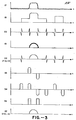
- Signal 17 illustrates the desired isolated vessel image or S signal. Unfortunately, as shown, this signal has a poor SNR.
- Signal 18 is the M signal containing a good SNR with undesired components.
- S is obtained by adding signal 20 to signal 19, the low frequency version of S, S i . The desired S signal will be restored to its full resolution and the noise will be greatly reduced. However, undesired edge components will exist at the transitions of the undesired components of signal 1B.
- the amount of high frequency information added M h is controlled by the transitions of S i
- transitions in other regions of M will not cause undesired artifacts.
- M h we weight M h by the ratio of the amplitude of the transitions of S, ⁇ i . to those of M. ⁇ i .
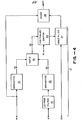
- S j . signal 19 take its derivative in 31, to form ⁇ i . signal 33.
- the derivative operation can be taken using classic analog operations or be performed as a digital differencing operation. Also, the derivative can be approximated by a high pass or bandpass filter.
- Signal ⁇ i . the derivative of the low frequency components of M . is formed by filtering the M signal 1B with low pass filter 30. This can be identical to filler 15 in Figure 2. Its derivative is taken in differentiator 32 to form ⁇ i . signal 34. The ratio of the derivatives is taken in ratio structure 35. This can be accomplished using a digital divider, or by taking the difference of the logs and then taking the exponent or anti-log. The ratio, signal 36, ignoring controlled switch 50, controls the gain of multiplier 37 which varies the amplitude of the added M h .
- the ratio of ⁇ i 33, to ⁇ i 34 is shown as signal 36.
- This signal selects only the proper amplitude of the transition signals 20 corresponding to S.
- the product of signal 36 and signal 20 is added to signal 19 in adder 3B to provide the desired S signal with low noise and high resolution.
- This signal is relatively devoid of artifacts since transitions outside of S will not be amplified by ratio signal 36.
- the same low pass filter 15 is used for Si and ⁇ i . the derivative signal used to control M h . In general, however, these need not represent the same filter operations. In some cases narrower bandwidth low pass filtering might be used for the differentiated signals considering the noise sensitivity of a ratio operation. In that case additional low pass filtering can be applied between signal 19 and differentiator 31 or between original S signal 17 and differentiator 31. Correspondingly filter 30 can be made narrower band than that of filter 15.
- threshold structures 51, 52 and 53 can be used to provide signal 54 to activate the controlled switch 50.
- Threshold structure 52 measures S i , signal 33, to ascertain if it falls below some predetermined level, such as its r.m.s. noise level. If it does, it is assumed that S has no transitions in that region, and switch 50 is disabled. Similarly if M i . signal 34 falls below some relatively low level set in threshold structure 53, it is again assumed that S has no transitions of interest and switch 50 is disabled. In addition if the ratio signal 36 exceeds some absolute level beyond its normal range, the controlled switch is again disabled. Either one of these three prevents most artifacts, and the combination should take care of all contingencies. Care should be taken in the setting of the thresholds to avoid missing desired transitions.
- threshold structures 5 1 , 52 and 53 must ascertain whetber the magnitude of the respective signals exceeds a given level. This can accomplished by having the threshold structures include an absolute value system, such as a phase splitter followed by a full wave reciifier. Alternatively, the threshold structures themselves can include the appropriate positive and negative threshold settings, thus taking both polarities into account.
- multiplier 37 when the threshold was exceeded, multiplier 37 was disabled, providing zero gain. such that the processed signal 22, S , became simple equal to S i .
- one potential difficulty with this approach is the loss of high frequency response for very low amplitude signals.
- very small vessels might be obliterated since the thresbold devices turned off the high-frequency components.
- One solution to this problem using the same structure as Figure 4 is to have controlled switch 50 disable ratio signal 36 and then provide multiplier 37 with a fixed gain, rather than zero gain. This gain could be fixed to provide a signal given by providing the correct high frequency amplitude. In this way small structures, such as vessels, would not be obliterated.
- Figure 6 illustrates an alternate combiner 21 which does not involve a ratio operation and is therefore a more stable system. It is particularly of interest in vessel imaging systems. It is, essentially, an improvement over the simplest combiner where the signals are merely added. In essence, where S l and M h are added, transitions occur outside of the region of interest.
- the embodiment of Figure 4- uses gating of controlled switch 50 to allow transitions solely in the regions of interest, namely. the edges of S .
- signal 19 in Figure 6 is applied directly to limiter 42. This provides a square gating signal wherever signal 19, S i , is non- zero. As can be seen in Figure 3, only the desired transitions of signal 20, M h . will be gated in by switching on controlled switch 43. The undesired transitions will not appear since they do not coincide with the limited S i signal.
- Amplifier 44 provides the correct gain for M h to be added to A i . If the constants b; vary for different portions of the image. then amplifier 44 is made a variable gain amplifier whose gain varies with the choice of constants b; used to produce the M. low-noise, signal.
- signal 45 the limited absolute value of S i . can also be used to stabilize the embodiment of Figure 4.
- Signal 45 is used to provide signal 54 to control controlled switch 50 which applies the ratio signal 36 to multiplier 37. In this way, M h components outside of the desired transitions will not be passed by controlled amplifier 37 since it will be turned off by switch 50.
- multiplier 60 the two derivative signals previously described S i and M i are multiplied in multiplier 60. If these are of the same polarity, the output will be positive, while if these are of opposite polarity the output will be negative going pulses. These pulses are applied to bipolar limiter 61.
- This limiter provides the mathematical sign function (e.g., +1 or -1) providing either a fixed positive or negative output depending on whether the input is positive or negative.
- a small threshold region can be incorporated to provide zero output when product signal 64 is below a given level. This will avoid triggering by noise.
- the bipolar clipped signal is used to determine the polarity of the M h signal.
- the M h signal is first appropriately amplified by amplifier 44 and then phase split by phase splitter 62 to provide positive and negative versions.
- the correct polarity is selected by polarity-selecting switch 63 in accordance with the polarity of signal 65, the output of the bipolar limiter. This corrected M h signal is added to S, in 3B to provide S , signal 22.
- each of the foregoing embodiments can be used as one-dimensional or two-dimensional systems.
- the various signals used can represent the classical raster scan of a two-dimensional image where time represents the horizontal or x dimension.
- each of the filtering and derivative operations would be performed on the scanned signal, representing one-dimensional filtering in the horizontal or x dimension.
- one-dimensional filtering will provide the desired noise reduction, the reduction is more effective if done in both dimensions.
- One approach to two-dimensional filtering is simply to reverse the scanning sequence and repeat the one-dimensional process in the other dimension. That is, once a reduced S is produced using the various filtering and derivative processes in the horizontal or x direction, the entire process is repeated in the vertical or y dimension starting with the processed S signal. In this way, further noise reduction will be achieved.
- the low pass and high pass filter operations can be two-dimensional filters, with the derivative operations represented by the sum of partial derivatives in each dimension as given by
- the operations can be performed in the space or frequency domains.
- the operations in space represent one or two-dimensional convolutions while in the frequency domain they would represent one or two-dimensional filters on the frequency spectra of the S or M signals.
- the final estimated image S have the proper composite of low and high frequency information to create a high fidelity representation of the original S image.
- the low and high pass fillers 15 and 16 should be complimentary. This means, .in the frequency domain, that their normalized responses should add to unity throughout the band of interest. That is, the normalized high pass transfer function H h should be equal to 1-H i where H i is the normalized low pass transfer function. In space this effectively means that the high pass convolution function should be an impulse minus the low pass convolution function so that their sum adds up to a unit impulse.
- weighted sums of the measurements are used to obtain the desired S and M signals representing the selective and reduced noise images.
- nonlinear operations are performed on the measurements 9-12, prior to taking the weighted sums.
- the A i signals correspond to the line integrals of the attenuation coefficient taken under different conditions. Since the intensity measurements themselves are the exponents of these line integrals, a log operation is required to extract the desired line integral. Therefore the A; signals can represent the log of the measured intensities.
- Another nonlinear operation relates to the corrections for beam hardening. Measurements with broad x-ray spectra provide nonlinear renditions of the desired line integrals. These can be corrected using nonlinear operations such as quadratic and cubic powers of the logs of the intensity measurements. Therefore, in Figure 2, a variety of nonlinear operations can be placed between the actual measurements and the inputs to weighted summers 13 and 14.
- the noise reducing algorithm can either be applied to the projections themselves or to the final reconstructed images.
- signal 17 can represent the equivalent aluminum or plastic projection or image formed by nonlinear processing of the two measurements.
- Signal 1B is a weighted sum of the aluminum and plastic images providing optimum SNR.
- R.E. Alvarez and E. Seppi "A Comparison of Noise and Dose in Conventional and Energy Selective Computed Tomography.” in IEEE Trans. Nuclear Science, vol. 26, pp. 2B53-2B56. 1979, it was shown that, using optimum weightings, the SNR is maximized.
- This low noise M signal, 18, is then combined with the aluminum or plastic in any of the previous embodiments to profoundly improve the SNR.
- the noise-reducing operations shown can be applied to either the projections themselves, or to the reconstructed image. If applied to the projections, the one-dimensional filtering versions of the various algorithms described are used. After appropriate noise reduction the modified projection signals S are used to reconstruct the cross-sectional images in the conventional ways, such as by convolution back projection. This approach can result in streak artifacts in the reconstruction because of the sensitivity to slight inconsistencies in the projections. To avoid these artifacts the algorithm is applied to the two reconstructed images.
- the various algorithms can be used in either their one-dimensional or two-dimensional forms.
- x-ray images and measurements were used as examples.
- This noise-reducing invention can be used in any muiltieomponent imaging system were selected signals are derived from the measurements.
- various NMR components such as density, T 1 and T 2 are derived from combinations of measurements. These can be applied as described to improve the SNR of these selected images.
- the filtering operations have been linear.
- Low-pass filtering of noisy images tends to create relatively coarse noise, of reduced amplitude, which can be annoying in certain circumstances.
- This can be alleviated through the use of nonlinear filtering.
- a median filter can be used which, for a group of pixels, picks that pixel value for which there are "an equal number of greater and lesser values.
- the median filter has many nice properties including the suppression of impulsion noise and the preservation of edges.
- the median filter is low pass in nature and will suppress many desired structures such as narrow vessels. Therefore, if the desired processed signal S is median filtered, components of the lower noise processed signal M should be added to restore the fidelity. As before, since the M signal has lower noise, the resultant estimate S will be of significantly reduced noise as compared to S.
- the added components of the M signal are those which are normally suppressed by median filtering and can be expressed as M-M m where the subscript m represents median filtering. Thus the estimate of S is given by
- this signal will both restore the fine structures lost in the S m image, and also have undesired fine structures wherever M has fine structures. These can be suppressed, as before, by multiplying M-M m by some appropriate factor which indicates the presence of fine structures in the S signal.
- filter 70 provides signal 72, S m . and filter 71, in general identical to filter 70, provides M m which, when subtracted from signal 18 in subtractor 75 provides signal 73. M-M m .
- combiner 74 can simply represent the sum of the two signals. Alternatively, the combiner can attempt to add signal 73, M-M m . in the presence of the fine structure of the desired signal S.
- signal B 4 represents an operation on S i which will indicate the presence of fine structures and be relatively noise immune.
- One approach is a signal S i -S m where S is filtered in low-pass filter 80 to provide S i from which S m is subtracted. Small structures will have a larger component in S i than S m. resulting in the desired signal.
- filter 80 can be a median filter operating over a smaller region than that of filter 70. For example, filter 70 can find the median over 5 x 5 pixels and filter 80 over 2 ⁇ 2. In that case signal 84 will be S ml -S m . where m1 is the smaller median filter which contains components of the desired fine structure.
- the identical filtering is applied to M signal 1B to provide either M i -M m or M mi -M m .
- the ratio is taken of either (S i -S m )/(M i -M m ) or (S ml -S m )/(M ml -M m ).
- These ratios should represent the desired amount for fine structure information M-M m . signal 73, to be added to S m . signal 72.
- the subtracted signals in each case were S m and M m respectively, these can be different median filters than those of 70 and 71.
- the ratio signal 36 is used to control multiplier 37 which determines the amplification of signal 73, M-M m . As shown, the amplified M-M m signal is added to S m . signal 72, in adder 3B to provide signal 22, S. the reduced-noise estimate of S .
- the ratio signal 36 is applied to multiplier 37 through controlled switch 50, as in Figure 2. This is again to account for those situations where the ratio output is unreliable. As with Figure 4, when either input to ratio structure 35. 84 or 85, is below a certain threshold, the ratio signal 36 is disabled. Also. when the ratio output itself, signal 36, exceeds a given level, the ratio signal is disabled. As previously indicated, the disabling operation can either provide a fixed gain or zero gain for amplifier 37.
- Figure 10 is analogous to Figure 6 where components of the 5 signal itself are used to gate in the fine structure components of the M-M m signal.
- signal 64 representing S i -S m or S ml -S m is used to indicate the regions where fine structure exists. Since this is a bipolar signal, its absolute value is calculated in structure 40. It is then clipped in limiter 42 and used to gate in the appropriately amplified M-M m signal 73 in the desired regions only. This is added to S m in adder 3B to provide signal 22, S.
- the median filtering can be one or two-dimensional.
- a weighted sum S is taken to provide a desired selective feature.
- a weighted sum M is taken which, although non-i selective, has a greater signal-to-noise ratio for the component of interest.
- the C function can be a limiting function which is unity where the magnitude of S-S f exceeds some threshold.
- a more accurate form is given by, where the ratio indicates the position and amplitude of the desired edge signals.
- S f can be chosen to have a relatively narrow autocorrelation peak, corresponding to a relatively fiat power spectrum and thus fine-textured noise.
- These filters can be realized by convolving with various one or two-dimensional functions. These include a random dot array, an annulus, and an array of concentric annuli with alternate polarities. Again, a filtered ratio of (S-S f )/(M-M f ) can be used to control the addition of M J . With these filters. the amount of filtering required to achieve the desired noise reduction is less severe. Therefore proportionately less of the M signal is used. thus minimizing the possibility of artifacts.
Landscapes
- Engineering & Computer Science (AREA)
- Multimedia (AREA)
- Signal Processing (AREA)
- Apparatus For Radiation Diagnosis (AREA)
- Image Processing (AREA)
- Analysing Materials By The Use Of Radiation (AREA)
- Closed-Circuit Television Systems (AREA)
- Testing, Inspecting, Measuring Of Stereoscopic Televisions And Televisions (AREA)
Applications Claiming Priority (2)
| Application Number | Priority Date | Filing Date | Title |
|---|---|---|---|
| US415334 | 1982-09-07 | ||
| US06/415,334 US4463375A (en) | 1982-09-07 | 1982-09-07 | Multiple-measurement noise-reducing system |
Publications (3)
| Publication Number | Publication Date |
|---|---|
| EP0105619A2 true EP0105619A2 (fr) | 1984-04-18 |
| EP0105619A3 EP0105619A3 (en) | 1987-08-26 |
| EP0105619B1 EP0105619B1 (fr) | 1990-10-31 |
Family
ID=23645280
Family Applications (1)
| Application Number | Title | Priority Date | Filing Date |
|---|---|---|---|
| EP83305111A Expired EP0105619B1 (fr) | 1982-09-07 | 1983-09-02 | Système de réduction de bruit à mesure multiple |
Country Status (6)
| Country | Link |
|---|---|
| US (1) | US4463375A (fr) |
| EP (1) | EP0105619B1 (fr) |
| JP (1) | JPS5971740A (fr) |
| DE (1) | DE3381973D1 (fr) |
| ES (1) | ES8500539A1 (fr) |
| IL (1) | IL69648A (fr) |
Cited By (1)
| Publication number | Priority date | Publication date | Assignee | Title |
|---|---|---|---|---|
| CN105507801A (zh) * | 2015-12-18 | 2016-04-20 | 合保电气(芜湖)有限公司 | 一种简易的维修爬梯 |
Families Citing this family (132)
| Publication number | Priority date | Publication date | Assignee | Title |
|---|---|---|---|---|
| JPS58216039A (ja) * | 1982-06-11 | 1983-12-15 | 株式会社東芝 | 放射線画像処理装置 |
| US4542459A (en) * | 1982-11-26 | 1985-09-17 | General Electric Company | Matched filter for x-ray hybrid subtraction |
| JPS59103648A (ja) * | 1982-12-06 | 1984-06-15 | 株式会社東芝 | X線撮像装置 |
| US4503461A (en) * | 1983-02-22 | 1985-03-05 | The Board Of Trustees Of The Leland, Stanford Junior University | Multiple measurement noise reducing system using space-variant filters |
| US4499493A (en) * | 1983-02-22 | 1985-02-12 | The Board Of Trustees Of The Leland Stanford Junior University | Multiple measurement noise reducing system using artifact edge identification and selective signal processing |
| US4580219A (en) * | 1983-05-02 | 1986-04-01 | General Electric Company | Method for reducing image artifacts due to projection measurement inconsistencies |
| IL69327A (en) * | 1983-07-26 | 1986-11-30 | Elscint Ltd | Automatic misregistration correction |
| US5115394A (en) * | 1983-11-25 | 1992-05-19 | Technicare Corporation | Dual energy computerized tomography system |
| DE3426830A1 (de) * | 1984-03-12 | 1985-09-12 | Siemens AG, 1000 Berlin und 8000 München | Roentgendiagnostikeinrichtung |
| JPS60222034A (ja) * | 1984-04-18 | 1985-11-06 | 富士写真フイルム株式会社 | エネルギ−サブトラクシヨンにおける画像形成方法 |
| JPS60245084A (ja) * | 1984-05-19 | 1985-12-04 | Toshiba Corp | 画像処理装置 |
| JPH0650523B2 (ja) * | 1985-01-29 | 1994-06-29 | 三菱電機株式会社 | 画像処理装置 |
| US4736439A (en) * | 1985-05-24 | 1988-04-05 | The United States Of America As Represented By The Secretary Of The Navy | Image preprocessing by modified median filter |
| US4827528A (en) * | 1985-11-15 | 1989-05-02 | Stanford University | Error-minimizing noise-reduction system |
| US4792900A (en) * | 1986-11-26 | 1988-12-20 | Picker International, Inc. | Adaptive filter for dual energy radiographic imaging |
| US4761819A (en) * | 1987-02-27 | 1988-08-02 | Picker International, Inc. | Adaptive noise reduction filter for reconstructed images |
| US4907156A (en) * | 1987-06-30 | 1990-03-06 | University Of Chicago | Method and system for enhancement and detection of abnormal anatomic regions in a digital image |
| US4910694A (en) * | 1988-01-11 | 1990-03-20 | Eastman Kodak Co | Method for approximating a value which is a nonlinear function of the linear average of pixel data |
| JP2536024B2 (ja) * | 1988-02-29 | 1996-09-18 | 株式会社島津製作所 | X線画像処理装置 |
| JP2638631B2 (ja) * | 1988-12-01 | 1997-08-06 | ザ・ユニバーシテイ・オブ・シカゴ | 画像処理方法及び装置 |
| US5015934A (en) * | 1989-09-25 | 1991-05-14 | Honeywell Inc. | Apparatus and method for minimizing limit cycle using complementary filtering techniques |
| JPH03112275A (ja) * | 1989-09-27 | 1991-05-13 | Sony Corp | 雑音低減回路 |
| US5212637A (en) * | 1989-11-22 | 1993-05-18 | Stereometrix Corporation | Method of investigating mammograms for masses and calcifications, and apparatus for practicing such method |
| JPH0468923A (ja) * | 1990-07-09 | 1992-03-04 | Sony Corp | ノンリニアプリエンファシス・デエンファシスシステム |
| US5319547A (en) * | 1990-08-10 | 1994-06-07 | Vivid Technologies, Inc. | Device and method for inspection of baggage and other objects |
| DE69527122T2 (de) * | 1994-04-08 | 2003-01-09 | Koninklijke Philips Electronics N.V., Eindhoven | Verfahren und vorrichtung zur bilderzeugung mittels magnetischer resonanz |
| JPH0922460A (ja) * | 1995-02-09 | 1997-01-21 | Fuji Photo Film Co Ltd | 画像処理方法および装置 |
| US5680426A (en) * | 1996-01-17 | 1997-10-21 | Analogic Corporation | Streak suppression filter for use in computed tomography systems |
| DE19616199B4 (de) * | 1996-04-23 | 2005-02-10 | Siemens Ag | Rechenwerk für einen Computertomographen |
| US5798846A (en) * | 1996-05-28 | 1998-08-25 | Hewlett-Packard Company | Apparatus and method for selectively processing a scanned image |
| RU2150146C1 (ru) * | 1998-09-03 | 2000-05-27 | Семенченко Михаил Григорьевич | Способ обработки изображения |
| US6862368B1 (en) * | 2000-01-12 | 2005-03-01 | Koninklijke Philips Electronics N.V. | Method and apparatus for edge detection |
| JP2002259965A (ja) * | 2001-02-26 | 2002-09-13 | Sony Corp | 画像ノイズ低減方法及び装置 |
| JP4089163B2 (ja) * | 2001-02-26 | 2008-05-28 | ソニー株式会社 | 画像ノイズ低減方法及び装置 |
| DE10121802B4 (de) * | 2001-05-04 | 2004-09-30 | Siemens Ag | Verfahren zur Bilderzeugung bei einem Kernspintomographie-Gerät und Kernspintomographie-Gerät sowie Datenverarbeitungsanlage |
| DE10141344A1 (de) * | 2001-08-23 | 2003-03-20 | Siemens Ag | Verfahren zur Erzeugung von Bildern aus computertomographischen Messdaten |
| DE10247150B4 (de) * | 2002-10-09 | 2007-08-02 | Siemens Ag | Verfahren zum Bearbeiten von Magnetresonanzrohdaten |
| TWI245229B (en) * | 2003-09-18 | 2005-12-11 | Ind Tech Res Inst | Region based illumination-normalization method and system |
| US6937689B2 (en) * | 2003-11-07 | 2005-08-30 | General Electric Company | Methods and apparatus for image reconstruction in distributed x-ray source CT systems |
| JP4647360B2 (ja) * | 2004-04-05 | 2011-03-09 | 富士フイルム株式会社 | 差分画像作成装置、差分画像作成方法、及び、そのプログラム |
| US7570831B2 (en) * | 2004-04-29 | 2009-08-04 | Hewlett-Packard Development Company, L.P. | System and method for estimating image noise |
| CN101052992B (zh) * | 2004-07-27 | 2011-12-28 | 杜尔牙科器械两合公司 | 用于提高射线照片上不同结构的感觉能力的方法和设备 |
| DE102007061934A1 (de) * | 2007-12-21 | 2009-06-25 | Siemens Aktiengesellschaft | Verfahren zur Qualitätssteigerung von computertomographischen Aufnahmeserien durch Projektionsdatenverarbeitung und CT-System mit Recheneinheit |
| CN101410871A (zh) * | 2006-03-29 | 2009-04-15 | 皇家飞利浦电子股份有限公司 | 双能x射线成像中的噪声降低 |
| US7253627B1 (en) | 2006-07-19 | 2007-08-07 | Univ King Fahd Pet & Minerals | Method for removing noise from nuclear magnetic resonance signals and images |
| JP5389324B2 (ja) * | 2006-12-18 | 2014-01-15 | ジーイー・メディカル・システムズ・グローバル・テクノロジー・カンパニー・エルエルシー | X線断層撮影装置 |
| US7724865B2 (en) * | 2007-08-22 | 2010-05-25 | General Electric Company | System and method of optimizing a monochromatic representation of basis material decomposed CT images |
| US8365040B2 (en) | 2007-09-20 | 2013-01-29 | Densbits Technologies Ltd. | Systems and methods for handling immediate data errors in flash memory |
| WO2009037697A2 (fr) | 2007-09-20 | 2009-03-26 | Densbits Technologies Ltd. | Systèmes et procédés améliorés pour déterminer les valeurs logiques de cellules de mémoire flash couplées |
| JP4903660B2 (ja) * | 2007-09-27 | 2012-03-28 | 富士フイルム株式会社 | 放射線画像処理装置及び処理方法 |
| DE102007046514A1 (de) * | 2007-09-28 | 2009-04-23 | Siemens Ag | Verfahren zur Erkennung und Markierung von Kontrastmittel in Blutgefäßen der Lunge mit Hilfe einer CT-Untersuchung und Bildauswerteeinheit eines CT-Systems |
| US8694715B2 (en) | 2007-10-22 | 2014-04-08 | Densbits Technologies Ltd. | Methods for adaptively programming flash memory devices and flash memory systems incorporating same |
| US8443242B2 (en) | 2007-10-25 | 2013-05-14 | Densbits Technologies Ltd. | Systems and methods for multiple coding rates in flash devices |
| US7801265B2 (en) * | 2007-11-23 | 2010-09-21 | Mayo Foundation For Medical Education And Research | System and method for creating mixed image from dual-energy CT data |
| US8335977B2 (en) | 2007-12-05 | 2012-12-18 | Densbits Technologies Ltd. | Flash memory apparatus and methods using a plurality of decoding stages including optional use of concatenated BCH codes and/or designation of “first below” cells |
| WO2009072105A2 (fr) | 2007-12-05 | 2009-06-11 | Densbits Technologies Ltd. | Recherche de chien de faible puissance basée sur un système de décodage bch/reed-solomon destiné à une mémoire flash, dispositifs de communications mobiles et autres applications |
| US8751726B2 (en) | 2007-12-05 | 2014-06-10 | Densbits Technologies Ltd. | System and methods employing mock thresholds to generate actual reading thresholds in flash memory devices |
| US8359516B2 (en) | 2007-12-12 | 2013-01-22 | Densbits Technologies Ltd. | Systems and methods for error correction and decoding on multi-level physical media |
| WO2009074979A2 (fr) * | 2007-12-12 | 2009-06-18 | Densbits Technologies Ltd. | Système de recherche de chien employant un schéma de désactivation du signal d'horloge pour économiser de l'énergie pour un décodeur correcteur d'erreurs et autres applications |
| WO2009078006A2 (fr) | 2007-12-18 | 2009-06-25 | Densbits Technologies Ltd. | Appareil pour le codage avec une pluralité de vitesses dans des systèmes de mémoires flash à niveaux multiples et procédés utiles associés |
| US7706497B2 (en) * | 2008-03-14 | 2010-04-27 | General Electric Company | Methods and apparatus for noise estimation for multi-resolution anisotropic diffusion filtering |
| US8972472B2 (en) | 2008-03-25 | 2015-03-03 | Densbits Technologies Ltd. | Apparatus and methods for hardware-efficient unbiased rounding |
| US8332725B2 (en) | 2008-08-20 | 2012-12-11 | Densbits Technologies Ltd. | Reprogramming non volatile memory portions |
| DE102008048682A1 (de) * | 2008-09-24 | 2009-12-17 | Siemens Aktiengesellschaft | Verfahren zur Mischung von mindestens zwei objektidentischen CT-Bildern eines Untersuchungsobjektes, aufgenommen mit unterschiedlichen Röntgenenergiespektren |
| DE102008063311A1 (de) * | 2008-12-30 | 2010-07-08 | Siemens Aktiengesellschaft | Verfahren zur Rauschreduktion von CT-Bilddaten und Bildbearbeitungssystem |
| US8458574B2 (en) | 2009-04-06 | 2013-06-04 | Densbits Technologies Ltd. | Compact chien-search based decoding apparatus and method |
| US8819385B2 (en) | 2009-04-06 | 2014-08-26 | Densbits Technologies Ltd. | Device and method for managing a flash memory |
| US8566510B2 (en) | 2009-05-12 | 2013-10-22 | Densbits Technologies Ltd. | Systems and method for flash memory management |
| US8995197B1 (en) | 2009-08-26 | 2015-03-31 | Densbits Technologies Ltd. | System and methods for dynamic erase and program control for flash memory device memories |
| US9330767B1 (en) | 2009-08-26 | 2016-05-03 | Avago Technologies General Ip (Singapore) Pte. Ltd. | Flash memory module and method for programming a page of flash memory cells |
| US8868821B2 (en) | 2009-08-26 | 2014-10-21 | Densbits Technologies Ltd. | Systems and methods for pre-equalization and code design for a flash memory |
| US8305812B2 (en) | 2009-08-26 | 2012-11-06 | Densbits Technologies Ltd. | Flash memory module and method for programming a page of flash memory cells |
| US8730729B2 (en) | 2009-10-15 | 2014-05-20 | Densbits Technologies Ltd. | Systems and methods for averaging error rates in non-volatile devices and storage systems |
| US8724387B2 (en) | 2009-10-22 | 2014-05-13 | Densbits Technologies Ltd. | Method, system, and computer readable medium for reading and programming flash memory cells using multiple bias voltages |
| DE102009051634B4 (de) * | 2009-11-02 | 2018-12-20 | Siemens Healthcare Gmbh | Verfahren zur Rekonstruktion von Bilddaten, Steuer- und Recheneinheit, CT-System, Computerprogramm und Computerprogrammprodukt |
| US8626988B2 (en) | 2009-11-19 | 2014-01-07 | Densbits Technologies Ltd. | System and method for uncoded bit error rate equalization via interleaving |
| US8798388B2 (en) * | 2009-12-03 | 2014-08-05 | Qualcomm Incorporated | Digital image combining to produce optical effects |
| US9037777B2 (en) | 2009-12-22 | 2015-05-19 | Densbits Technologies Ltd. | Device, system, and method for reducing program/read disturb in flash arrays |
| US8607124B2 (en) | 2009-12-24 | 2013-12-10 | Densbits Technologies Ltd. | System and method for setting a flash memory cell read threshold |
| US8341502B2 (en) | 2010-02-28 | 2012-12-25 | Densbits Technologies Ltd. | System and method for multi-dimensional decoding |
| US8527840B2 (en) | 2010-04-06 | 2013-09-03 | Densbits Technologies Ltd. | System and method for restoring damaged data programmed on a flash device |
| US8516274B2 (en) | 2010-04-06 | 2013-08-20 | Densbits Technologies Ltd. | Method, system and medium for analog encryption in a flash memory |
| US8745317B2 (en) | 2010-04-07 | 2014-06-03 | Densbits Technologies Ltd. | System and method for storing information in a multi-level cell memory |
| US9021177B2 (en) | 2010-04-29 | 2015-04-28 | Densbits Technologies Ltd. | System and method for allocating and using spare blocks in a flash memory |
| US8539311B2 (en) | 2010-07-01 | 2013-09-17 | Densbits Technologies Ltd. | System and method for data recovery in multi-level cell memories |
| US8468431B2 (en) | 2010-07-01 | 2013-06-18 | Densbits Technologies Ltd. | System and method for multi-dimensional encoding and decoding |
| US20120008414A1 (en) | 2010-07-06 | 2012-01-12 | Michael Katz | Systems and methods for storing, retrieving, and adjusting read thresholds in flash memory storage system |
| US8964464B2 (en) | 2010-08-24 | 2015-02-24 | Densbits Technologies Ltd. | System and method for accelerated sampling |
| US8508995B2 (en) | 2010-09-15 | 2013-08-13 | Densbits Technologies Ltd. | System and method for adjusting read voltage thresholds in memories |
| US9063878B2 (en) | 2010-11-03 | 2015-06-23 | Densbits Technologies Ltd. | Method, system and computer readable medium for copy back |
| US8850100B2 (en) | 2010-12-07 | 2014-09-30 | Densbits Technologies Ltd. | Interleaving codeword portions between multiple planes and/or dies of a flash memory device |
| US10079068B2 (en) | 2011-02-23 | 2018-09-18 | Avago Technologies General Ip (Singapore) Pte. Ltd. | Devices and method for wear estimation based memory management |
| US8693258B2 (en) | 2011-03-17 | 2014-04-08 | Densbits Technologies Ltd. | Obtaining soft information using a hard interface |
| WO2012131520A2 (fr) | 2011-03-28 | 2012-10-04 | Koninklijke Philips Electronics N.V. | Image de résolution en fonction du contraste |
| US8990665B1 (en) | 2011-04-06 | 2015-03-24 | Densbits Technologies Ltd. | System, method and computer program product for joint search of a read threshold and soft decoding |
| US9110785B1 (en) | 2011-05-12 | 2015-08-18 | Densbits Technologies Ltd. | Ordered merge of data sectors that belong to memory space portions |
| US9195592B1 (en) | 2011-05-12 | 2015-11-24 | Densbits Technologies Ltd. | Advanced management of a non-volatile memory |
| US8996790B1 (en) | 2011-05-12 | 2015-03-31 | Densbits Technologies Ltd. | System and method for flash memory management |
| US9501392B1 (en) | 2011-05-12 | 2016-11-22 | Avago Technologies General Ip (Singapore) Pte. Ltd. | Management of a non-volatile memory module |
| US9372792B1 (en) | 2011-05-12 | 2016-06-21 | Avago Technologies General Ip (Singapore) Pte. Ltd. | Advanced management of a non-volatile memory |
| US9396106B2 (en) | 2011-05-12 | 2016-07-19 | Avago Technologies General Ip (Singapore) Pte. Ltd. | Advanced management of a non-volatile memory |
| US8667211B2 (en) | 2011-06-01 | 2014-03-04 | Densbits Technologies Ltd. | System and method for managing a non-volatile memory |
| US8588003B1 (en) | 2011-08-01 | 2013-11-19 | Densbits Technologies Ltd. | System, method and computer program product for programming and for recovering from a power failure |
| US8553468B2 (en) | 2011-09-21 | 2013-10-08 | Densbits Technologies Ltd. | System and method for managing erase operations in a non-volatile memory |
| CN103747735B (zh) * | 2011-09-22 | 2016-04-20 | 株式会社岛津制作所 | 图像处理装置以及具备该图像处理装置的放射线摄影装置 |
| US8996788B2 (en) | 2012-02-09 | 2015-03-31 | Densbits Technologies Ltd. | Configurable flash interface |
| US8947941B2 (en) | 2012-02-09 | 2015-02-03 | Densbits Technologies Ltd. | State responsive operations relating to flash memory cells |
| US8996793B1 (en) | 2012-04-24 | 2015-03-31 | Densbits Technologies Ltd. | System, method and computer readable medium for generating soft information |
| US8838937B1 (en) | 2012-05-23 | 2014-09-16 | Densbits Technologies Ltd. | Methods, systems and computer readable medium for writing and reading data |
| US8879325B1 (en) | 2012-05-30 | 2014-11-04 | Densbits Technologies Ltd. | System, method and computer program product for processing read threshold information and for reading a flash memory module |
| US9921954B1 (en) | 2012-08-27 | 2018-03-20 | Avago Technologies General Ip (Singapore) Pte. Ltd. | Method and system for split flash memory management between host and storage controller |
| DE102012218374A1 (de) * | 2012-10-09 | 2014-04-10 | Siemens Aktiengesellschaft | Verfahren zur iterativen Bildrekonstruktion fürDual-Energy-CT-Daten |
| US9368225B1 (en) | 2012-11-21 | 2016-06-14 | Avago Technologies General Ip (Singapore) Pte. Ltd. | Determining read thresholds based upon read error direction statistics |
| US9069659B1 (en) | 2013-01-03 | 2015-06-30 | Densbits Technologies Ltd. | Read threshold determination using reference read threshold |
| US9136876B1 (en) | 2013-06-13 | 2015-09-15 | Densbits Technologies Ltd. | Size limited multi-dimensional decoding |
| US9413491B1 (en) | 2013-10-08 | 2016-08-09 | Avago Technologies General Ip (Singapore) Pte. Ltd. | System and method for multiple dimension decoding and encoding a message |
| US9786388B1 (en) | 2013-10-09 | 2017-10-10 | Avago Technologies General Ip (Singapore) Pte. Ltd. | Detecting and managing bad columns |
| US9348694B1 (en) | 2013-10-09 | 2016-05-24 | Avago Technologies General Ip (Singapore) Pte. Ltd. | Detecting and managing bad columns |
| US9397706B1 (en) | 2013-10-09 | 2016-07-19 | Avago Technologies General Ip (Singapore) Pte. Ltd. | System and method for irregular multiple dimension decoding and encoding |
| US9536612B1 (en) | 2014-01-23 | 2017-01-03 | Avago Technologies General Ip (Singapore) Pte. Ltd | Digital signaling processing for three dimensional flash memory arrays |
| US10120792B1 (en) | 2014-01-29 | 2018-11-06 | Avago Technologies General Ip (Singapore) Pte. Ltd. | Programming an embedded flash storage device |
| US9542262B1 (en) | 2014-05-29 | 2017-01-10 | Avago Technologies General Ip (Singapore) Pte. Ltd. | Error correction |
| US9892033B1 (en) | 2014-06-24 | 2018-02-13 | Avago Technologies General Ip (Singapore) Pte. Ltd. | Management of memory units |
| US9972393B1 (en) | 2014-07-03 | 2018-05-15 | Avago Technologies General Ip (Singapore) Pte. Ltd. | Accelerating programming of a flash memory module |
| US9584159B1 (en) | 2014-07-03 | 2017-02-28 | Avago Technologies General Ip (Singapore) Pte. Ltd. | Interleaved encoding |
| US9449702B1 (en) | 2014-07-08 | 2016-09-20 | Avago Technologies General Ip (Singapore) Pte. Ltd. | Power management |
| US9524211B1 (en) | 2014-11-18 | 2016-12-20 | Avago Technologies General Ip (Singapore) Pte. Ltd. | Codeword management |
| US10305515B1 (en) | 2015-02-02 | 2019-05-28 | Avago Technologies International Sales Pte. Limited | System and method for encoding using multiple linear feedback shift registers |
| US10628255B1 (en) | 2015-06-11 | 2020-04-21 | Avago Technologies International Sales Pte. Limited | Multi-dimensional decoding |
| US9851921B1 (en) | 2015-07-05 | 2017-12-26 | Avago Technologies General Ip (Singapore) Pte. Ltd. | Flash memory chip processing |
| US9954558B1 (en) | 2016-03-03 | 2018-04-24 | Avago Technologies General Ip (Singapore) Pte. Ltd. | Fast decoding of data stored in a flash memory |
| JP7208723B2 (ja) * | 2018-07-09 | 2023-01-19 | キヤノン株式会社 | 画像処理装置およびその制御方法、放射線撮影システム、プログラム |
Family Cites Families (13)
| Publication number | Priority date | Publication date | Assignee | Title |
|---|---|---|---|---|
| NL199272A (fr) * | 1954-08-04 | |||
| US3715477A (en) * | 1971-03-11 | 1973-02-06 | Rca Corp | Video signal noise-limiting apparatus |
| US4009334A (en) * | 1976-03-17 | 1977-02-22 | Eastman Kodak Company | Video noise reduction circuit |
| US4029963A (en) * | 1976-07-30 | 1977-06-14 | The Board Of Trustees Of Leland Stanford Junior University | X-ray spectral decomposition imaging system |
| US4064530A (en) * | 1976-11-10 | 1977-12-20 | Cbs Inc. | Noise reduction system for color television |
| US4181917A (en) * | 1977-07-01 | 1980-01-01 | Quadricolor Technology L.P. | Color television receiving system utilizing inferred high frequency signal components to reduce color infidelities in regions of color transitions |
| US4142211A (en) * | 1977-11-23 | 1979-02-27 | Microtime, Inc. | Bidimensional noise reduction system for television |
| EP0004728B1 (fr) * | 1978-04-03 | 1982-04-28 | British Broadcasting Corporation | Réduction du bruit dans des signaux électriques |
| US4229764A (en) * | 1978-07-03 | 1980-10-21 | Michael Danos | Visibility expander |
| JPS55102972A (en) * | 1979-01-31 | 1980-08-06 | Hitachi Ltd | Removal unit for noise of picture |
| US4334244A (en) * | 1980-07-28 | 1982-06-08 | Magnavox Government And Industrial Electronics Company | Adaptive image enhancement system |
| US4409615A (en) * | 1980-12-29 | 1983-10-11 | Thomson-Csf Broadcast, Inc. | Video imaging with automatically controlled radiation source |
| US4367490A (en) * | 1981-04-24 | 1983-01-04 | General Electric Company | Noise reduction in digital fluoroscopy systems |
-
1982
- 1982-09-07 US US06/415,334 patent/US4463375A/en not_active Expired - Fee Related
-
1983
- 1983-09-02 EP EP83305111A patent/EP0105619B1/fr not_active Expired
- 1983-09-02 DE DE8383305111T patent/DE3381973D1/de not_active Expired - Lifetime
- 1983-09-04 IL IL69648A patent/IL69648A/xx not_active IP Right Cessation
- 1983-09-07 JP JP58164891A patent/JPS5971740A/ja active Pending
- 1983-09-07 ES ES525813A patent/ES8500539A1/es not_active Expired
Cited By (1)
| Publication number | Priority date | Publication date | Assignee | Title |
|---|---|---|---|---|
| CN105507801A (zh) * | 2015-12-18 | 2016-04-20 | 合保电气(芜湖)有限公司 | 一种简易的维修爬梯 |
Also Published As
| Publication number | Publication date |
|---|---|
| EP0105619A3 (en) | 1987-08-26 |
| IL69648A0 (en) | 1983-12-30 |
| US4463375A (en) | 1984-07-31 |
| DE3381973D1 (de) | 1990-12-06 |
| ES525813A0 (es) | 1984-10-01 |
| JPS5971740A (ja) | 1984-04-23 |
| ES8500539A1 (es) | 1984-10-01 |
| IL69648A (en) | 1988-02-29 |
| EP0105619B1 (fr) | 1990-10-31 |
Similar Documents
| Publication | Publication Date | Title |
|---|---|---|
| US4463375A (en) | Multiple-measurement noise-reducing system | |
| US4503461A (en) | Multiple measurement noise reducing system using space-variant filters | |
| US4499493A (en) | Multiple measurement noise reducing system using artifact edge identification and selective signal processing | |
| US5805721A (en) | Method and apparatus for contrast enhancement | |
| Kalender et al. | An algorithm for noise suppression in dual energy CT material density images | |
| US5166961A (en) | CT scanner having multiple detector widths | |
| Ergun et al. | Single-exposure dual-energy computed radiography: improved detection and processing. | |
| US4482918A (en) | Method and apparatus for X-ray image subtraction | |
| EP0777891B1 (fr) | Traitement d'images pour la reduction du bruit | |
| JP2719784B2 (ja) | 画像化装置 | |
| Seibert et al. | Removal of image intensifier veiling glare by mathematical deconvolution techniques | |
| Kelcz et al. | Absorption‐edge fluoroscopy using a three‐spectrum technique | |
| EP0527525A2 (fr) | Procédé et dispositif d'amélioration du contraste d'une image | |
| US6760401B2 (en) | Apparatus and method for processing of digital images | |
| Levin et al. | Digital subtraction angiography: principles and pitfalls of image improvement techniques | |
| McCollough et al. | A correlated noise reduction algorithm for dual‐energy digital subtraction angiography | |
| US10275859B2 (en) | X-Ray imaging device for an object | |
| US4611341A (en) | Multiple-energy x-ray substraction imaging system | |
| Macovski et al. | Measurement-dependent filtering: a novel approach to improved SNR | |
| Lehmann et al. | Energy-selective radiography a review | |
| JP2670635B2 (ja) | エネルギーサブトラクション画像の表示方法および装置 | |
| Macovski et al. | Isolated iodine images using spatial‐frequency encoding | |
| JP2000060834A (ja) | エネルギ―サブトラクション画像生成方法 | |
| Aach et al. | Spatiotemporal multiscale vessel enhancement for coronary angiograms | |
| JP4805447B2 (ja) | X線コンピュータ断層撮影装置 |
Legal Events
| Date | Code | Title | Description |
|---|---|---|---|
| PUAI | Public reference made under article 153(3) epc to a published international application that has entered the european phase |
Free format text: ORIGINAL CODE: 0009012 |
|
| AK | Designated contracting states |
Designated state(s): DE FR GB NL |
|
| PUAL | Search report despatched |
Free format text: ORIGINAL CODE: 0009013 |
|
| AK | Designated contracting states |
Kind code of ref document: A3 Designated state(s): DE FR GB NL |
|
| 17P | Request for examination filed |
Effective date: 19870904 |
|
| 17Q | First examination report despatched |
Effective date: 19871028 |
|
| GRAA | (expected) grant |
Free format text: ORIGINAL CODE: 0009210 |
|
| AK | Designated contracting states |
Kind code of ref document: B1 Designated state(s): DE FR GB NL |
|
| REF | Corresponds to: |
Ref document number: 3381973 Country of ref document: DE Date of ref document: 19901206 |
|
| ET | Fr: translation filed | ||
| PLBE | No opposition filed within time limit |
Free format text: ORIGINAL CODE: 0009261 |
|
| STAA | Information on the status of an ep patent application or granted ep patent |
Free format text: STATUS: NO OPPOSITION FILED WITHIN TIME LIMIT |
|
| 26N | No opposition filed | ||
| PGFP | Annual fee paid to national office [announced via postgrant information from national office to epo] |
Ref country code: FR Payment date: 19920827 Year of fee payment: 10 |
|
| PGFP | Annual fee paid to national office [announced via postgrant information from national office to epo] |
Ref country code: GB Payment date: 19920828 Year of fee payment: 10 |
|
| PGFP | Annual fee paid to national office [announced via postgrant information from national office to epo] |
Ref country code: NL Payment date: 19920930 Year of fee payment: 10 |
|
| PGFP | Annual fee paid to national office [announced via postgrant information from national office to epo] |
Ref country code: DE Payment date: 19921127 Year of fee payment: 10 |
|
| PG25 | Lapsed in a contracting state [announced via postgrant information from national office to epo] |
Ref country code: GB Effective date: 19930902 |
|
| PG25 | Lapsed in a contracting state [announced via postgrant information from national office to epo] |
Ref country code: NL Effective date: 19940401 |
|
| GBPC | Gb: european patent ceased through non-payment of renewal fee |
Effective date: 19930902 |
|
| NLV4 | Nl: lapsed or anulled due to non-payment of the annual fee | ||
| PG25 | Lapsed in a contracting state [announced via postgrant information from national office to epo] |
Ref country code: FR Free format text: LAPSE BECAUSE OF NON-PAYMENT OF DUE FEES Effective date: 19940531 |
|
| PG25 | Lapsed in a contracting state [announced via postgrant information from national office to epo] |
Ref country code: DE Effective date: 19940601 |
|
| REG | Reference to a national code |
Ref country code: FR Ref legal event code: ST |