EP0105794A1 - Support élastique antivibratoire - Google Patents
Support élastique antivibratoire Download PDFInfo
- Publication number
- EP0105794A1 EP0105794A1 EP83401882A EP83401882A EP0105794A1 EP 0105794 A1 EP0105794 A1 EP 0105794A1 EP 83401882 A EP83401882 A EP 83401882A EP 83401882 A EP83401882 A EP 83401882A EP 0105794 A1 EP0105794 A1 EP 0105794A1
- Authority
- EP
- European Patent Office
- Prior art keywords
- support according
- elastic support
- piston
- frame
- elastomer
- Prior art date
- Legal status (The legal status is an assumption and is not a legal conclusion. Google has not performed a legal analysis and makes no representation as to the accuracy of the status listed.)
- Granted
Links
- 239000000463 material Substances 0.000 claims abstract description 47
- 229920001971 elastomer Polymers 0.000 claims abstract description 32
- 239000000806 elastomer Substances 0.000 claims abstract description 27
- 230000002787 reinforcement Effects 0.000 claims abstract description 8
- 238000004073 vulcanization Methods 0.000 claims abstract description 7
- 230000000295 complement effect Effects 0.000 claims abstract description 5
- 238000013016 damping Methods 0.000 claims description 56
- 239000011521 glass Substances 0.000 claims description 5
- 229920002545 silicone oil Polymers 0.000 claims description 5
- 229920002994 synthetic fiber Polymers 0.000 claims description 5
- 239000011324 bead Substances 0.000 claims description 4
- 239000012530 fluid Substances 0.000 claims description 3
- 239000007791 liquid phase Substances 0.000 claims description 3
- 239000003921 oil Substances 0.000 claims description 3
- OKTJSMMVPCPJKN-UHFFFAOYSA-N Carbon Chemical compound [C] OKTJSMMVPCPJKN-UHFFFAOYSA-N 0.000 claims description 2
- 125000001931 aliphatic group Chemical group 0.000 claims description 2
- 125000003118 aryl group Chemical group 0.000 claims description 2
- BVKZGUZCCUSVTD-UHFFFAOYSA-N carbonic acid Chemical compound OC(O)=O BVKZGUZCCUSVTD-UHFFFAOYSA-N 0.000 claims description 2
- 238000004090 dissolution Methods 0.000 claims description 2
- 150000002148 esters Chemical class 0.000 claims description 2
- 239000010439 graphite Substances 0.000 claims description 2
- 229910002804 graphite Inorganic materials 0.000 claims description 2
- 239000002245 particle Substances 0.000 claims description 2
- 229920003229 poly(methyl methacrylate) Polymers 0.000 claims description 2
- 239000010695 polyglycol Substances 0.000 claims description 2
- 229920000151 polyglycol Polymers 0.000 claims description 2
- 239000004926 polymethyl methacrylate Substances 0.000 claims description 2
- 239000000080 wetting agent Substances 0.000 claims description 2
- 229910052500 inorganic mineral Inorganic materials 0.000 claims 1
- 239000011707 mineral Substances 0.000 claims 1
- 238000006073 displacement reaction Methods 0.000 description 12
- 239000006185 dispersion Substances 0.000 description 7
- RRHGJUQNOFWUDK-UHFFFAOYSA-N Isoprene Chemical compound CC(=C)C=C RRHGJUQNOFWUDK-UHFFFAOYSA-N 0.000 description 4
- 238000001914 filtration Methods 0.000 description 4
- 229920001195 polyisoprene Polymers 0.000 description 4
- 239000006096 absorbing agent Substances 0.000 description 3
- 230000015556 catabolic process Effects 0.000 description 3
- 238000006731 degradation reaction Methods 0.000 description 3
- 238000004519 manufacturing process Methods 0.000 description 3
- 239000000203 mixture Substances 0.000 description 3
- 230000035939 shock Effects 0.000 description 3
- 230000003068 static effect Effects 0.000 description 3
- 230000002745 absorbent Effects 0.000 description 2
- 239000002250 absorbent Substances 0.000 description 2
- 230000003416 augmentation Effects 0.000 description 2
- 230000005284 excitation Effects 0.000 description 2
- 230000004048 modification Effects 0.000 description 2
- 238000012986 modification Methods 0.000 description 2
- 238000000465 moulding Methods 0.000 description 2
- 238000003466 welding Methods 0.000 description 2
- 238000004026 adhesive bonding Methods 0.000 description 1
- 239000003831 antifriction material Substances 0.000 description 1
- 230000015572 biosynthetic process Effects 0.000 description 1
- 230000000052 comparative effect Effects 0.000 description 1
- 238000002788 crimping Methods 0.000 description 1
- 230000006866 deterioration Effects 0.000 description 1
- 238000010586 diagram Methods 0.000 description 1
- 230000000694 effects Effects 0.000 description 1
- 238000009472 formulation Methods 0.000 description 1
- 238000009776 industrial production Methods 0.000 description 1
- 238000009434 installation Methods 0.000 description 1
- 238000003754 machining Methods 0.000 description 1
- 229910052751 metal Inorganic materials 0.000 description 1
- 239000002480 mineral oil Substances 0.000 description 1
- 235000010446 mineral oil Nutrition 0.000 description 1
- 230000010355 oscillation Effects 0.000 description 1
- 230000021715 photosynthesis, light harvesting Effects 0.000 description 1
- 229920001296 polysiloxane Polymers 0.000 description 1
- 235000020004 porter Nutrition 0.000 description 1
- 230000000750 progressive effect Effects 0.000 description 1
- 238000007789 sealing Methods 0.000 description 1
- 239000000725 suspension Substances 0.000 description 1
- 238000003786 synthesis reaction Methods 0.000 description 1
- 230000009974 thixotropic effect Effects 0.000 description 1
- 239000003190 viscoelastic substance Substances 0.000 description 1
Images
Classifications
-
- F—MECHANICAL ENGINEERING; LIGHTING; HEATING; WEAPONS; BLASTING
- F16—ENGINEERING ELEMENTS AND UNITS; GENERAL MEASURES FOR PRODUCING AND MAINTAINING EFFECTIVE FUNCTIONING OF MACHINES OR INSTALLATIONS; THERMAL INSULATION IN GENERAL
- F16F—SPRINGS; SHOCK-ABSORBERS; MEANS FOR DAMPING VIBRATION
- F16F9/00—Springs, vibration-dampers, shock-absorbers, or similarly-constructed movement-dampers using a fluid or the equivalent as damping medium
- F16F9/30—Springs, vibration-dampers, shock-absorbers, or similarly-constructed movement-dampers using a fluid or the equivalent as damping medium with solid or semi-solid material, e.g. pasty masses, as damping medium
-
- F—MECHANICAL ENGINEERING; LIGHTING; HEATING; WEAPONS; BLASTING
- F16—ENGINEERING ELEMENTS AND UNITS; GENERAL MEASURES FOR PRODUCING AND MAINTAINING EFFECTIVE FUNCTIONING OF MACHINES OR INSTALLATIONS; THERMAL INSULATION IN GENERAL
- F16F—SPRINGS; SHOCK-ABSORBERS; MEANS FOR DAMPING VIBRATION
- F16F13/00—Units comprising springs of the non-fluid type as well as vibration-dampers, shock-absorbers, or fluid springs
- F16F13/04—Units comprising springs of the non-fluid type as well as vibration-dampers, shock-absorbers, or fluid springs comprising both a plastics spring and a damper, e.g. a friction damper
- F16F13/06—Units comprising springs of the non-fluid type as well as vibration-dampers, shock-absorbers, or fluid springs comprising both a plastics spring and a damper, e.g. a friction damper the damper being a fluid damper, e.g. the plastics spring not forming a part of the wall of the fluid chamber of the damper
- F16F13/08—Units comprising springs of the non-fluid type as well as vibration-dampers, shock-absorbers, or fluid springs comprising both a plastics spring and a damper, e.g. a friction damper the damper being a fluid damper, e.g. the plastics spring not forming a part of the wall of the fluid chamber of the damper the plastics spring forming at least a part of the wall of the fluid chamber of the damper
Definitions
- the present invention relates to an elastic antivibration support with incorporated damping device, applicable in particular to the suspension of power trains of motor vehicles.
- the present invention which overcomes the above drawbacks, essentially consists of a flexible elastomer enclosure ensuring the "rigidity” function and a volume of easily deformable material, of the plasticine type, which ensures the "damping" function ".
- damping material At least partially dissipates the incident energy necessary for its deformation, which can be reproduced an almost infinite number of times, which causes its degradation.
- the elastic antivibration support essentially consists of a frustoconical block 1, hollow in elastomer, adhered during its vulcanization to rigid reinforcements 2 and 3.
- a complementary lower reinforcement 4 is securely and hermetically linked to the frame 3.
- the frames 2 and 4 include mechanical elements allowing the support to be fixed to its work station. These mechanical elements can be screws 6 welded as in the case of FIG. 1.
- the sealed chamber 5 thus formed is completely or partially filled with a volume of damping material.
- This material has a dynamic viscosity of between 10 -2 and 10 33 Poiseuille at room temperature.
- the damping material may also be a non-Newtonian fluid and among these some may have thixotropic or rheopexic properties.
- a dissolution of polymethyl methacrylate in an appropriate synthetic oil or a material comprising at least one liquid phase formed from silicone oil, polyglycol, mineral oil and / or an ester of saturated aliphatic or aromatic carbonic acid, to which is added ground graphite and at least one wetting agent.
- Another damping material in accordance with the invention consists of a viscous non-Newtonian dispersion comprising an oil of silicone type, of viscosity between 10 and 10 4 poiseuille at room temperature and glass beads which are uniformly distributed, including the particle size is between 40 and 90 microns -
- the mass ratio of these glass beads on the silicone oil is of the order of 3 to 8.
- the desired energy dissipation results from the friction of the glass balls against each other, thereby determining a certain damping of the vibrations coming from the motor.
- This filling takes place before or after fixing the frame 4 on the frame 3.
- at least one of the frames 2 or 4 must be provided with a device allowing the filling of the chamber 5, for example an orifice, which must ensure perfect sealing of the chamber 5 after filling.
- the device of the type of FIG. 2 will be used, when very high damping values are sought.
- This result will be obtained by choosing the geometry of the piston 46 so that the deformation of the absorbent material is maximum for a given relative displacement of the reinforcements 42 and 43.
- the damping will be significant even if this relative displacement is very low amplitude; this therefore results in high rigidity for high frequency vibrations and therefore slight degradation of the acoustic comfort.
- this first variant of the invention will be improved by modifying it in the direction of FIG. 5 according to which the piston 46 of FIG. 4 is replaced by a device called "filtered piston", which allows relative movements parts 51-52 without the piston 53 deforming the damping material, these relative displacements being closely linked to the mechanical play, chosen arbitrarily, and produced during the assembly of parts 51 and 52.
- the piston 46 and its retaining rod constituting a single piece, according to FIG. 4 are divided into three parts, respectively 53, 52 and 51.
- the piston proper represented by part 53, as well as part 52 which faces it are adhered to the elastomer element 45 at the time of its vulcanization.
- the part 52 constitutes a container, the edges of which will be crimped, after introduction of the part 51 for holding the frame 42, thus avoiding its subsequent release.
- the base of said part 51 has a flare on the faces of which are connected elastomer shims 55-56 intended to ensure the centering of the two parts 52-51.
- the above device therefore allows small relative displacements of the parts 51-52 without the piston 53 deforming the damping material, resulting in low damping and therefore low rigidity at high frequency.
- the elastomer wedges 55 and 56 flatten.
- the lower flare of the part 51 then being in abutment on the part 52, causes it to move, then deforming the damping material by means of the element 53, which thus determines a high damping.
- FIGS. 6 to 10 The arrangement of FIGS. 6 to 10 is a synthesis of the variants described in FIGS. 1 and 4-5, bringing advantages of compactness.
- FIG. 6 we find the hollow frustoconical block 1 made of elastomer, adhered during its vulcanization to rigid reinforcements 2-3, the complementary lower frame 4 and the fixing elements 6.
- the hollow volume 5 completely or partially filled with the damping material.
- the variant of the previous figure illustrated in Figures 7a and 7b relates essentially to the piston.
- Its base 77 preferably made of synthetic material and, although monobloc, consists of three parts, namely two stops 78 and an element 79 centered between these stops and intended to deform the damping material.
- the geometry and the thickness of this central element 79 are chosen so that it flexes when a force is applied to it (see FIG. 7b).
- the element 77 is firmly connected to the tail of the element 76 (by molding, gluing, friction welding), this ring being hermetically fixed to the frame 2.
- the support thus produced operates in the following manner: during a relative displacement of small amplitude of the frame 2 relative to the frame 3, the central element 79 of small thickness flexes under the resistant force due to the absorbent material; this causes little deformation of the latter and consequently little damping, therefore little stiffening. On the other hand, when these displacements have greater amplitudes, the element 79 of small thickness comes into contact with the stops 78 provided for this purpose, which in turn move in the damping material, resulting in high damping.
- FIG. 7c constitutes a variant of the previous device.
- the base 77 of the piston preferably made of synthetic material, comprises three discs 71-72-73 positioned in three perpendicular planes.
- the cross-piece thus obtained allows an almost identical damping gain in all directions and in particular in shear.
- FIG. 8 makes it possible to separate the piston 87 from the elastic device 1-2-3-4 for vibrations of small amplitudes.
- the piston 87 has an upper enlargement 83 bordered by a crown 88 of a material ensuring silent contact when this part comes to a stop, and a lower enlargement 86 preferably made of synthetic material obtained by molding, thus allowing very geometrical production. varied, parts 86 and 87 being joined in particular by friction welding.
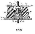
- the piston 86-87 moves in the chamber 85 partially or completely filled with damping material, while its upper part 83 moves in a chamber 89 filled with air, constituted by the frame 2 and a part 84 which is secured to it , comprising a central depression as well as an opening of dimension adapted to the sealed passage of the part 87 of the piston.
- the centering piece 90 is made of elastomer and has an upper edge 91 and a lower edge 92 which respectively bear on the frame 2 and the part 84.
- this part 90 prevents the piston 87 from abutting on the part 84, whatever the static load applied to the device; this would then cause high damping for vibrations of low amplitude, constituting a harmful phenomenon in itself.
- the aim is to perfect the seal between the central part 87 of the piston and the central opening of the part 84.
- the frustoconical support 100 of elastomer is extended by a zone 101 constituting a seal d 'tightness between the two previous parts.
- the seal 101 could be made of a material different from that of the support 100, insofar as its characteristics of low friction would be incompatible with the nature of the support 100 which has low dynamic stiffening. In this case, the seal 101 would be attached, for example clipped or glued to the edges of the opening of the part 84.
- centering piece 90 can, where appropriate, be adapted to the upper enlargement 83 of the piston, the latter possibly also having several enlargements such as 102, 103, insofar as the value is to be increased of its damping during its movement in the cavity 85.
Landscapes
- Engineering & Computer Science (AREA)
- General Engineering & Computer Science (AREA)
- Mechanical Engineering (AREA)
- Combined Devices Of Dampers And Springs (AREA)
Abstract
Description
- La présente invention se rapporte à un support élastique antivibratoire à dispositif amortissant incorporé, applicable notamment à la suspension de groupes motopropulseung de véhicules automobiles.
- On sait que de tels supports élastiques ont pour rôle principal de filtrer les vibrations dues aux imperfections d'équilibre du moteur. A ce titre, ces supports doivent présenter une grande souplesse. Malheureusement celle-ci conduit à une détérioration importante du confort sous l'effet des trépidations à basse fréquence, provenant de la route ; ces dernières sont transmises du fait d'un amortissement insuffisant des supports généralement réalisés en élastomère. En d'autres termes les caractéristiques souhaitées sont :
- - une rigidité statique bien définie, car le rôle premier d'un tel support est de porter la charge statique qui lui est appliquée ;
- - un certain amortissement, lors des sollicitations de fréquences basses de 10 à 20 Hertz et d'amplitudes fortes de l'ordre de 0,5 à 5 mm, afin de limiter les vibrations de la masse suspendue ;
- - une faible rigidification dynamique aux hautes fréquences de 50 à 300 Hertz environ, afin de conserver de bonnes caractéristiques de filtrage de ces vibrations, génératrices de bruit.
- Une des propriétés des matériaux visco-élastiques du type élastomère est l'augmentation du taux de rigidification dynamique avec la fréquence, donc la dégradation progressive du filtrage des vibrations. Cette augmentation est d'autant plus prononcée que le mélange est amortissant. Les progrès réalisés dans la formulation des mélanges aboutissent souvent à des compromis acceptables. Toutefois, il semble que l'on atteigne actuellement la limite des possibilités d'amélioration par ce moyen.
- On connait déjà des dispositifs permettant de séparer la fonction "amortissement" de la fonction "rigidité". L'un d'entre eux associe un support élastique souple à un amortisseur, mais cette solution est coûteuse et inefficace pour amortir des oscillations de faibles amplitudes, du fait des frottements mécaniques dans les amortisseurs. De plus, l'implantation des amortisseurs peut être particulièrement difficile dans le volume exigu d'un compartiment moteur.
- D'autres solutions consistent à incorporer au support lui-même un moyen d'amortissement hydraulique ou pneumatique en utilisant les déformations du support lui-même pour déplacer un fluide à travers un orifice. Ces solutions ne sont pas parfaitement satisfaisantes car elles ne prennent pas suffisamment en compte l'existence de vibrations d'amplitude différentes. De plus, ces dispositifs présentent généralement un encombrement important, n'apportent un gain d'amortissement que globalement suivant une seule direction de sollicitation et ne permettent pas l'obtention, généralement souhaitée par les constructeurs automobiles d'un rapport donné des rigidités suivant deux directions perpendiculaires.
- La présente invention, qui pallie les inconvénients ci-dessus, est essentiellement constituée d'une enceinte souple en élastomère assurant la fonction "rigidité" et d'un volume de matériau facilement déformable, du type pâte à modeler, qui assure la fonction "amortissement".
- Ce matériau, que l'on appellera désormais "matériau amortissant" dissipe au moins partiellement l'énergie incidente nécessaire à sa déformation, qui peut se reproduire un nombre quasi-infini de fois, sams entrainer sa dégradation.
- L'invention sera décrite au regard des figures 1 à 10 ci-jointes, qui représentent à titre non limitatif :
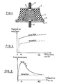
- - figure 1 : une coupe transversale d'une réalisation de l'invention ;
- - figure 2 et 3 : deux courbes montrant l'incidence du matériau amortissant sur la rigidité et l'amortissement en fonction des fréquences ;
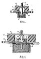
- - figure 4 : une première variante de l'invention, une vue en coupe transversale ;
- - figure 5 : un détail de la figure précédente, vue en coupe, montrant une modification d'un des éléments de dispositif ;
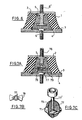
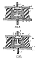
- - figure 6 à 10 : des vues analogues d'un second type de variantes.
- En se rapportant à la figure 1, on voit que le support élastique antivibratoire selon l'invention est essentiellement constitué d'un bloc 1 tronconique, creux en élastomère, adhérisé lors de sa vulcanisation aux armatures rigides 2 et 3. Une armature inférieure complémentaire 4 est liée solidement et hermétiquement à l'armature 3. Les armatures 2 et 4 comportent des éléments mécaniques permettant la fixation du support à son poste de travail. Ces éléments mécaniques peuvent être des vis 6 soudée comme dans le cas de la figure 1. La chambre étanche 5 ainsi constituée est remplie totalement ou partiellement d'un volume de matériau amortissant.
- Ce matériau possède une viscosité dynamique comprise entre 10-2 et 10 33 Poiseuille à température ambiante.
- De bons résultats ont été obtenus par exemple avec le matériau dénommé "Gomme GSIR" distribué par la Société RHONE-POULENC.
- Le matériau amortissant peut aussi être un fluide non newtonien et parmi ceux-ci certains peuvent avoir des propriétés thixotropiques ou rhéopexique. Par exemple, on pourra utiliser une dissolution de polyméthacrylate de méthyle dans une huile de synthèse appropriée ; ou un matériau comprenant au moins une phase liquide formée d'huile de silicone, de polyglycol, d'huile minérale et/ou d'un ester d'acide carbonique aliphatique ou aromatique, saturé, auquel est ajouté du graphite broyé et au moins un agent mouillant.
- Un autre matériau amortissant conforme à l'invention est constitué d'une dispersion visqueuse non newtonienne comportant une huile de type silicone, de viscosité comprise entre 10 et 104 poiseuille à température ambiante et de billes de verre qui sont uniformément réparties, dont la granulométrie est comprise entre 40 et 90 microns- Le rapport des masses de ces billes de verre sur l'huile au silicone est de l'ordre de 3 à 8.
- Dans le cas de ce matériau, la dissipation d'énergie recherchée résulte des frottements des billes de verre les unes contre les autres, déterminant de ce fait un certain amortissement des vibrations issues du moteuro
- Ce remplissage s'effectue avant ou après fixation de l'armature 4 sur l'armature 3. Dans ce dernier cas, au moins une des armatures 2 ou 4 doit être munie d'un dispositif permettant le remplissage de la chambre 5, par exemple un orifice, qui doit assurer une étanchéité parfaite de la chambre 5 après remplissage.
- Le support qui vient d'être décrit fonctionne de la façon suivante : Les déformations de caoutchouc 1 s'effectuant à volume constant, tout déplacement relatif des armatures 2-3 entraine une déformation de la géométrie de la chambre 5 et par conséquence du matériau amortissant qu'elle contient, d'où un gain appréciable, sur la valeur de l'amortissement.
- On voit immédiatement que la valeur de ce gain dépend :
- - de l'amplitude du déplacement considéré ;
- - du matériau amortissant utilisé, particulièrement de sa plus ou moins grande incompressibilité et de sa qualité amortissante pour un déplacement donné ;
- - de la géométrie du bloc en élastomère. Les essais ont montré que celle-ci a une importance considérable.
- On remarquera que le dispositif ci-dessus présente bien les avantages suivants :
- - son encombrement est identique à celui des supports "tout caoutchouc" utilisés actuellement ;
- - il apporte un gain d'amortissement quelle que soit la direction de la sollicitation ;
- - sa rigidification dynamique est sensiblement égale à celle du bloc en élastomère, sous réserve de choisir convenablement le matériau amortissant et la géométrie du bloc 1.
- En effet, on comprend bien que le gain d'amortissement est très faible voire nul pour de très faibles amplitudes de vibrations puisque celles-ci n'entraînent que de très faibles déformations de la chambre 5.
- - il permet d'obtenir un rapport donné de rigidités suivant deux directions perpendiculaires aussi facilement qu'avec les supports "tout caoutchouc" utilisés actuellement ;
- - sa simplicité garantit sa fiabilité ;
- - sa réalisation industrielle est aisée et moins coûteuse que celle des solutions connues à ce jour.
- Pour illustrer ce qui précède, on a représenté aux figures 2 et 3, un schéma comparatif des réponses en fréquence du dispositif avec ou sans marériau amortissant. le
- - la figure 2 met en évidence que la présence de matériau amortissant dans le support entraine une augmentation de rigidité du dispositif et ce, quelle que soit la fréquence. Cependant, ce gain de rigidité étant quasi-constant quelle que soit la fréquence d'excitation, il en découle que les deux courbes ont des pentes quasi-identiques et par conséquent, le matériau amortissant n'entraine pas ou peu d'augmentation du taux de rigidification dynamique communément caractérisé par :

- Une amélioration du dispositif ci-dessus est visible à la figure 4. Selon cette variante, le support comprend un bloc en élastomère 41 adhérisé lors de sa vulcanisation aux armatures 42 et 43. Un élément en élastomère 45 est lié solidement et hermétiquement à un élément 46 appelé "piston", par exemple par adhérisation lors de la vulcanisation de l'élément 45. Cet ensemble (45, 46) est lié solidement et hermétiquement à l'armature 42, par tout moyen connu, tel que sertissage, etc... Un boîtier 44 est fixé à l'armature 43 en exerçant une contrainte perma- manente sur l'élément 45. On constitue ainsi une chambre étanche 47 que l'on remplit comme précédemment d'un matériau amortissant. La chambre 48 est étanche et remplie d'air. Le support de la figure 4 fonctionne de la façon suivante :
- Tout déplacement relatif des armatures 42 et 43 entraine un déplacement relatif du piston 46 dans la chambre 47 et par conséquent une déformation du matériau amortissant.
- Les avantages de ce dispositif par rapport à celui de la figure 1 sont les suivants :
- - Une valeur plus élevée du gain d'amortissement : En effet, pour un déplacement relatif donné des armatures 42 et 43, la déformation du matériau amortissant est beaucoup plus importante, sous réserve de bien choisir la géométrie de l'élément 46 présent dans la chambre 47.
- - Une dispersion plus faible sur l'amortissement : Elle est obtenue compte tenu des plus faibles dispersions dimensionnelles des éléments métalliques (44 et 46) par rapport aux éléments caoutchouc homologues de la figure 1. En effet, il est bien connu que, notamment, en ce qui concerne la rigidité d'un élément caoutchouc, la réalisation en série ne peut la respecter qu'a - 15 %. Il en découle donc des dispersions importantes de la variation géométrique de la chambre 5 des dispositifs du type de la figure 1, pour un déplacement relatif donné des armatures 2 et 3. Avec les dispositifs du type de la figure 2, on élimine cet inconvénient puisque la chambre 47 et le piston 46 sont essentiellement rigides.
- On utilisera de préférence le dispositif du type de la figure 2, lorsque l'on recherchera des valeurs très élevées d'amortissement. Ce résultat sera obtenu en choisissant la géométrie du piston 46 de façon à ce que la déformation du matériau absorbant soit maximale pour un déplacement relatif donné des armatures 42 et 43. Dans ce cas, l'amortissement sera important même si ce déplacement relatif est de très faible amplitude ; ceci entraine donc une rigidité élevée pour des vibrations à haute fréquence et par conséquent une légère dégradation du confort acoustique.
- Pour remédier à cet inconvénient, on améliorera cette première variante de l'invention en la modifiant dans le sens de la figure 5 selon laquelle le piston 46 de la figure 4 est remplacé par un dispositif appelé "piston filtré", qui autorise des déplacements relatifs des parties 51-52 sans que le piston 53 ne déforme le matériau amortissant, ces déplacements relatifs étant étroitement liés au jeu mécanique, choisi arbitrairement, et réalisé lors de l'assemblage des parties 51 et 52.
- Selon cette réalisation, le piston 46 et sa tige de maintient constituant une seule pièce, selon la figure 4, sont fractionnées en trois parties, respectivement 53, 52 et 51. Le piston proprement dit figuré par la partie 53, ainsi que la partie 52 qui lui fait face sont adhéri- sés à l'élément en élastomère 45 au moment de sa vulcanisation.
- La partie 52 constitue un container dont les rebords seront sertis, après introduction de la partie 51 de maintien à l'armature 42, évitant ainsi son dégagement ultérieur. La base de ladite partie 51 présente un évasement sur les faces duquel sont liées des cales en élastomère 55-56 destinées à assurer le centrage des deux parties 52-51.
- Le dispositif ci-dessus autorise donc de faibles déplacements relatifs des parties 51-52 sans que le piston 53 ne déforme le matériau amortissant, d'où un faible amotissement et par suite une basse rigidité à haute fréquence. Par contre, pour des déplacements plus importants (par exemple supérieurs à 0,2 mm) les cales en élastomère 55 et 56 s'aplatissent. L'évasement inférieur de la partie 51 étant alors en butée sur la partie 52, l'entraine dans son déplacement, déformant alors le matériau amortissant par l'intermédiaire de l'élément 53, ce qui détermine ainsi un amortissement élevé.
- La disposition des figures 6 à 10 est une synthèse des variantes décrites aus figures 1 et 4-5, apportant des avantages de compacité.
- Ainsi, on retrouve à la figure 6 le bloc tronconique creux 1 en élastomère, adhérisé lors de sa vulcanisation aux armatures rigides 2-3, l'armature inférieure complémentaire 4 et les éléments de fixation 6.
- De la même façon, le volume creux 5 rempli totalement ou partiellement du matériau amortissant.
- Cependant, on remarquera dans ce volume la présence du piston 46 de la figure 4 travaillant comme dans le cas de cette figure, mais logé à l'intérieur du dispositif en élastomère, ce qui naturellement permet de gagner en compacité par rapport à la figure 4, du fait de l'absence du boîtier 44.
- La variante de la figure précédente illustrée aux figures 7a et 7b porte essentiellement sur le piston. Sa base 77, réalisée de préférence en matière synthétique et, bien que monobloc, est constituée de trois parties à savoir deux butées 78 et un éléement 79 centré entre ces butées et destiné à déformer le matériau amortissant. La géométrie et l'épaisseur de cet élément central 79 sont choisis de façon à ce qu'il fléchisse lorsqu'on lui applique une force (voir figure 7b). L'élément 77 est lié solidement à la queue de l'élément 76 (par moulage, collage, soudage par friction), ce cernier étant hermétiquement fixé à l'armature 2.
- Le support ainsi réalisé fonctionne de la façon suivante : lors d'un déplacement relatif de faible amplitude de l'armature 2 par rapport à l'armature 3, l'élément central 79 de faible épaisseur fléchit sous la force résistante due au matériau absorbant ; ceci entraine peu de déformation de ce dernier et par conséquent peu d'amortissement, donc peu de rigidification. Par contre lorsque ces déplacements ont des am- .plitudes plus importantes, l'élément 79 de faible épaisseur vient au contact des butées 78 prévues à cet effet, qui se déplacent à leur tour dans le matériau amortissant, d'où un amortissement élevé.
- La représentation de la figure 7c constitue une variante du dispositif précédent. La base 77 du piston, de préférence en matière synthétique comporte trois disques 71-72-73 positionnés selon trois plans perpendiculaires. Le croisillon ainsi obtenu permet un gain d'amortissement quasi-identique dans toutes les directions et notamment en cisaillement.
- La réalisation de ces dispositifs est peu coûteuse mais présente.. des limites, car on voit que le piston déforme le matériau amortissant même pour de très faibles déplacements relatifs des armatures 2-3.
- D'autres dispositifs vont maintenant être décrits qui pallient l'inconvénient précédent. Selon ces systèmes, le--piston du type "filtré" ne peut se déplacer, et donc déformer le matériau amortissant que s'il est en contact avec les butées prévues à cet effet. En l'absence de ce contact, la seule déformation que peut subir le matériau amortissant est celle qui résulte de la déformation de la chambre 5.
- La réalisation de la figure 8 permet de désolidariser le piston 87 du dispositif élastique 1-2-3-4 pour les vibrations de faibles amplitudes.
- Le piston 87 possède un élargissement supérieur 83 bordé par une couronne 88 d'un matériau assurant un contact silencieux lorsque cette pièce vient butée, et un élargisssment inférieur 86 de préférence en matière synthétique obtenue par moulage, permettant ainsi la réalisation de géo- mètrie très variées, les pièces 86 et 87 étant solidarisées notamment par soudage par friction.
- Le piston 86-87 se déplace dans la chambre 85 remplie partiellement ou totalement de matériau amortissant, tandis que sa partie supérieure 83 se meut dans une chambre 89 remplie d'air, constituée par l'armature 2 et une pièce 84 qui lui est solidarisée, comportant une dépression centrale ainsi qu'une ouverture de dimension adaptée au passage étanche de la partie 87 du piston.
- La précision d'usinage de ladite ouverture ainsi que l'utilisation éventuelle de matériaux anti-friction adéquats pour l'une ou les deux pièces ci-dessus permettent d'optimiser le filtrage des vibrations de faibles amplitudes. L'étanchéité entre ces deux pièces est encore améliorée selon la réalisation de la figure 9 qui ne diffère du dispositif précédent que par la présence d'une pièce de centrage 90 disposée sur l'élargissement supérieur 83 du piston 87, à la place de la couronne 88.
- La pièce de centrage 90 est en élastomère et présente une bordure supérieure 91 et une bordure inférieure 92 prenant respectivement appui sur l'armature 2 et la pièce 84.
- La structure particulière de cette pièce 90 évite que le piston 87 vienne en butée sur la pièce 84, quelle que soit la charge statique appliquée au dispositif ; ceci entrainerait alors un amortissement élevé pour les vibrations de faible amplitude, bonstituant un phénomène nuisible en soi.
- Selon la figure 10, on s'attache à parfaire l'étanchéité entre la partie centrale 87 du piston et l'ouverture centrale de la pièce 84. On constate que le support tronconique 100 en élastomère se prolonge par une zone 101 constituant un joint d'étanchéité entre les deux pièces précédentes. On remarquera que le joint 101 pourrait être en un matériau différent de celui du support 100, dans la mesure où ses caractéristiques de faible frottement seraient incompatibles avec la nature du support 100 qui présente une faible rigidification dynamique. Dans ce cas, le joint 101 serait rapporté, par exemple clipsé ou collé sur les bords de l'ouverture de la pièce 84.
- Notons encore que la pièce de centrage 90 peut, le cas échéant, être adaptée sur l'élargissement supérieur 83 du piston, ce dernier pouvant par ailleurs présenter plusieurs élargidsements tels que 102, 103, dans la mesure où l'on veut augmenter la valeur de son amortissement lors de son déplacement dans la cavité 85.
Claims (16)
Applications Claiming Priority (2)
| Application Number | Priority Date | Filing Date | Title |
|---|---|---|---|
| FR8216279 | 1982-09-28 | ||
| FR8216279A FR2533506B1 (fr) | 1982-09-28 | 1982-09-28 | Support elastique antivibratoire |
Publications (2)
| Publication Number | Publication Date |
|---|---|
| EP0105794A1 true EP0105794A1 (fr) | 1984-04-18 |
| EP0105794B1 EP0105794B1 (fr) | 1986-08-13 |
Family
ID=9277796
Family Applications (1)
| Application Number | Title | Priority Date | Filing Date |
|---|---|---|---|
| EP83401882A Expired EP0105794B1 (fr) | 1982-09-28 | 1983-09-27 | Support élastique antivibratoire |
Country Status (5)
| Country | Link |
|---|---|
| US (1) | US4576366A (fr) |
| EP (1) | EP0105794B1 (fr) |
| DE (1) | DE3365317D1 (fr) |
| FR (1) | FR2533506B1 (fr) |
| PT (1) | PT77407B (fr) |
Cited By (7)
| Publication number | Priority date | Publication date | Assignee | Title |
|---|---|---|---|---|
| FR2554889A1 (fr) * | 1983-11-16 | 1985-05-17 | Gomma Antivibranti Applic | Support-moteur pour vehicule |
| FR2572338A1 (fr) * | 1984-10-30 | 1986-05-02 | Ouest Cie | Attache elastique d'amortisseur |
| EP0221432A1 (fr) * | 1985-10-28 | 1987-05-13 | Continental Aktiengesellschaft | Support élastique à amortissement hydraulique |
| EP0245111A3 (en) * | 1986-05-09 | 1988-12-14 | Kabushiki Kaisha Cubic Engineering | A bellow type shock absorber |
| EP0268785A3 (fr) * | 1986-11-26 | 1990-01-31 | Continental Aktiengesellschaft | Support élastique à amortissement hydraulique |
| US4974820A (en) * | 1986-05-09 | 1990-12-04 | Suzuki Sogyo Kabushiki Kaisha | Bellows type shock absorber |
| EP3098472A1 (fr) * | 2015-05-27 | 2016-11-30 | Toyo Tire&Rubber Co., Ltd. | Bouchon pour système de suspension |
Families Citing this family (25)
| Publication number | Priority date | Publication date | Assignee | Title |
|---|---|---|---|---|
| DE3410669A1 (de) * | 1984-03-23 | 1985-10-24 | Metabowerke GmbH & Co, 7440 Nürtingen | Daempfungselement und dessen einbau in ein motorisch angetriebenes handwerkzeug |
| DE3432768A1 (de) * | 1984-09-06 | 1986-03-13 | Adam Opel AG, 6090 Rüsselsheim | Gummimetallager |
| US4790521A (en) * | 1985-10-03 | 1988-12-13 | Nissan Motor Company, Limited | Anti-vibration apparatus for mounting a power unit on a supporting body with suppression of vibrations |
| US4881724A (en) * | 1987-08-07 | 1989-11-21 | General Motors Corporation | Flexible mounting for engines, machine assemblies and the like |
| IT1237779B (it) * | 1989-11-20 | 1993-06-17 | Pirelli Sistemi Antivibranti | Supporto motore. |
| US5286013A (en) * | 1990-11-13 | 1994-02-15 | General Electric Company | Vibration damper assembly |
| CH681915A5 (fr) * | 1991-04-26 | 1993-06-15 | Mettler Toledo Ag | |
| DE4139049C2 (de) * | 1991-11-27 | 1994-03-03 | Metzeler Gimetall Ag | Elastisches Motorlager |
| JPH0712167A (ja) * | 1993-06-24 | 1995-01-17 | Hitachi Ltd | 振動制御装置、洗濯機、コンプレッサ、配管系および空調機 |
| GB2304171A (en) * | 1995-08-08 | 1997-03-12 | Btr Antivibration Syst Inc | Viscous fluid mount |
| US5869164A (en) * | 1995-11-08 | 1999-02-09 | Rik Medical Llc | Pressure-compensating compositions and pads made therefrom |
| US5855260A (en) * | 1996-12-13 | 1999-01-05 | The Aerospace Corporation | Tuned broadband particulate vibration absorber |
| US6929084B2 (en) * | 2001-06-29 | 2005-08-16 | Meritor Heavy Vehicle Technology, Llc | Suspension module for use with an independent suspension including semi-trailing arms with airbag supports |
| RU2236618C1 (ru) * | 2003-03-17 | 2004-09-20 | Ткачев Виктор Петрович | Энергопоглощающее устройство |
| US6955250B2 (en) * | 2003-12-03 | 2005-10-18 | Honeywell International Inc. | Apparatus for damping vibration using macro particulates |
| JP2008144789A (ja) * | 2006-12-06 | 2008-06-26 | Yamaha Motor Co Ltd | 液圧緩衝器 |
| CN104196955A (zh) * | 2014-08-27 | 2014-12-10 | 武汉科技大学 | 一种发动机颗粒阻尼橡胶隔振器 |
| DE102014219338A1 (de) | 2014-09-24 | 2016-03-24 | Bayerische Motoren Werke Aktiengesellschaft | Elastomere Zusatzfeder in der Radaufhängung eines Fahrzeugs |
| US10570980B2 (en) * | 2016-05-23 | 2020-02-25 | Vibracoustic North America L.P. | Particle damper system and method |
| US20200063821A1 (en) * | 2017-03-17 | 2020-02-27 | Vibracoustic North America L.P. | Damping component with non-newtonian insert |
| EP3645908B1 (fr) * | 2017-06-26 | 2025-02-26 | HRL Laboratories, LLC | Isolateur de vibrations de fluide et d'élastomère |
| RU185341U1 (ru) * | 2018-05-21 | 2018-11-30 | Федеральное государственное бюджетное образовательное учреждение высшего образования "Саратовский государственный технический университет имени Гагарина Ю.А." (СГТУ имени Гагарина Ю.А.) | Комбинированный упругий элемент для систем демпфирования |
| RU191235U1 (ru) * | 2019-02-18 | 2019-07-30 | Федеральное государственное бюджетное образовательное учреждение высшего образования "Саратовский государственный технический университет имени Гагарина Ю.А." (СГТУ имени Гагарина Ю.А.) | Комбинированный упругий элемент для систем демпфирования |
| JP7029433B2 (ja) * | 2019-10-11 | 2022-03-03 | 本田技研工業株式会社 | 車両用防振装置 |
| FR3105101B1 (fr) * | 2019-12-18 | 2021-11-26 | Valeo Systemes Thermiques | Element de decouplage pour un support de moteur comprenant un fluide non newtonien |
Citations (12)
| Publication number | Priority date | Publication date | Assignee | Title |
|---|---|---|---|---|
| FR2218508A1 (fr) * | 1973-02-19 | 1974-09-13 | Pineau Andre | |
| DE2454834A1 (de) * | 1974-11-19 | 1976-05-20 | Kaspar Lochner | Vorrichtung zum daempfen von mechanischen, sowie zum unterdruecken von akustischen schwingungen |
| CH577126A5 (en) * | 1972-12-21 | 1976-06-30 | Arfina Anstalt Finanz | Vibration damping isolating mount for engines - are similar are effective in three orthogonal planes and have silicone inside domed cover |
| DE2533088A1 (de) * | 1975-07-24 | 1977-02-03 | Volkswagenwerk Ag | Vorrichtung zur vernichtung von stossenergie |
| FR2348401A1 (fr) * | 1976-04-14 | 1977-11-10 | Rhone Poulenc Ind | Ressorts auto-amortisseurs a compression hydrostatique de caoutchoucs silicones non vulcanises |
| DE2712641A1 (de) * | 1977-03-23 | 1978-09-28 | Phoenix Gummiwerke Ag | Elastisches lager fuer kraftfahrzeugmotore |
| DE2717825A1 (de) * | 1977-04-21 | 1978-10-26 | Kaspar Lochner | Dreidimensional wirkendes daempfelement |
| DE2730046A1 (de) * | 1977-04-21 | 1979-01-11 | Kaspar Lochner | Vorrichtung zur aufnahme von statischen und dynamischen lasten sowie daempfung von schwingungen unterschiedlicher frequenz und amplituden, insbesondere zur lagerung von verbrennungsmotoren, maschinen u.dgl. |
| FR2451511A1 (fr) * | 1979-03-12 | 1980-10-10 | Eurovib Grpt Interet Eco | Dispositif de suspension |
| GB2055172A (en) * | 1979-06-29 | 1981-02-25 | Gomma Antivibranti Applic | Elastomeric mounting with fluid damping of high amplitude oscillations |
| GB2079894A (en) * | 1980-07-04 | 1982-01-27 | Gomma Antivibranti Applic | Damped resilient support device |
| EP0059936A1 (fr) * | 1981-03-03 | 1982-09-15 | Schiedel GmbH & Co. | Agent d'amortissement pâteux, procédés pour sa préparation et son utilisation |
Family Cites Families (11)
| Publication number | Priority date | Publication date | Assignee | Title |
|---|---|---|---|---|
| DE1303290B (fr) * | 1965-11-17 | Lord Corp | ||
| FR1570498A (fr) * | 1968-01-31 | 1969-06-13 | ||
| US4005858A (en) * | 1973-08-31 | 1977-02-01 | Kaspar Lochner | Damping member |
| DE2503581A1 (de) * | 1975-01-29 | 1976-08-05 | Kaspar Lochner | Vorrichtung zum daempfen von mechanischen sowie zum unterdruecken von akustischen schwingungen |
| US4182441A (en) * | 1977-03-11 | 1980-01-08 | Lagrou Donald J | Pipe snubber including reservoir and seal structure |
| JPS5530563A (en) * | 1978-08-28 | 1980-03-04 | Bridgestone Corp | Vibration-proof support |
| JPS55123032A (en) * | 1979-03-12 | 1980-09-22 | Aisin Seiki Co Ltd | Device for insulating vibration |
| FR2456260A1 (fr) * | 1979-05-11 | 1980-12-05 | Hutchinson Mapa | Perfectionnements apportes aux supports elastiques a base d'elastomeres |
| JPS6015806B2 (ja) * | 1980-04-14 | 1985-04-22 | 日産自動車株式会社 | ダンパ付エンジンマウント装置 |
| US4342446A (en) * | 1980-11-18 | 1982-08-03 | Gould Inc. | Self-leveling viscous elastic damper |
| JPS57127141A (en) * | 1981-01-30 | 1982-08-07 | Sanwa Tekki Corp | Multi-direction vibration-proof device |
-
1982
- 1982-09-28 FR FR8216279A patent/FR2533506B1/fr not_active Expired
-
1983
- 1983-09-27 EP EP83401882A patent/EP0105794B1/fr not_active Expired
- 1983-09-27 DE DE8383401882T patent/DE3365317D1/de not_active Expired
- 1983-09-28 US US06/536,649 patent/US4576366A/en not_active Expired - Fee Related
- 1983-09-28 PT PT77407A patent/PT77407B/fr unknown
Patent Citations (12)
| Publication number | Priority date | Publication date | Assignee | Title |
|---|---|---|---|---|
| CH577126A5 (en) * | 1972-12-21 | 1976-06-30 | Arfina Anstalt Finanz | Vibration damping isolating mount for engines - are similar are effective in three orthogonal planes and have silicone inside domed cover |
| FR2218508A1 (fr) * | 1973-02-19 | 1974-09-13 | Pineau Andre | |
| DE2454834A1 (de) * | 1974-11-19 | 1976-05-20 | Kaspar Lochner | Vorrichtung zum daempfen von mechanischen, sowie zum unterdruecken von akustischen schwingungen |
| DE2533088A1 (de) * | 1975-07-24 | 1977-02-03 | Volkswagenwerk Ag | Vorrichtung zur vernichtung von stossenergie |
| FR2348401A1 (fr) * | 1976-04-14 | 1977-11-10 | Rhone Poulenc Ind | Ressorts auto-amortisseurs a compression hydrostatique de caoutchoucs silicones non vulcanises |
| DE2712641A1 (de) * | 1977-03-23 | 1978-09-28 | Phoenix Gummiwerke Ag | Elastisches lager fuer kraftfahrzeugmotore |
| DE2717825A1 (de) * | 1977-04-21 | 1978-10-26 | Kaspar Lochner | Dreidimensional wirkendes daempfelement |
| DE2730046A1 (de) * | 1977-04-21 | 1979-01-11 | Kaspar Lochner | Vorrichtung zur aufnahme von statischen und dynamischen lasten sowie daempfung von schwingungen unterschiedlicher frequenz und amplituden, insbesondere zur lagerung von verbrennungsmotoren, maschinen u.dgl. |
| FR2451511A1 (fr) * | 1979-03-12 | 1980-10-10 | Eurovib Grpt Interet Eco | Dispositif de suspension |
| GB2055172A (en) * | 1979-06-29 | 1981-02-25 | Gomma Antivibranti Applic | Elastomeric mounting with fluid damping of high amplitude oscillations |
| GB2079894A (en) * | 1980-07-04 | 1982-01-27 | Gomma Antivibranti Applic | Damped resilient support device |
| EP0059936A1 (fr) * | 1981-03-03 | 1982-09-15 | Schiedel GmbH & Co. | Agent d'amortissement pâteux, procédés pour sa préparation et son utilisation |
Non-Patent Citations (3)
| Title |
|---|
| PATENTS ABSTRACTS OF JAPAN, vol. 4, no. 171 (M-44)[653], 26 novembre 1980 * |
| PATENTS ABSTRACTS OF JAPAN, vol. 4, no. 64 (M-11)[546], 14 mai 1980, page 134 M 11 * |
| PATENTS ABSTRACTS OF JAPAN, vol. 6, no. 224 (M-170)[1102], 9 novembre 1982 * |
Cited By (8)
| Publication number | Priority date | Publication date | Assignee | Title |
|---|---|---|---|---|
| FR2554889A1 (fr) * | 1983-11-16 | 1985-05-17 | Gomma Antivibranti Applic | Support-moteur pour vehicule |
| FR2572338A1 (fr) * | 1984-10-30 | 1986-05-02 | Ouest Cie | Attache elastique d'amortisseur |
| EP0221432A1 (fr) * | 1985-10-28 | 1987-05-13 | Continental Aktiengesellschaft | Support élastique à amortissement hydraulique |
| EP0245111A3 (en) * | 1986-05-09 | 1988-12-14 | Kabushiki Kaisha Cubic Engineering | A bellow type shock absorber |
| US4856626A (en) * | 1986-05-09 | 1989-08-15 | Kabushiki Kaisha Cubic Engineering | Bellows type shock absorber |
| US4974820A (en) * | 1986-05-09 | 1990-12-04 | Suzuki Sogyo Kabushiki Kaisha | Bellows type shock absorber |
| EP0268785A3 (fr) * | 1986-11-26 | 1990-01-31 | Continental Aktiengesellschaft | Support élastique à amortissement hydraulique |
| EP3098472A1 (fr) * | 2015-05-27 | 2016-11-30 | Toyo Tire&Rubber Co., Ltd. | Bouchon pour système de suspension |
Also Published As
| Publication number | Publication date |
|---|---|
| PT77407B (fr) | 1986-02-13 |
| EP0105794B1 (fr) | 1986-08-13 |
| US4576366A (en) | 1986-03-18 |
| FR2533506A1 (fr) | 1984-03-30 |
| FR2533506B1 (fr) | 1987-06-26 |
| PT77407A (fr) | 1983-10-01 |
| DE3365317D1 (en) | 1986-09-18 |
Similar Documents
| Publication | Publication Date | Title |
|---|---|---|
| EP0105794A1 (fr) | Support élastique antivibratoire | |
| EP0490724A1 (fr) | Attache hydroélastique de suspension et biélette de liaison élastique liée à cette attache | |
| EP0006819B1 (fr) | Dispositif de suspension, notamment de moteur d'un véhicule automobile | |
| CA1287826C (fr) | Dispositif d'isolation antivibratoire a amortissement hydraulique de l'elasticite radiale et procedes de realisation d'un tel dispositif | |
| FR2563880A1 (fr) | Dispositif amortisseur hydraulique | |
| FR2492026A1 (fr) | Dispositif porteur en caoutchouc possedant une capacite d'amortissement pneumatique | |
| FR2615260A1 (fr) | Dispositif, rempli de fluide, isolant aux vibrations | |
| FR2601740A1 (fr) | Manchonnage elastique a remplissage de fluide | |
| FR2486183A1 (fr) | Support amortisseur pour la suspension d'un corps oscillant a une structure de support | |
| FR2664667A1 (fr) | Dispositif d'amortissement de vibrations. | |
| EP0481836A1 (fr) | Dispositif de tension d'un galet tendeur pour transmission par lien souple, fonctionnant par déformation élastique d'un solide parallélépipédique déformable | |
| FR2555688A1 (fr) | Support elastique a faible raideur, notamment pour vehicule automobile | |
| FR3036150B1 (fr) | Dispositif d'amortissement d'oscillations de torsion | |
| FR2797482A1 (fr) | Dispositif amortisseur de vibrations presentant une grande durabilite du corps elastique | |
| FR2670262A1 (fr) | Cale hydroelastique. | |
| FR2572338A1 (fr) | Attache elastique d'amortisseur | |
| EP0236161B1 (fr) | Cale hydroélastique à suspension centrale, notamment pour la suspension d'un groupe motopropulseur de véhicule automobile | |
| EP3076245B1 (fr) | Dispositif amortisseur notamment pour composant micromécanique horloger | |
| FR2602292A1 (fr) | Perfectionnements aux supports amortisseurs hydrauliques | |
| FR2973463A1 (fr) | Dispositif d'amortissement de vibration rempli de fluide du type a amortissement de vibration multidirectionnel | |
| FR2555273A1 (fr) | Perfectionnements apportes aux supports antivibratoires hydrauliques | |
| EP3719587A1 (fr) | Dispositif antichoc et oscillateur mécanique horloger à guidage flexible disposant d'un tel dispositif antichoc | |
| EP1170520A2 (fr) | Palier de roulement muni d'un amortisseur de type "squeeze film" | |
| EP0265309A1 (fr) | Dispositif de commande de vibrateur | |
| EP1584837B1 (fr) | Dispositif antivibratoire |
Legal Events
| Date | Code | Title | Description |
|---|---|---|---|
| PUAI | Public reference made under article 153(3) epc to a published international application that has entered the european phase |
Free format text: ORIGINAL CODE: 0009012 |
|
| 17P | Request for examination filed |
Effective date: 19830930 |
|
| AK | Designated contracting states |
Designated state(s): BE DE FR GB IT NL SE |
|
| GRAA | (expected) grant |
Free format text: ORIGINAL CODE: 0009210 |
|
| AK | Designated contracting states |
Kind code of ref document: B1 Designated state(s): BE DE FR GB IT NL SE |
|
| ITF | It: translation for a ep patent filed | ||
| REF | Corresponds to: |
Ref document number: 3365317 Country of ref document: DE Date of ref document: 19860918 |
|
| PLBE | No opposition filed within time limit |
Free format text: ORIGINAL CODE: 0009261 |
|
| STAA | Information on the status of an ep patent application or granted ep patent |
Free format text: STATUS: NO OPPOSITION FILED WITHIN TIME LIMIT |
|
| 26N | No opposition filed | ||
| PGFP | Annual fee paid to national office [announced via postgrant information from national office to epo] |
Ref country code: NL Payment date: 19870930 Year of fee payment: 5 |
|
| PG25 | Lapsed in a contracting state [announced via postgrant information from national office to epo] |
Ref country code: GB Effective date: 19890927 |
|
| PG25 | Lapsed in a contracting state [announced via postgrant information from national office to epo] |
Ref country code: SE Effective date: 19890928 |
|
| PG25 | Lapsed in a contracting state [announced via postgrant information from national office to epo] |
Ref country code: NL Effective date: 19900401 |
|
| NLV4 | Nl: lapsed or anulled due to non-payment of the annual fee | ||
| GBPC | Gb: european patent ceased through non-payment of renewal fee | ||
| PGFP | Annual fee paid to national office [announced via postgrant information from national office to epo] |
Ref country code: DE Payment date: 19900818 Year of fee payment: 8 |
|
| PGFP | Annual fee paid to national office [announced via postgrant information from national office to epo] |
Ref country code: BE Payment date: 19900821 Year of fee payment: 8 |
|
| PG25 | Lapsed in a contracting state [announced via postgrant information from national office to epo] |
Ref country code: BE Effective date: 19910930 |
|
| BERE | Be: lapsed |
Owner name: CIE DES PRODUITS INDUSTRIELS DE L'OUEST CPIO Effective date: 19910930 |
|
| PG25 | Lapsed in a contracting state [announced via postgrant information from national office to epo] |
Ref country code: DE Effective date: 19920602 |
|
| EUG | Se: european patent has lapsed |
Ref document number: 83401882.2 Effective date: 19900521 |
|
| PGFP | Annual fee paid to national office [announced via postgrant information from national office to epo] |
Ref country code: FR Payment date: 20000118 Year of fee payment: 17 |
|
| PG25 | Lapsed in a contracting state [announced via postgrant information from national office to epo] |
Ref country code: FR Free format text: LAPSE BECAUSE OF NON-PAYMENT OF DUE FEES Effective date: 20010531 |
|
| REG | Reference to a national code |
Ref country code: FR Ref legal event code: ST |