EP0105867A2 - Equipement pour déterminer la position de la tête d'abattage d'une machine de creusement ou d'extraction - Google Patents
Equipement pour déterminer la position de la tête d'abattage d'une machine de creusement ou d'extraction Download PDFInfo
- Publication number
- EP0105867A2 EP0105867A2 EP83890168A EP83890168A EP0105867A2 EP 0105867 A2 EP0105867 A2 EP 0105867A2 EP 83890168 A EP83890168 A EP 83890168A EP 83890168 A EP83890168 A EP 83890168A EP 0105867 A2 EP0105867 A2 EP 0105867A2
- Authority
- EP
- European Patent Office
- Prior art keywords
- cutting head
- receiver
- distance
- cutting
- transmitter
- Prior art date
- Legal status (The legal status is an assumption and is not a legal conclusion. Google has not performed a legal analysis and makes no representation as to the accuracy of the status listed.)
- Granted
Links
Images


Classifications
-
- E—FIXED CONSTRUCTIONS
- E21—EARTH OR ROCK DRILLING; MINING
- E21D—SHAFTS; TUNNELS; GALLERIES; LARGE UNDERGROUND CHAMBERS
- E21D9/00—Tunnels or galleries, with or without linings; Methods or apparatus for making thereof; Layout of tunnels or galleries
- E21D9/003—Arrangement of measuring or indicating devices for use during driving of tunnels, e.g. for guiding machines
-
- E—FIXED CONSTRUCTIONS
- E21—EARTH OR ROCK DRILLING; MINING
- E21C—MINING OR QUARRYING
- E21C35/00—Details of, or accessories for, machines for slitting or completely freeing the mineral from the seam, not provided for in groups E21C25/00 - E21C33/00, E21C37/00 or E21C39/00
- E21C35/302—Measuring, signaling or indicating specially adapted for machines for slitting or completely freeing the mineral
-
- E—FIXED CONSTRUCTIONS
- E21—EARTH OR ROCK DRILLING; MINING
- E21F—SAFETY DEVICES, TRANSPORT, FILLING-UP, RESCUE, VENTILATION, OR DRAINING IN OR OF MINES OR TUNNELS
- E21F17/00—Methods or devices for use in mines or tunnels, not covered elsewhere
- E21F17/18—Special adaptations of signalling or alarm devices
Definitions
- the invention relates to a device for detecting the position of the cutting head of a tunneling or extraction machine.
- a device for detecting the position of the cutting head of a tunneling or extraction machine In order to detect the position of the cutting head of a tunneling or extraction machine relative to a target profile to be cut, it has already become known to arrange radiation receivers on the frame of the cutting machine, which, together with the signals of a transmitter fixed in the path, allow the spatial coordinates of the longitudinal axis of the cutting machine to be determined.
- additional devices for determining the swivel position of the cutting arm relative to the cutting machine were now based on the coordinates of the cutting head with the aid of additional signals and above all with signals closed.
- the device according to the invention is characterized by a receiver which is oriented relative to the longitudinal axis and which can be attached in a distance, a transmitter for electromagnetic radiation in the wavelength range from 1 .mu.m to 10 cm on the cutting head and / or a cutting arm and a range finder for determining the distance at least one reference point on the cutting head and / or cutting arm from the receiver, and preferably a display device for the position of the cutting head relative to a desired profile to be cut.
- a transmitter for electromagnetic radiation is now provided directly on the head or a reference point on the cutting arm, while taking into account the distance of this point from the receiver which is fixedly arranged in the route, allows an exact representation of the position of the cutting head in polar coordinates by means of a single angle determination express and use in a display device or as a control signal for automatic control of the tunneling or mining machine.
- radiation is chosen for this purpose which shows less scatter than visible light and has a higher penetration capacity, etc. preferably electromagnetic radiation in a wave range of 1 .mu.m to 10 cm, which is longer than visible light.
- the heat development can be exploited during the cutting work, since the chisels and the cutting head have a significantly higher temperature than the surroundings and thus act as infrared radiation transmitters.
- the large temperature difference between the hot chisels of the cutting heads and the environment enables the use of relatively insensitive receivers, although there is usually no need for complex cooling of the receiver.
- the receiver is preferably designed as a thermal imaging camera which is arranged in a fixed manner in the route and is aligned with the longitudinal axis of the route, for example using the laser beam guide beam which is usually used.
- thermal imagers have a line scan and the video signal obtained in this way can be used directly with known electronic devices, displayed on screens and / or fed to a control device.
- the design can also be such that the receiver is arranged pivotably and can be aligned to at least one reference point of the cutting head formed by the transmitter for determining the angle between a parallel line to the longitudinal axis of the line and the reference point of the cutting head.
- the servo-motoric tracking of such a swiveling receiver and alignment with the transmitter immediately gives a measure of the angle to be measured. Together with the distance measured in a known manner, for example using infrared rays, the position of the cutting head can be displayed directly.
- the transmitter it is advisable to arrange it near the axis of rotation of the cutting head, because then, based on the known geometry of the head and the known dimension of a head, together with the measured distance, the exact position of the cutting head in any rotational position of the same can be determined.
- the distance can also be measured between the stationary receiver and the face itself, since the cutting head is in engagement with the face.
- the transmitter designed as an infrared radiation transmitter is itself formed by the cutting head which is at the operating temperature.
- the entire contour of the hot cutting head is detected with the receiver and the distance measurement could in this case be carried out by measuring the contour larger or smaller for a given dimension of the cutting head at different distances from the cutting head to the thermal imaging camera.
- a reduction in the cutting head contour measured at a fixed focal length of the thermal imager corresponds to a greater distance from the thermal imager.
- the display device advantageously contains a screen on which the position of the cutting head relative to the target profile can be displayed, the target profile display or the cutting head display depending on the distance of the cutting head from an infrared radiation receiver or the thermal imaging camera being changeable in size.
- the scale representation on the screen can be maintained. This can be done in a simple manner in that the thermal imaging camera has a zoom lens which can be adjusted in focal length as a function of the distance of the cutting head.
- the preferred embodiment of the device according to the invention is that the thermal imager is arranged in a fixed manner in the route, that the thermal image is scanned line by line in a manner known per se, and that the video signal obtained in this way is displayed by the display device and / or a control device for the movement the cutting head is fed.
- FIG. 1 shows a schematic representation of the arrangement of the device in a distance
- FIGS. 2 and 3 show the geometric conditions that apply to the determination of the spatial coordinates
- FIG. 4 shows a schematic side view of the device according to FIGS. 1 and 5 the picture a display device which is connected to the arrangement according to FIG. 1
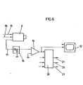
- FIG. 6 shows a schematic illustration of the circuit arrangement required for the evaluation of the signals received.
- a partial cutting machine 1 is shown within the route 2.
- the cutting arm of this partial cutting cutting machine is designated 3 and has at its end two rotating cutting heads 4 which are rotatably mounted about the axis 5 extending transversely to the axis of the cutting arm.
- a reference point 6 formed by an infrared transmitter is arranged on the cutting arm 3 near this axis 5.
- a thermal imager 8, which is aligned in a corresponding manner on the laser path guide beam 9, is arranged in a stationary manner on an expansion frame 7.
- the fixed receiver 8 determines the distance between the reference point 6 formed by an infrared transmitter on the cutting arm and the receiver 8.
- the Cartesian coordinates of the reference system of the receiver are indicated by x, y and z, and two angles are measured relative to this coordinate system, as is the case here is explained in Figs. 2 and 3.
- Fig. 2 the Cartesian reference system is shown with the origin at the measuring point of the thermal imager 8.
- the xy plane of this reference system is oriented in a simple manner parallel to the route guide beam 9.
- the reference point 6 of the cutting arm or cutting head is now in polar coordinates by the angle , and expressed the distance r.
- Two angles and the distance between the origin of the reference system of the thermal imager 8 and the reference point on the cutting head or cutting arm are thus measured.
- the outer contour of the cutting heads, designated by 10 in FIG. 1 is equally well known Entire be scanned by a thermal imager.
- the angles to be measured are shown in Fig. 3.
- the receiver 8 is in turn fixed on a removal frame 7 and oriented relative to the longitudinal axis of the line.
- the angle 1 is measured in relation to the xy plane of the reference system of the receiver and therefore appears in relation to the angle V in Fig. 3 reduced by 90 °.
- the angle is obtained in an analogous manner in the top view, not shown S starting from the x-axis of the reference system of the receiver.
- the distance a from the receiver 8 to the face 11 can be measured, since this distance is only slightly different from the distance r when the receiver 8 is at a greater distance from the reference point 6.
- the screen display shown in FIG. 5 can be obtained directly from the video signal of the thermal imaging camera obtained.
- the screen of the monitor 12 is designated 13 and shows the target profile 14 of the route to be covered. The images of the cutting heads 4 can be seen within this target profile 14, the traces of the rotating chisels being clearly shown as essentially vertical lines.
- FIG. 6 A circuit suitable for scanning the video signal of the thermal imaging camera is shown schematically in FIG. 6.
- the thermal imager is also designated 8 here, as is the receiver.
- the camera is fed signals for vertical and horizontal deflection via lines 15 and 16, respectively.
- the video signal arrives via line 17 and Differentiator 18 to a comparator 19 and can be fed directly to the monitor 12.
- this signal can also be fed to an image evaluation circuit 20.
- Separate control signals can be obtained via lines 21 for the three-space coordinates of the position of the cutting head.
Landscapes
- Engineering & Computer Science (AREA)
- Mining & Mineral Resources (AREA)
- Geology (AREA)
- Life Sciences & Earth Sciences (AREA)
- General Life Sciences & Earth Sciences (AREA)
- Geochemistry & Mineralogy (AREA)
- Mechanical Engineering (AREA)
- Environmental & Geological Engineering (AREA)
- Length Measuring Devices By Optical Means (AREA)
- Radiation Pyrometers (AREA)
- Laser Beam Processing (AREA)
- Machine Tool Sensing Apparatuses (AREA)
- Excavating Of Shafts Or Tunnels (AREA)
Applications Claiming Priority (2)
| Application Number | Priority Date | Filing Date | Title |
|---|---|---|---|
| AT3548/82 | 1982-09-23 | ||
| AT0354882A AT375153B (de) | 1982-09-23 | 1982-09-23 | Einrichtung zur erfassung der position des schraemkopfes einer vortriebs- oder gewinnungsmaschine |
Publications (3)
| Publication Number | Publication Date |
|---|---|
| EP0105867A2 true EP0105867A2 (fr) | 1984-04-18 |
| EP0105867A3 EP0105867A3 (en) | 1985-12-27 |
| EP0105867B1 EP0105867B1 (fr) | 1988-02-03 |
Family
ID=3552036
Family Applications (1)
| Application Number | Title | Priority Date | Filing Date |
|---|---|---|---|
| EP83890168A Expired EP0105867B1 (fr) | 1982-09-23 | 1983-09-22 | Equipement pour déterminer la position de la tête d'abattage d'une machine de creusement ou d'extraction |
Country Status (12)
| Country | Link |
|---|---|
| EP (1) | EP0105867B1 (fr) |
| JP (1) | JPS5980899A (fr) |
| AT (1) | AT375153B (fr) |
| AU (1) | AU563232B2 (fr) |
| CA (1) | CA1229675A (fr) |
| CS (1) | CS687583A2 (fr) |
| DE (1) | DE3375595D1 (fr) |
| HU (1) | HU191876B (fr) |
| IN (1) | IN159093B (fr) |
| PL (1) | PL142733B1 (fr) |
| RO (1) | RO89261A (fr) |
| ZA (1) | ZA836472B (fr) |
Cited By (8)
| Publication number | Priority date | Publication date | Assignee | Title |
|---|---|---|---|---|
| DE3806224A1 (de) * | 1988-02-26 | 1989-09-07 | Siemens Ag | Vorrichtung zur wegverfolgung eines bewegten objektes, insbesondere einer gewinnungsmaschine im bergbau |
| GB2260051A (en) * | 1991-09-13 | 1993-03-31 | Samsung Electronics Co Ltd | Tracking and ranging apparatus |
| EA014851B1 (ru) * | 2008-07-28 | 2011-02-28 | Айкхофф Бергбаутехник Гмбх | Способ управления режущей очистной машиной |
| CN102587911A (zh) * | 2012-03-08 | 2012-07-18 | 三一重型装备有限公司 | 掘进机的掘进控制系统和控制方法、掘进机 |
| US9733081B2 (en) | 2011-01-10 | 2017-08-15 | Leica Geosystems Ag | Geodesic measuring device comprising a thermographic camera |
| CN109538208A (zh) * | 2018-12-21 | 2019-03-29 | 冀中能源峰峰集团有限公司 | 一种掘进机截割头复合定位系统及方法 |
| CN111472841A (zh) * | 2020-03-05 | 2020-07-31 | 天地科技股份有限公司 | 一种综采工作面设备群位姿统一方法 |
| CN114718650A (zh) * | 2022-03-22 | 2022-07-08 | 中煤科工开采研究院有限公司 | 一种万向转换装置及安装方法 |
Families Citing this family (7)
| Publication number | Priority date | Publication date | Assignee | Title |
|---|---|---|---|---|
| CN103195433B (zh) * | 2013-03-20 | 2015-02-18 | 中国矿业大学(北京) | 一种大断面煤巷快速掘进的方法 |
| CN108655821B (zh) * | 2018-05-20 | 2019-11-29 | 李君毅 | 对中器和使用方法 |
| CN109356653B (zh) * | 2018-11-01 | 2023-10-24 | 云南昆钢电子信息科技有限公司 | 一种溜井深度测量装置及方法 |
| CN112963165B (zh) * | 2021-03-17 | 2022-01-04 | 大连理工大学 | 一种基于机器操作的全断面岩石掘进机刀具系统引导性定位接口的设计方法 |
| CN114658429B (zh) * | 2022-03-01 | 2023-05-23 | 河海大学 | 高温高压流体孔内循环冲击释能超前预裂破岩装置及方法 |
| CN115711157B (zh) * | 2022-11-14 | 2023-08-01 | 北京科技大学 | 基于采动磁场分布式监测的煤层突出危险区域识别方法 |
| CN118880682B (zh) * | 2024-06-05 | 2025-02-11 | 尤洛卡(广东)精准信息工程技术研究院有限公司 | 一种通过机器人安装矿用轨道的方法 |
Family Cites Families (6)
| Publication number | Priority date | Publication date | Assignee | Title |
|---|---|---|---|---|
| US3498673A (en) * | 1968-02-19 | 1970-03-03 | Lawrence Mfg Co | Machine guidance system and method |
| DE2458514C3 (de) * | 1974-12-11 | 1978-12-07 | Gebr. Eickhoff, Maschinenfabrik U. Eisengiesserei Mbh, 4630 Bochum | Vortriebsmaschine mit einem an einem allseitig schwenkbaren Tragarm gelagerten Lösewerkzeug und Verfahren zu ihrem Betrieb |
| DE2901598C2 (de) * | 1979-01-17 | 1986-03-20 | Gebr. Eickhoff Maschinenfabrik U. Eisengiesserei Mbh, 4630 Bochum | Vorrichtung zur Kontrolle der Lage einer Teilschnittvortriebsmaschine |
| DE2944305C2 (de) * | 1979-11-02 | 1983-01-27 | Hochtief Ag Vorm. Gebr. Helfmann, 4300 Essen | Steuerleitgerät für eine Tunnelvortriebsmaschine |
| DE3016592A1 (de) * | 1980-04-30 | 1981-11-05 | Gewerkschaft Eisenhütte Westfalia, 4670 Lünen | Verfahren und einrichtung zum profilgenauen schneiden des vortriebsquerschnitts beim vortrieb unterirdischer bauwerke |
| DE3120010A1 (de) * | 1981-05-20 | 1982-12-09 | Ed. Züblin AG, 7000 Stuttgart | Verfahren zur positionsbestimmung eines vorgepressten hohlprofilstrangs und vorrichtung zur durchfuehrung des verfahrens |
-
1982
- 1982-09-23 AT AT0354882A patent/AT375153B/de not_active IP Right Cessation
-
1983
- 1983-08-24 IN IN1035/CAL/83A patent/IN159093B/en unknown
- 1983-08-25 AU AU18428/83A patent/AU563232B2/en not_active Ceased
- 1983-08-25 PL PL1983243526A patent/PL142733B1/pl unknown
- 1983-08-31 ZA ZA836472A patent/ZA836472B/xx unknown
- 1983-09-02 HU HU833073A patent/HU191876B/hu unknown
- 1983-09-08 CA CA000436256A patent/CA1229675A/fr not_active Expired
- 1983-09-12 RO RO83112039A patent/RO89261A/fr unknown
- 1983-09-21 CS CS836875A patent/CS687583A2/cs unknown
- 1983-09-22 JP JP58174453A patent/JPS5980899A/ja active Pending
- 1983-09-22 EP EP83890168A patent/EP0105867B1/fr not_active Expired
- 1983-09-22 DE DE8383890168T patent/DE3375595D1/de not_active Expired
Cited By (12)
| Publication number | Priority date | Publication date | Assignee | Title |
|---|---|---|---|---|
| DE3806224A1 (de) * | 1988-02-26 | 1989-09-07 | Siemens Ag | Vorrichtung zur wegverfolgung eines bewegten objektes, insbesondere einer gewinnungsmaschine im bergbau |
| GB2260051A (en) * | 1991-09-13 | 1993-03-31 | Samsung Electronics Co Ltd | Tracking and ranging apparatus |
| GB2260051B (en) * | 1991-09-13 | 1996-01-10 | Samsung Electronics Co Ltd | Object tracking apparatus and method |
| EA014851B1 (ru) * | 2008-07-28 | 2011-02-28 | Айкхофф Бергбаутехник Гмбх | Способ управления режущей очистной машиной |
| US8469455B2 (en) | 2008-07-28 | 2013-06-25 | Eickhoff Bergbautechnik Gmbh | Method for controlling a cutting extraction machine |
| US9733081B2 (en) | 2011-01-10 | 2017-08-15 | Leica Geosystems Ag | Geodesic measuring device comprising a thermographic camera |
| CN102587911A (zh) * | 2012-03-08 | 2012-07-18 | 三一重型装备有限公司 | 掘进机的掘进控制系统和控制方法、掘进机 |
| CN102587911B (zh) * | 2012-03-08 | 2014-04-23 | 三一重型装备有限公司 | 掘进机的掘进控制系统和控制方法、掘进机 |
| CN109538208A (zh) * | 2018-12-21 | 2019-03-29 | 冀中能源峰峰集团有限公司 | 一种掘进机截割头复合定位系统及方法 |
| CN111472841A (zh) * | 2020-03-05 | 2020-07-31 | 天地科技股份有限公司 | 一种综采工作面设备群位姿统一方法 |
| CN111472841B (zh) * | 2020-03-05 | 2021-11-05 | 天地科技股份有限公司 | 一种综采工作面设备群位姿统一方法 |
| CN114718650A (zh) * | 2022-03-22 | 2022-07-08 | 中煤科工开采研究院有限公司 | 一种万向转换装置及安装方法 |
Also Published As
| Publication number | Publication date |
|---|---|
| AT375153B (de) | 1984-07-10 |
| AU563232B2 (en) | 1987-07-02 |
| JPS5980899A (ja) | 1984-05-10 |
| IN159093B (fr) | 1987-03-21 |
| EP0105867A3 (en) | 1985-12-27 |
| CS687583A2 (en) | 1988-09-16 |
| CA1229675A (fr) | 1987-11-24 |
| HU191876B (en) | 1987-04-28 |
| EP0105867B1 (fr) | 1988-02-03 |
| ZA836472B (en) | 1984-04-25 |
| ATA354882A (de) | 1983-11-15 |
| RO89261A (fr) | 1986-03-15 |
| DE3375595D1 (en) | 1988-03-10 |
| PL243526A1 (en) | 1984-04-09 |
| PL142733B1 (en) | 1987-11-30 |
| AU1842883A (en) | 1984-03-29 |
Similar Documents
| Publication | Publication Date | Title |
|---|---|---|
| EP0105867B1 (fr) | Equipement pour déterminer la position de la tête d'abattage d'une machine de creusement ou d'extraction | |
| DE3322683C2 (de) | Vorrichtung zum Ernten von Früchten mit einem fotoelektrischen Fruchtlagedetektor | |
| EP2005112B1 (fr) | Dispositif et procédé d'acquisition tridimensionnelle d'une zone d'espace | |
| EP3054264B1 (fr) | Dispositif et procédé de détermination d'écart de positions nominales de deux corps | |
| DE69402724T2 (de) | Führungsanlage | |
| EP1549909B1 (fr) | Dispositif d'affichage et de commande electronique destine a un appareil de mesure | |
| DE68919979T2 (de) | Überwachungsradar. | |
| DE3426505C2 (fr) | ||
| DE69005106T2 (de) | Anordnung zum erstellen oder bestimmen der ortung eines messpunktes. | |
| DE102007044605B4 (de) | Vermessungsgerät | |
| DE10000491A1 (de) | Verfahren und Messeinrichtung zum Vermessen eines Rotationswerkzeuges | |
| DE3007893C2 (de) | Wärmebildgerät | |
| EP2801789A1 (fr) | Dispositif de détermination de la position d'éléments mécaniques | |
| EP2801788B1 (fr) | Dispositif et méthode de détermination de l'alignement d'éléments mécaniques | |
| DE69825525T2 (de) | Vorrichtung zur Erstellung eines Bildes sowie Verfahren und Vorrichtung zur Entfernungsmessung | |
| DE3417666A1 (de) | Bilderzeuger | |
| EP0481278A1 (fr) | Procédé et installation de mesure pour localisation de points dans l'espace | |
| EP0403908A2 (fr) | Procédé et dispositif pour mesurer les contours d'un objet | |
| DE102016200877A1 (de) | System zum Messen einer dreidimensionalen Position | |
| DE19543299A1 (de) | Verfahren und Vorrichtung zum Vermessen von Gegenständen | |
| DE102010020537A1 (de) | Wasserdetektor | |
| DE102014202977A1 (de) | Bestimmung von Koordinaten eines Werkstücks unter Verwendung eines Koordinatenmessgeräts | |
| EP0068431A2 (fr) | Dispositif pour visualiser les extrémités de produits laminés | |
| WO2019233701A1 (fr) | Procédé et dispositif pour la mesure de vibrations d'un objet par l'utilisation d'un drone | |
| DE102017100885B4 (de) | Verfahren und vorrichtung zum erzeugen und projizieren eines 3d-thermogramms samt daten zu den aufnahmebedingungen |
Legal Events
| Date | Code | Title | Description |
|---|---|---|---|
| PUAI | Public reference made under article 153(3) epc to a published international application that has entered the european phase |
Free format text: ORIGINAL CODE: 0009012 |
|
| AK | Designated contracting states |
Designated state(s): CH DE FR GB LI SE |
|
| PUAL | Search report despatched |
Free format text: ORIGINAL CODE: 0009013 |
|
| AK | Designated contracting states |
Designated state(s): CH DE FR GB LI SE |
|
| 17P | Request for examination filed |
Effective date: 19860120 |
|
| 17Q | First examination report despatched |
Effective date: 19870604 |
|
| GRAA | (expected) grant |
Free format text: ORIGINAL CODE: 0009210 |
|
| AK | Designated contracting states |
Kind code of ref document: B1 Designated state(s): CH DE FR GB LI SE |
|
| GBT | Gb: translation of ep patent filed (gb section 77(6)(a)/1977) | ||
| REF | Corresponds to: |
Ref document number: 3375595 Country of ref document: DE Date of ref document: 19880310 |
|
| ET | Fr: translation filed | ||
| PG25 | Lapsed in a contracting state [announced via postgrant information from national office to epo] |
Ref country code: GB Effective date: 19880922 |
|
| PG25 | Lapsed in a contracting state [announced via postgrant information from national office to epo] |
Ref country code: SE Effective date: 19880923 |
|
| PG25 | Lapsed in a contracting state [announced via postgrant information from national office to epo] |
Ref country code: LI Effective date: 19880930 Ref country code: CH Effective date: 19880930 |
|
| PLBE | No opposition filed within time limit |
Free format text: ORIGINAL CODE: 0009261 |
|
| STAA | Information on the status of an ep patent application or granted ep patent |
Free format text: STATUS: NO OPPOSITION FILED WITHIN TIME LIMIT |
|
| 26N | No opposition filed | ||
| PG25 | Lapsed in a contracting state [announced via postgrant information from national office to epo] |
Ref country code: FR Free format text: LAPSE BECAUSE OF NON-PAYMENT OF DUE FEES Effective date: 19890531 |
|
| REG | Reference to a national code |
Ref country code: CH Ref legal event code: PL |
|
| GBPC | Gb: european patent ceased through non-payment of renewal fee | ||
| PG25 | Lapsed in a contracting state [announced via postgrant information from national office to epo] |
Ref country code: DE Effective date: 19890601 |
|
| REG | Reference to a national code |
Ref country code: FR Ref legal event code: ST |
|
| EUG | Se: european patent has lapsed |
Ref document number: 83890168.4 Effective date: 19890712 |