EP0106034A1 - Débitmètre pour liquides et gaz - Google Patents
Débitmètre pour liquides et gaz Download PDFInfo
- Publication number
- EP0106034A1 EP0106034A1 EP83107245A EP83107245A EP0106034A1 EP 0106034 A1 EP0106034 A1 EP 0106034A1 EP 83107245 A EP83107245 A EP 83107245A EP 83107245 A EP83107245 A EP 83107245A EP 0106034 A1 EP0106034 A1 EP 0106034A1
- Authority
- EP
- European Patent Office
- Prior art keywords
- housing
- rails
- fastening
- rail
- display instrument
- Prior art date
- Legal status (The legal status is an assumption and is not a legal conclusion. Google has not performed a legal analysis and makes no representation as to the accuracy of the status listed.)
- Granted
Links
Images


Classifications
-
- G—PHYSICS
- G01—MEASURING; TESTING
- G01F—MEASURING VOLUME, VOLUME FLOW, MASS FLOW OR LIQUID LEVEL; METERING BY VOLUME
- G01F1/00—Measuring the volume flow or mass flow of fluid or fluent solid material wherein the fluid passes through a meter in a continuous flow
- G01F1/05—Measuring the volume flow or mass flow of fluid or fluent solid material wherein the fluid passes through a meter in a continuous flow by using mechanical effects
- G01F1/20—Measuring the volume flow or mass flow of fluid or fluent solid material wherein the fluid passes through a meter in a continuous flow by using mechanical effects by detection of dynamic effects of the flow
- G01F1/22—Measuring the volume flow or mass flow of fluid or fluent solid material wherein the fluid passes through a meter in a continuous flow by using mechanical effects by detection of dynamic effects of the flow by variable-area meters, e.g. rotameters
- G01F1/24—Measuring the volume flow or mass flow of fluid or fluent solid material wherein the fluid passes through a meter in a continuous flow by using mechanical effects by detection of dynamic effects of the flow by variable-area meters, e.g. rotameters with magnetic or electric coupling to the indicating device
-
- G—PHYSICS
- G01—MEASURING; TESTING
- G01F—MEASURING VOLUME, VOLUME FLOW, MASS FLOW OR LIQUID LEVEL; METERING BY VOLUME
- G01F15/00—Details of, or accessories for, apparatus of groups G01F1/00 - G01F13/00 insofar as such details or appliances are not adapted to particular types of such apparatus
- G01F15/14—Casings, e.g. of special material
Definitions
- the invention relates to a device for flow measurement of liquids or gases according to the float principle, in particular the design of the housing, an attached display instrument and a switch which is actuated by the float at a desired flow rate to be determined.
- the measuring section can consist of transparent material, so that an optical control of the position is possible
- the float can contain a magnet which, in a certain position, actuates a switch located on the side next to the measuring section and thus triggers a signal.
- the float was arranged with some play axially movable in a cylindrical cage designed in a certain way. The cage is designed so that a narrower cross-section between the float and the cage wall or housing wall of the measuring section is initially available for the flow.
- the cross section increases so that the stroke length is reduced. This enables the overall length of the measuring device to be shortened.
- the object of the present invention is to provide a structural design of a device for flow measurement, which consists of a measuring device with a display instrument and a contact switch and whose individual parts can be assembled in a simple manner according to the modular principle and can be adapted to different measuring ranges and measuring problems without great effort are.
- a device for measuring the flow of gases and liquids according to the float principle with a float arranged in the housing and a display instrument attached to the outside of the housing and a sliding contact switch.
- the invention is characterized in that the housing (1) of the flow meter made of metal or plastic has a support surface for mounting rails (2) on the back, on the rear side of the housing two L-shaped mounting rails (2) are provided in a cavity (10) between the rails (2) one T-shaped rail (15), which is attached to a base plate (12) of a switch part (11), is inserted and the housing (19) of the display instrument (4) is arranged on the side of the housing (1) of the flow meter and on this Clamp or fastened with screws.
- the switch part is attached to the rear of the flow meter housing so as to be displaceable in the longitudinal direction in order to be able to adjust the switching point to the desired flow rate.
- the switch part is fixed by means of the fastening rails on the rear of the housing in such a position by a locking screw that the protective gas contact switch arranged in the switch part is triggered by an axially magnetized magnet arranged in the measuring body in accordance with the lifting height of the measuring body.
- the lifting height of the measuring body in the housing can be determined by design measures, i.e.
- the housing of the flow meter preferably has a square or rectangular cross section. It can be made of metal, too. be made of plastic.
- the L-shaped mounting rails are each attached to the bearing surface of the rear wall of the housing by means of two countersunk screws so that the longer legs do not lie against the housing wall, face each other and their ends do not touch, so that between the housing wall, the inside of the Rails creates a cavity that is open between the facing leg ends.
- the leg of one or both fastening rails resting against the wall of the housing (1) has a longitudinal groove, so that a gap is formed between the housing wall and the fastening rail.
- the longitudinal groove on the legs ends at a distance of 10 to 20 mm from the leg ends and in the stronger leg ends there are holes for receiving the fastening screws for the rails.
- the bearing surface of the wall of the housing on the back of the flow meter has 4 threaded holes, which are arranged in pairs at the top and bottom near the ends, in order to be able to fasten the fastening rails to the housing by means of countersunk screws.
- the switch part consists of a rectangular base plate on which on one side a longitudinal T-rail or web and on the opposite side an insulating plate with the connection contacts for the protective gas contact switches are attached.
- the crossbar of the T-shaped rail is not in contact with the base plate, so that the T-profile can be inserted into the cavity (10) formed from the L-shaped fastening rails on the rear of the housing.
- a longitudinal recess is milled into which a protective gas contact switch, a so-called reed contact, is cast, the connections of which are connected in electrical connection with the contacts in the insulating plate on the other side of the switch part are.
- the simply constructed switch part and the connection to the flow meter via the fastening rails make it possible to use the same switch part for different flow meters, the length of the fastening rails possibly having to be adapted to different lifting heights.
- a length of 100-130 mm of the mounting rails is sufficient, so that a reduced number of individual parts is possible according to the modular principle, especially after a rail length is sufficient due to the symmetrical arrangement of the mounting rails and these are only rotated with respect to each other in each of the legs facing away from the housing wall can be screwed facing each other.
- the distance between the ends of the legs facing each other is preferably 10 - 12 mm and the length of the other leg 3 - 8 mm, so that there is a cavity depth for receiving the crossbar of the T-profile of the switch part of 3 - 8, preferably 5 mm.
- the rails are attached with countersunk screws that reach through the rails so that the base plate of the switch part rests on the outside of the rails.
- a display instrument is attached to the side of the housing. This can be done using screws. However, clamping by means of fastening tabs is preferred.
- the housing of the display instrument has in this case on the side facing the flow meter two flat fastening tabs which are inserted into the gap between the housing wall and the fastening rail and are slightly thicker than the gap, so that when the fastening rail screws are tightened, the tabs in the gap are clamped and so a fixed, but selectable in height on the flow meter fixed position of the display instrument is available.
- the housing of the display instrument consists of a frame-shaped central part made of transparent material, preferably plastic, such as polycarbonate or acrylic glass or the like, and two side plates made of metal.
- the flat fastening tab is formed on one of the side plates by cutting a rectangular or square section that is bent out on one side surface.
- the gap between Housing wall and mounting rail is designed to clamp slightly narrower than the thickness of the metal plates of the side walls of the housing of the display instrument.
- the frame-shaped central part of the housing has a step on each of the two lateral edges, into which the side plates are inserted.
- a pointer frame with the pointer is fastened between the side plates within the housing by means of screws penetrating through holes in the side plates.
- the pointer frame has a customary design, the pointer axis being arranged between two base plates which are spaced apart by sleeves.
- the pointer has a ferritic part or is designed as a whole ferritic pointer. Its tip is bent on the front side inside the housing and laterally comprises a scale arranged at a distance from the front side. There is a counterweight at the rear end of the pointer.
- the ferritic pointer or the corresponding section is magnetically coupled to the axially magnetized magnet within the measuring body, so that the pointer is raised in the same way in accordance with the flow-related stroke of the measuring body and the bent end enables a reading of the scale value.
- the end face of the housing is curved and at a distance from it an appropriately curved scale is inserted into slots in the interior.
- the possible longitudinal displacement of the fastening nipples within the gap allows the display instrument to be arranged at different heights on the flow meter, so that in this way it is additionally possible to adapt to different measuring ranges and positions of the measuring body within the flow meter.
- the display instrument which is designed in a structurally simple manner and can be attached, can be built after construction box principle can be used for different flow meters, the structural design and design of the attachment making it possible to adapt that the position of the pointer tip corresponds to the position of the measuring body within the flow meter.
- the switch part (11) shown in FIG. 3 in section III - III according to FIG. 4 consists of a base plate (12) onto which an insulating plate (13) with the mutually insulated connecting plug contacts (14) is screwed on one side.
- On the other side of the base plate (12) is a T-shaped footbridge or rail fastened with screws.
- the crossbar of the T is of such a size that it fits into the cavity 10 between the fastening rails 2 and the straight piece of the T fastened to the base plate 12 is so wide that it has the space between the mutually facing legs of the rail 2 fills little play, so that the T-shaped rail 15 can be inserted into the cavity 10.
- a protective gas contact switch 16 a so-called reed contact, is cast in a longitudinal groove.
- the ends of the switch 16 are electrically conductively connected to the connection contacts 14 via insulated wires.
- the longitudinal section of the switch part 12 from the side shows the arrangement of the protective gas contact switch in the groove of the crossbar of the T-shaped web 15 and the wire connection to the connection contacts 14.
- the switch part 11 has a continuous threaded bore 17 in order to a countersunk screw that presses in the fixed state against the wall of the housing 1 to fix the switch part 11 in its position on the wall of the housing 1.
- the contact of the protective gas contact switch 6 is closed as soon as the measuring body of the flow meter is located inside the housing 1 at the same height as the contact ends.
- the make contact is generated by axially magnetized magnets arranged in the measuring body.
- the position of the switch part 11 on the housing wall is selected and determined such that the desired switching point is given in accordance with the lifting height of the measuring body.
- the structural design of the flow meter within the housing 1 is such that a bistable switching behavior is given and the stroke of the measuring body is limited so that when the desired setpoint is exceeded, the influence of the magnet on the protective gas contact switch 16 remains and the switch only opens when the stroke height of the measuring body, which corresponds to the setpoint value, is undershot by falling below the flow rate.
- the longitudinal section of the switch part 11 is shown in Figure 4.
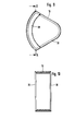
- FIG. 5 shows how the display instrument 4 is mounted laterally on the housing 1 of the flow meter by means of two fastening tabs 18 which engage in the gap 9 between the housing 1 and the fastening rail 2 on the rear.
- the display instrument has a housing 19 (frame-shaped middle part) with a transparent end face and is preferably made of plastic (polycarbonate or acrylic glass or the like).
- a scale is arranged on the inside such that it is encompassed by the bent pointer tip 27 of the pointer 21 and the position of the pointer can be read from the scale.
- Figure 6 the object of Figure 5, rotated by 90 °, is shown from the side.
- the mounting rails 2 are fastened with the screws 8.
- the display instrument 4 is clamped in the gap 9 with the fastening nipples 18 starting from the side plate 22 of the housing 19 and which cannot be seen in this figure.
- the other side of the housing of the display instrument 4 is designed as a continuous side plate 23 with 2 holes. Screws 25 can be inserted through the bores and screwed into the thread of the pointer frame 24 for fastening the second side plate 23.
- the other side plate 22 with the pointer frame 24 fastened thereon is reproduced give.
- the fastening tabs 18 are formed by cutting, pressing out and bending a rectangular or square part out of the metal side plate 22.
- the pointer frame 24 is fastened to the side plate 22 with screws 26.
- the pointer 21 has a tip 27 bent around the scale, a ferritic section 28 or is designed as a whole ferritic and a counterweight 29 at the other end.
- FIGS. 9 and 10 show the frame-shaped middle piece of the housing 19 of the display instrument from the side with the side cover plate removed and from the front without the side plates 22, 23.
- the edge is provided with a step 30 on the inside in each case to accommodate the side plates 22, 23.
- the area around the holes in the side plates for the fastening screws of the pointer frame is pressed slightly towards the inside of the housing so that the countersunk head of the fastening screws 25, 26 can be received in the recess.
- the scale 20 is inserted into slots on the inside of the frame-shaped housing part and bent in accordance with the curved end face of the frame-shaped middle part.
- the scale has a distance between the one side wall 23 of the housing 19 in order to enable the pointer to pass through and the scale 20 to be grasped by the bent pointer tip 27.
- the display instrument 4 is fastened to the housing 1 of the flow meter in such a position that the pointer 21 raised and moved by the magnet of the measuring body by acting on the ferritic pointer or the ferritic pointer part 28 has the flow rate corresponding to the position of the measuring body displays. Due to the easily replaceable scale, the longitudinal displaceability of the display instrument 4 on the housing 1 and, if necessary, changing the measuring body, the device can be easily adapted to different measuring ranges, the individual parts of the device can be easily assembled according to the modular system and only a few parts need to be replaced for different measuring problems .
- the display instrument is basically the same for different display cases, so that manufacturing and warehousing are significantly simplified.
- the constructive design according to the invention enables a considerable reduction in the size of the display instrument and the switch part 11, so that the space requirement for the entire device, including the flow meter, is considerably reduced.
Landscapes
- Physics & Mathematics (AREA)
- Fluid Mechanics (AREA)
- General Physics & Mathematics (AREA)
- Measuring Volume Flow (AREA)
Applications Claiming Priority (2)
| Application Number | Priority Date | Filing Date | Title |
|---|---|---|---|
| DE19828226199U DE8226199U1 (de) | 1982-09-17 | 1982-09-17 | Vorrichtung zur durchflussmessung von fluessigkeiten und gasstroemen |
| DE8226199U | 1982-09-17 |
Publications (2)
| Publication Number | Publication Date |
|---|---|
| EP0106034A1 true EP0106034A1 (fr) | 1984-04-25 |
| EP0106034B1 EP0106034B1 (fr) | 1987-03-18 |
Family
ID=6743764
Family Applications (1)
| Application Number | Title | Priority Date | Filing Date |
|---|---|---|---|
| EP83107245A Expired EP0106034B1 (fr) | 1982-09-17 | 1983-07-23 | Débitmètre pour liquides et gaz |
Country Status (4)
| Country | Link |
|---|---|
| US (1) | US4567777A (fr) |
| EP (1) | EP0106034B1 (fr) |
| DE (2) | DE8226199U1 (fr) |
| ES (1) | ES283041Y (fr) |
Cited By (1)
| Publication number | Priority date | Publication date | Assignee | Title |
|---|---|---|---|---|
| CN104299387A (zh) * | 2014-10-29 | 2015-01-21 | 成都众山科技有限公司 | 能够避免短路的无线变送器 |
Families Citing this family (4)
| Publication number | Priority date | Publication date | Assignee | Title |
|---|---|---|---|---|
| US4877651A (en) * | 1988-05-31 | 1989-10-31 | Olin Corporation | Process for thermally depositing silicon nitride and silicon dioxide films onto a substrate |
| DE19650361C2 (de) * | 1996-12-06 | 1999-05-20 | Krohne Messtechnik Kg | Schwebekörper-Durchflußmesser |
| DE29905655U1 (de) * | 1999-03-26 | 1999-08-05 | Reich KG Regel- und Sicherheitstechnik, 35713 Eschenburg | Meßvorrichtung zur Messung von Durchflußmenge und Temperatur eines fließfähigen Mediums |
| DE102011113869A1 (de) * | 2011-09-22 | 2013-03-28 | Krohne Messtechnik Gmbh | Schwebekörperdurchflussmessgerät mit Grenzwertschalter |
Citations (4)
| Publication number | Priority date | Publication date | Assignee | Title |
|---|---|---|---|---|
| DE1272010B (de) * | 1964-07-24 | 1968-07-04 | Erika Tiefenbach | Vorrichtung zur Durchflussmessung |
| FR2115225A1 (fr) * | 1970-11-19 | 1972-07-07 | Bp Chem Int Ltd | |
| DE2255327A1 (de) * | 1972-11-11 | 1974-05-22 | Gustav Dr Ing Schenk | Durchflussmesser |
| DE3027763A1 (de) * | 1979-07-23 | 1981-02-19 | Emerson Electric Co | Schwebekoerper-durchflussmesser |
Family Cites Families (5)
| Publication number | Priority date | Publication date | Assignee | Title |
|---|---|---|---|---|
| US2628297A (en) * | 1946-09-20 | 1953-02-10 | Carl T Grauer | Shielded switch assembly |
| DE939539C (de) * | 1953-03-03 | 1956-02-23 | Norma | Messgeraet zur Bestimmung der Bremsverzoegerung bzw. der Brems-beschleunigung sowie der Zentripetalbeschleunigung von Fahrzeugen und gegebenenfalls der Fahrbahnsteigung |
| US3137165A (en) * | 1958-12-03 | 1964-06-16 | Schutte & Koerting Co | Pneumatic transmitters |
| US3398249A (en) * | 1967-02-13 | 1968-08-20 | Square D Co | Molded case circuit breaker and mounting means therefor |
| US3766779A (en) * | 1971-12-29 | 1973-10-23 | Orange Res Inc | Hydraulic responsive device |
-
1982
- 1982-09-17 DE DE19828226199U patent/DE8226199U1/de not_active Expired
-
1983
- 1983-07-01 US US06/510,220 patent/US4567777A/en not_active Expired - Lifetime
- 1983-07-23 EP EP83107245A patent/EP0106034B1/fr not_active Expired
- 1983-07-23 DE DE8383107245T patent/DE3370375D1/de not_active Expired
- 1983-09-16 ES ES1983283041U patent/ES283041Y/es not_active Expired
Patent Citations (4)
| Publication number | Priority date | Publication date | Assignee | Title |
|---|---|---|---|---|
| DE1272010B (de) * | 1964-07-24 | 1968-07-04 | Erika Tiefenbach | Vorrichtung zur Durchflussmessung |
| FR2115225A1 (fr) * | 1970-11-19 | 1972-07-07 | Bp Chem Int Ltd | |
| DE2255327A1 (de) * | 1972-11-11 | 1974-05-22 | Gustav Dr Ing Schenk | Durchflussmesser |
| DE3027763A1 (de) * | 1979-07-23 | 1981-02-19 | Emerson Electric Co | Schwebekoerper-durchflussmesser |
Cited By (1)
| Publication number | Priority date | Publication date | Assignee | Title |
|---|---|---|---|---|
| CN104299387A (zh) * | 2014-10-29 | 2015-01-21 | 成都众山科技有限公司 | 能够避免短路的无线变送器 |
Also Published As
| Publication number | Publication date |
|---|---|
| ES283041U (es) | 1985-07-01 |
| EP0106034B1 (fr) | 1987-03-18 |
| DE8226199U1 (de) | 1982-12-16 |
| US4567777A (en) | 1986-02-04 |
| DE3370375D1 (en) | 1987-04-23 |
| ES283041Y (es) | 1986-04-01 |
Similar Documents
| Publication | Publication Date | Title |
|---|---|---|
| DE3331305C2 (fr) | ||
| DE602005003777T2 (de) | Oberflächenmontierter integrierter Stromsensor | |
| DE19650361C2 (de) | Schwebekörper-Durchflußmesser | |
| DE102017104349A1 (de) | Wägezelle für eine Waage | |
| EP0292636A1 (fr) | Convertisseur de courant pour mesurer un courant passant dans un conducteur électrique | |
| DE7739839U1 (de) | Potentiometer | |
| EP0106034A1 (fr) | Débitmètre pour liquides et gaz | |
| EP0188789A2 (fr) | Capteur de champ magnétique | |
| DE102017115155B4 (de) | Magnetisch-induktives Durchflussmessgerät | |
| EP0101532B1 (fr) | Débitmètre avec interrupteur de contact de fin de course, libre de potentiel | |
| DE3632739A1 (de) | Magnetisch betaetigbares potentiometer | |
| DE1928485A1 (de) | Vorrichtung zum Anschluss und zur Klemmung des Innenleiters und des Aussenleiters eines Koaxialkabels | |
| DE2753156C3 (de) | SchwebekörperdurchfluBmesser mit einem axial durchströmten zylindrischen Gehäuse | |
| DE3244718C2 (de) | Vorrichtung zum Befestigen von elektrischen Bauteilen im Anschlußkopf von elektrischen Thermometern | |
| DE2036695A1 (de) | Coulombmetereinrichtung zur elektrochemischen Messung des Zeitablaufs | |
| DE2652672A1 (de) | Gehaeuse fuer geraete der elektrischen nachrichten- und messtechnik | |
| DE68906873T2 (de) | Vorrichtung zum messen des niveaus einer in einem sehr hohen behaelter enthaltenen fluessigkeit. | |
| DE9206255U1 (de) | Meßfühler | |
| DE3131389A1 (de) | "elektrischer vibrationsfuehler" | |
| DE4215258C2 (de) | Sensor | |
| DE3712948A1 (de) | Elektrode fuer einen magnetisch-induktiven durchflussmesser | |
| DE2710261A1 (de) | Klemmstueck fuer die anbringung von elektrischen schaltkaesten an halterungsschienen | |
| CH664828A5 (de) | Magnetniveaustandsanzeiger. | |
| DE3411620C2 (fr) | ||
| DE2631181A1 (de) | Fluid-messvorrichtung |
Legal Events
| Date | Code | Title | Description |
|---|---|---|---|
| PUAI | Public reference made under article 153(3) epc to a published international application that has entered the european phase |
Free format text: ORIGINAL CODE: 0009012 |
|
| AK | Designated contracting states |
Designated state(s): DE GB IT NL |
|
| 17P | Request for examination filed |
Effective date: 19841024 |
|
| GRAA | (expected) grant |
Free format text: ORIGINAL CODE: 0009210 |
|
| AK | Designated contracting states |
Kind code of ref document: B1 Designated state(s): DE GB IT NL |
|
| REF | Corresponds to: |
Ref document number: 3370375 Country of ref document: DE Date of ref document: 19870423 |
|
| ITF | It: translation for a ep patent filed | ||
| PLBI | Opposition filed |
Free format text: ORIGINAL CODE: 0009260 |
|
| 26 | Opposition filed |
Opponent name: DR. F. K. FESSEL GMBH Effective date: 19871216 |
|
| NLR1 | Nl: opposition has been filed with the epo |
Opponent name: DR.F.K. FESSEL GMBH |
|
| PLBN | Opposition rejected |
Free format text: ORIGINAL CODE: 0009273 |
|
| STAA | Information on the status of an ep patent application or granted ep patent |
Free format text: STATUS: OPPOSITION REJECTED |
|
| 27O | Opposition rejected |
Effective date: 19890925 |
|
| NLR2 | Nl: decision of opposition | ||
| ITTA | It: last paid annual fee | ||
| REG | Reference to a national code |
Ref country code: GB Ref legal event code: IF02 |
|
| PGFP | Annual fee paid to national office [announced via postgrant information from national office to epo] |
Ref country code: GB Payment date: 20020701 Year of fee payment: 20 |
|
| PGFP | Annual fee paid to national office [announced via postgrant information from national office to epo] |
Ref country code: NL Payment date: 20020717 Year of fee payment: 20 |
|
| PGFP | Annual fee paid to national office [announced via postgrant information from national office to epo] |
Ref country code: DE Payment date: 20020925 Year of fee payment: 20 |
|
| PG25 | Lapsed in a contracting state [announced via postgrant information from national office to epo] |
Ref country code: GB Free format text: LAPSE BECAUSE OF EXPIRATION OF PROTECTION Effective date: 20030722 |
|
| PG25 | Lapsed in a contracting state [announced via postgrant information from national office to epo] |
Ref country code: NL Free format text: LAPSE BECAUSE OF EXPIRATION OF PROTECTION Effective date: 20030723 |
|
| REG | Reference to a national code |
Ref country code: GB Ref legal event code: PE20 |
|
| NLV7 | Nl: ceased due to reaching the maximum lifetime of a patent |
Effective date: 20030723 |