EP0106191A1 - Système de multiprocesseur pour l'installation d'un avertisseur de danger - Google Patents
Système de multiprocesseur pour l'installation d'un avertisseur de danger Download PDFInfo
- Publication number
- EP0106191A1 EP0106191A1 EP83109277A EP83109277A EP0106191A1 EP 0106191 A1 EP0106191 A1 EP 0106191A1 EP 83109277 A EP83109277 A EP 83109277A EP 83109277 A EP83109277 A EP 83109277A EP 0106191 A1 EP0106191 A1 EP 0106191A1
- Authority
- EP
- European Patent Office
- Prior art keywords
- module
- modules
- ala
- data
- central computer
- Prior art date
- Legal status (The legal status is an assumption and is not a legal conclusion. Google has not performed a legal analysis and makes no representation as to the accuracy of the status listed.)
- Granted
Links
Images

Classifications
-
- G—PHYSICS
- G08—SIGNALLING
- G08B—SIGNALLING SYSTEMS, e.g. PERSONAL CALLING SYSTEMS; ORDER TELEGRAPHS; ALARM SYSTEMS
- G08B26/00—Alarm systems in which substations are interrogated in succession by a central station
- G08B26/008—Alarm systems in which substations are interrogated in succession by a central station central annunciator means of the sensed conditions, e.g. displaying or registering
Definitions
- the invention relates to a multiprocessor system for hazard detection systems according to the preamble of claim 1.
- a central data processing system In today's security alarm systems, a central data processing system is often used to process the large amount of information, but also to reduce the number of components. This is associated with the particular risk that one of the central modules could become inoperable, which would result in the failure of the entire alarm system. If, for example, the central computer or essential functions fail, the entire system is system inoperable. To ensure the reliability of such systems, special monitoring modules were provided in the central computer of the data processing system. This problem was also solved in software by separate test routines of the central computer, which then initiate an emergency operation if necessary.
- DE-OS 28 17 121 describes a hazard alarm system with a plurality of detectors which can be connected to a central unit via alarm lines.
- This system consists of a number of individual system blocks with connection devices for one or more detectors or for one or more subordinate system blocks, which have a programmed control system for querying and evaluating the incoming detector signals as well as connections for display, operating and registration elements.
- the system blocks are interconnected with lines, e.g. with a two-wire line, connected in such a way that one of the system blocks can be used as a control center and the other system blocks are subordinate to this control center in one or more hierarchical levels.
- subordinate system blocks can at least partially take over their assigned functions independently, so that they can maintain emergency operation and still display danger messages.
- Other measures such as send a message to a main detector or activate control lines, e.g. to It is not intended to open smoke flaps or close fire compartment doors.
- the object of the invention is to provide a multiprocessor system for hazard alarm systems with a large number of To create functional modules.
- the aim is to increase reliability and reduce the risk of system failure, particularly if the central computer fails, so that the essential functions are maintained in the case of a distributed system intelligence and no danger message can be lost. Not only is emergency operation to be taken over, but the most important tasks of a hazard alarm system can also be carried out.
- a system should be adapted to the respective application requirements in a simple manner and should have the ease of use of large systems.
- the modular hazard alarm system has a large number of modules, so-called function modules. It has different types of modules for different functions, modules of the same type for similar functions and a central computer module. In addition to the central computer module, various types of modules are, for example, an operating and display module, a block lock connection module and an input and output module for serial 'data input and output. Modules of the same structure are autonomous line interface modules for the respective connection of signaling and control lines. All modules are connected to a microprocessor-controlled data bus for the data transmission of the individual modules to each other and to the central computer module.
- each module is connected to a hardwired signal bus via a marshalling matrix, to which message-specific signals from an autonomous line connection module are given in parallel with the data of the data bus and which thus represents a common bus.
- the Central computer module connected to each module via a control line, a so-called module select.
- the central computer module controls the data exchange between the individual modules, periodically checks each module for its functionality and periodically polls each module for new or changed data.
- the central computer module serves on the one hand as a monitoring device for the other modules and on the other hand as a data exchange device.
- the central computer module checks itself to increase the fuse. Should it fail, the autonomous line interface modules ensure that alarm or fault messages from the relevant modules or on their signaling lines are sent directly to the local or local alarm transmitter and via the collective bus the control and display field of the control and display module.
- the control lines assigned to the autonomous line connection module are also activated directly. This has the advantage that even if the central computer fails, data of one or more signal lines of an autonomous line connection module are evaluated and processed. Furthermore, due to the monitoring function of the central computer module, the inoperability of an autonomous line connection module is recognized at an early stage and signaled accordingly.
- each line connection module has devices for independently checking its functionality.
- sabotage or faults such as line interruption or line short-circuit simulated with the provided facilities wire break, short-circuit and alarm for the respective signal line. If a fault is found in the test routine, it is sent to both the data bus and the signal bus.
- a microcomputer and monitoring devices for alarm or short circuit and faults are provided in each autonomous line connection module.
- Alarm, short circuit or line interruption messages are stored in a dedicated register of the microcomputer with the corresponding message line or detector address and are transferred from the central computer module via the microprocessor-controlled data bus to the central computer module with the next polling cycle and from there to the alarm transmitters and to the control and display panel of the control and display module.
- an alarm or fault message is sent directly to the hardwired signal bus or collective bus via the marshalling matrix.
- FIG. 1 shows a basic circuit diagram of the multiprocessor system for hazard alarm systems.
- Each module is connected to a microprocessor-controlled data bus DB for bidirectional data exchange.
- the central computer module ZR controls the 'data exchange of the individual modules with each other and with itself.
- the central computer module cyclically queries all autonomously working modules for new or changed data for further processing. The query cycle is reduced because there is no constant data exchange, but only new data is transmitted. This increases the query speed for the connected lines.
- one control line ASL a so-called module select, leads from the central computer module ZR to the respective module.
- the modules for different functions are shown to the left of the central computer module ZR.
- the operating and display module BA has the known display and input elements of a comfortable alarm system.
- the input and output module EA has a standardized serial interface SST (V24), for example for the connection of a telephone dialing device for establishing a connection to an external reporting point.
- other peripheral devices for example a printer DR, can be connected, which logs all processes of the hazard alarm system.
- the entire system or certain monitoring areas are armed or disarmed via the block lock connection module BSA with the block locks BS connected to it.
- the externally arranged alarm transmitters AG for local or local alarms, eg alarm sirens, rotating beacons, main detectors, are connected to the block lock connection module BSA via a routing matrix RM.
- the block lock connection module BSA can have a so-called intellectual lock, which enables arming / disarming in addition to the key for the block lock only if a secret code, for example a combination of numbers, is additionally entered with a device provided for this purpose.
- the hazard alarm system has modules of the same structure, shown in the drawing to the right of the central computer module, as autonomous line connection modules ALA.
- autonomous line connection modules ALA Up to eight signal lines ML and up to eight control lines STL are connected to each autonomous line connection module ALA, which will be explained in more detail later.
- All modules are each connected to a hardwired signal bus SB, also referred to as a collective bus, via a routing matrix RM.
- message-specific data from an autonomous line interface module ALA which has triggered a message, such as an alarm or fault, are simultaneously and in parallel to the data output on the data bus DB also on the collective bus SB.
- the collective signals from corresponding modules for example the operating and display module BA and the block switching module BSA, can be tapped via the respective routing matrix RM in order to be processed directly in the relevant module. Since the individual autonomous line connection modules ALA work automatically, a collective alarm or fault message can arrive directly at the operating and display module BA in the event of failure of the central computer module ZR and be displayed there.
- the ML detection line on which a detector has been triggered is displayed by the relevant autonomous line connection module ALA (AL-ANZ).
- the central computer module ZR fails, the alarm transmitters AG or HM, which can be routed directly to the signal bus SB (RM) in the block lock connection module BSA, can be controlled.
- the autonomous line interface module ALA applies a signal to the control line STL assigned to the signal line ML in order to connected control device to operate. Certain control lines can also be connected directly to the signal bus SB via the marshalling matrix RM.
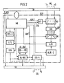
- FIG. 2 shows the block diagram of an autonomous line connection module ALA, which, among other things, has a microcomputer MR.
- the microcomputer MR is connected for data exchange with the central computer module ZR and the other modules with the data bus DB.
- the autonomous line connection module ALA is controlled via the control line ASL (module select) from the central computer module ZR.
- the eight signaling lines ML shown here are connected via a controllable analog switch AS to the line interface device LAE, to which the line voltage LSP is applied.
- the eight lines are routed to a line multiplexer LM which can be controlled by the microcomputer MR via a first address line ADR1.
- the line multiplexer LN is connected to the microcomputer MR via an analog / digital converter A / D.
- control lines STL to which control elements or devices are connected, are connected to a control line connection device STL-A, which is directly controlled by the microcomputer MR and is also connected to the first address line ADR1.
- Certain control lines can also be connected directly to the signal bus SB via the marshalling matrix, which is not specifically shown here.
- the alarm display device AL-ANZ is connected to the alarm output circuit AL-AUS, which in turn is controlled directly by the microcomputer MR.
- the alarm output circuit AL-AUS is connected to the address line ADR1.
- the alarm output circuit AL-AUS and the control line connection device STL-A provide the So-called "C-output" represents. If there is an alarm message, the alarm is sent as a so-called collective alarm directly to the signal bus SB via the alarm output circuit AL-OFF. At the same time, an alarm is transmitted from a specific detection line during the cyclical query from the central computer module via the central computer module to the operating and display module BA.
- the alarm is displayed on the display of the control and display module with details of the triggering signal line of an autonomous interface module and, if individual identification is provided, the number of the triggering detector.
- the triggering signal line (ML) is also shown on the alarm display AL-ANZ of the relevant autonomous line connection module ALA.
- a display of the individual detectors is not provided there because the triggering detector (s) are displayed on the control panel of the operating and display module BA.
- each module has the controllable analog switch AS and a monitoring device for alarm or short circuit AL / KU, which periodically simulates an interruption, a short circuit and an alarm for the respective signal line, controlled by the microcomputer MR.
- the microcomputer MR is connected via a second address line ADR2 and a line for control command STB to a switch-off flip-flop AFF which drives the analog switch AS.
- the line multiplexer LM is controlled via the first address line ABR1 and is connected to the analog switch AS via the line interface device LAE.
- the two independent address controls ensure increased security, because the function of the line multiplex is due to the two independent address lines verifiable.
- the signals coming from the line multiplexer LN and converted in the analog / digital converter A / D are evaluated in the microcomputer MR.
- the monitoring device for an alarm or short circuit AL / K-Ü is acted upon by the microcomputer MR and connected to the analog-digital converter A / D.
- a fault monitoring device ST ⁇ -Ü is provided in the autonomous line connection module ALA, which is connected to the microcomputer MR.
- the outputs of the fault monitoring device ST ⁇ -Ü lead both to the data bus DB and to the signal bus SB.
- the line type switch is set using the LPS line programming switch (e.g. a 16 DIP-Fix switch).
- LPS line programming switch e.g. a 16 DIP-Fix switch.
- the micro-computer MR controls the respective message lines ML cyclically and detects an alarm, short circuit or line break on one of the message lines ML by means of the monitoring device for alarm or short-circuit AL / K-Ü and the micro-computer MR and stored in the register of the microcomputer MR with the associated address.
- the data are transmitted via the data bus DB to the central computer module ZR and from there to the operating and display module BA for display and alarm signaling. If an alarm is triggered by a detector in a detection line, it is also sent directly to the signal bus SB via the alarm output circuit AL-AUS of the line connection module ALA as a so-called collective alarm.
- the fault monitoring device ST ⁇ -Ü has the task, when a fault occurs, e.g. the failure of the module or the microcomputer to identify and forward the fault.
- a fault occurs, e.g. the failure of the module or the microcomputer to identify and forward the fault.
- the microcomputer MR As long as the microcomputer MR is intact, fault messages are sent from the microcomputer to the data bus DB. Faulty or failed modules and faulty signal lines with address details are displayed on the operating and display module. If the microcomputer fails, this fault is sent directly to the Signalbus.SB. This disturbance can also act on the control line ASL, so that the autonomous line connection module with the failed microcomputer, for example, cannot be controlled.
- fault messages such as a short circuit or line break in a detection line or faults in a module of the autonomous interface module, are reported to the central computer module via the microcomputer and the data bus. Otherwise, a fault is given directly to the signal bus as a so-called collective fault and displayed directly on the display panel of the control and display module
- the modules in the test field are adjusted. This eliminates the need for adjustment during assembly or maintenance. If a line interface module is to be replaced, i.e. removed, the data stored in the microcomputer of the module, such as the line setpoints, must not be lost. For this reason, the control panel of the control and display module BA has a command button BT which causes the stored data in the line connection module ALA to be read out and read into a memory provided for this purpose in the central computer module ZR. In addition, it must be entered on the control panel which line connection module is to be removed. A visual display on pulling module lights up so that no wrong module is accidentally removed.
- the central computer ZR sets the data traffic on the data bus DB while the optical display is lighting up, so that no data is falsified by the removal and insertion of a module. A newly inserted line connection module is then written on command (BT) with the data transferred into the central computer module, so that a new measurement is not necessary.
- the modules are easily interchangeable, on the other hand, additional line interface modules can be added to the control center if required. Since each module works autonomously, the data exchange takes place via two separate data channels, the modules monitor themselves and, moreover, the central computer module routinely checks the functionality of the other modules, the highest level of security is guaranteed.
- the central computer module controls the individual modules via the data bus by giving an enable signal via the respective control line so that they recognize that it is their turn.
- the central computer module also controls the read and write signals. The synchronization during data exchange is carried out via acknowledgment signals.
- Messages are generated by the individual modules and can also be passed on to other modules by the central computer module. For example, the message that the system is armed is signaled by the block lock connection module to the individual line connection modules via the central computer module.
Landscapes
- Business, Economics & Management (AREA)
- Emergency Management (AREA)
- Physics & Mathematics (AREA)
- General Physics & Mathematics (AREA)
- Alarm Systems (AREA)
Priority Applications (1)
| Application Number | Priority Date | Filing Date | Title |
|---|---|---|---|
| AT83109277T ATE21459T1 (de) | 1982-09-22 | 1983-09-19 | Multiprozessorsystem fuer gefahrenmeldeanlagen. |
Applications Claiming Priority (2)
| Application Number | Priority Date | Filing Date | Title |
|---|---|---|---|
| DE19823235120 DE3235120A1 (de) | 1982-09-22 | 1982-09-22 | Multiprozessorsystem fuer gefahrenmeldeanlagen |
| DE3235120 | 1982-09-22 |
Publications (2)
| Publication Number | Publication Date |
|---|---|
| EP0106191A1 true EP0106191A1 (fr) | 1984-04-25 |
| EP0106191B1 EP0106191B1 (fr) | 1986-08-13 |
Family
ID=6173885
Family Applications (1)
| Application Number | Title | Priority Date | Filing Date |
|---|---|---|---|
| EP83109277A Expired EP0106191B1 (fr) | 1982-09-22 | 1983-09-19 | Système de multiprocesseur pour l'installation d'un avertisseur de danger |
Country Status (3)
| Country | Link |
|---|---|
| EP (1) | EP0106191B1 (fr) |
| AT (1) | ATE21459T1 (fr) |
| DE (2) | DE3235120A1 (fr) |
Cited By (3)
| Publication number | Priority date | Publication date | Assignee | Title |
|---|---|---|---|---|
| EP0175657A1 (fr) * | 1984-09-14 | 1986-03-26 | I.T.C. S.p.A. | Interface entre un ou plusieurs ordinateurs et capteurs et déclencheurs dans des dispositifs de contrôle |
| DE29508882U1 (de) * | 1995-05-30 | 1996-01-25 | Popp + Co GmbH, 95460 Bad Berneck | Adressierbarer Knoten |
| US12017036B2 (en) | 2012-09-25 | 2024-06-25 | Fresenius Medical Care Holdings, Inc. | Blood flow reversal valves and related systems and methods |
Families Citing this family (2)
| Publication number | Priority date | Publication date | Assignee | Title |
|---|---|---|---|---|
| DE4443391A1 (de) * | 1994-12-06 | 1996-06-13 | Aeg Sensorsysteme Gmbh | System mit einer Mehrzahl von Schlössern |
| DE102008062725A1 (de) * | 2008-12-18 | 2010-07-01 | Eads Deutschland Gmbh | Verfahren zur Datenübertragung auf einer Datenübertragungsverbindung sowie Datenübertragungseinheit |
Citations (5)
| Publication number | Priority date | Publication date | Assignee | Title |
|---|---|---|---|---|
| US3641570A (en) * | 1969-04-02 | 1972-02-08 | Francis T Thompson | Alarm system |
| US4163226A (en) * | 1977-09-02 | 1979-07-31 | Statitrol Division Emerson Electric Co. | Alarm condition detecting apparatus and method |
| EP0004912A1 (fr) * | 1978-04-19 | 1979-10-31 | Siemens Aktiengesellschaft | Avertisseur de danger |
| EP0004909A1 (fr) * | 1978-04-19 | 1979-10-31 | Siemens Aktiengesellschaft | Avertisseur de danger |
| EP0048869A2 (fr) * | 1980-09-30 | 1982-04-07 | Siemens Aktiengesellschaft | Système de multiprocesseur, en particulier comprenant un nombre de microprocesseurs |
-
1982
- 1982-09-22 DE DE19823235120 patent/DE3235120A1/de not_active Withdrawn
-
1983
- 1983-09-19 DE DE8383109277T patent/DE3365311D1/de not_active Expired
- 1983-09-19 AT AT83109277T patent/ATE21459T1/de not_active IP Right Cessation
- 1983-09-19 EP EP83109277A patent/EP0106191B1/fr not_active Expired
Patent Citations (6)
| Publication number | Priority date | Publication date | Assignee | Title |
|---|---|---|---|---|
| US3641570A (en) * | 1969-04-02 | 1972-02-08 | Francis T Thompson | Alarm system |
| US4163226A (en) * | 1977-09-02 | 1979-07-31 | Statitrol Division Emerson Electric Co. | Alarm condition detecting apparatus and method |
| EP0004912A1 (fr) * | 1978-04-19 | 1979-10-31 | Siemens Aktiengesellschaft | Avertisseur de danger |
| EP0004909A1 (fr) * | 1978-04-19 | 1979-10-31 | Siemens Aktiengesellschaft | Avertisseur de danger |
| DE2817121A1 (de) * | 1978-04-19 | 1979-10-31 | Siemens Ag | Gefahrenmeldeanlage |
| EP0048869A2 (fr) * | 1980-09-30 | 1982-04-07 | Siemens Aktiengesellschaft | Système de multiprocesseur, en particulier comprenant un nombre de microprocesseurs |
Cited By (3)
| Publication number | Priority date | Publication date | Assignee | Title |
|---|---|---|---|---|
| EP0175657A1 (fr) * | 1984-09-14 | 1986-03-26 | I.T.C. S.p.A. | Interface entre un ou plusieurs ordinateurs et capteurs et déclencheurs dans des dispositifs de contrôle |
| DE29508882U1 (de) * | 1995-05-30 | 1996-01-25 | Popp + Co GmbH, 95460 Bad Berneck | Adressierbarer Knoten |
| US12017036B2 (en) | 2012-09-25 | 2024-06-25 | Fresenius Medical Care Holdings, Inc. | Blood flow reversal valves and related systems and methods |
Also Published As
| Publication number | Publication date |
|---|---|
| ATE21459T1 (de) | 1986-08-15 |
| DE3235120A1 (de) | 1984-03-22 |
| EP0106191B1 (fr) | 1986-08-13 |
| DE3365311D1 (en) | 1986-09-18 |
Similar Documents
| Publication | Publication Date | Title |
|---|---|---|
| EP0485878B1 (fr) | Procédé pour déterminer la configuration des détecteurs d'un système d'alarme | |
| EP0875810B1 (fr) | Méthode et dispositif de surveillance d'une installation comprenant plusieurs unités fonctionnelles | |
| DE3706325C2 (fr) | ||
| EP0972389B1 (fr) | Systeme de commande de securite et procede pour la mise en oeuvre d'un tel systeme | |
| DE2817089A1 (de) | Gefahrenmeldeanlage | |
| EP0004909B1 (fr) | Avertisseur de danger | |
| EP0330164B1 (fr) | Dispositif de mise hors circuit partielle d'un système de signalisation routière | |
| EP0240833B1 (fr) | Dispositif de surveillance pour la surveillance du fonctionnement de dispositifs de transmission de la technique de transmission d'informations | |
| EP0106191B1 (fr) | Système de multiprocesseur pour l'installation d'un avertisseur de danger | |
| DE3611949A1 (de) | Datenuebertragungsverfahren und datenuebertragungsvorrichtung | |
| EP0770942A2 (fr) | Agencement pous saisir et/ou traîter des signaux provenant de composantes électriques, qui remplissent des fins de sécurité technique ou des conditions pour les appareils de l'installation | |
| WO1979000902A1 (fr) | Dispositif d'alarme partiellement amovible avec protection contre le non-fonctionnement, la panne, le sabotage et la fausse alarme | |
| EP0004912B1 (fr) | Avertisseur de danger | |
| DE3007960C2 (de) | Elektronisches Stellwerk | |
| DE3415819C2 (de) | Brandmeldeeinrichtung | |
| EP0193835B1 (fr) | Dispositif de rassemblement d'informations de surveillance dans des systèmes de transmission | |
| DE2400604A1 (de) | Elektronisches fehleranzeigesystem | |
| DE2817053C2 (de) | Gefahrenmeldeanlage | |
| DE2023117A1 (de) | Ausfallsicheres Steuersystem zur UEbertragung von digitalen Informationen | |
| DE4426466A1 (de) | Anordnung und Verfahren zum Betreiben von Gefahrenmeldern | |
| EP0156388A2 (fr) | Agencement de traitement de données à sécurité de signal techniquement assurée | |
| EP1038223B1 (fr) | Systeme de surveillance pour une cellule d'ajustage | |
| DE10200091A1 (de) | Einrichtung zum Überwachen und Steuern von Maschinen bzw. maschinellen Anlagen | |
| DE1524140C3 (de) | Einrichtung zur Wartungsprüfung einer Datenverarbeitungsanlage mit mehreren Speicher- und Steuermoäuln | |
| DE2148981C3 (de) | Verfahren zur Erfassung und Steuerung de r Funktionszustande einzelner Systemeinheiten eines programmgesteuerten Verarbeitungssystems |
Legal Events
| Date | Code | Title | Description |
|---|---|---|---|
| PUAI | Public reference made under article 153(3) epc to a published international application that has entered the european phase |
Free format text: ORIGINAL CODE: 0009012 |
|
| AK | Designated contracting states |
Designated state(s): AT CH DE IT LI NL SE |
|
| 17P | Request for examination filed |
Effective date: 19840824 |
|
| GRAA | (expected) grant |
Free format text: ORIGINAL CODE: 0009210 |
|
| AK | Designated contracting states |
Kind code of ref document: B1 Designated state(s): AT CH DE IT LI NL SE |
|
| REF | Corresponds to: |
Ref document number: 21459 Country of ref document: AT Date of ref document: 19860815 Kind code of ref document: T |
|
| REF | Corresponds to: |
Ref document number: 3365311 Country of ref document: DE Date of ref document: 19860918 |
|
| ITF | It: translation for a ep patent filed | ||
| PLBE | No opposition filed within time limit |
Free format text: ORIGINAL CODE: 0009261 |
|
| STAA | Information on the status of an ep patent application or granted ep patent |
Free format text: STATUS: NO OPPOSITION FILED WITHIN TIME LIMIT |
|
| 26N | No opposition filed | ||
| ITTA | It: last paid annual fee | ||
| PGFP | Annual fee paid to national office [announced via postgrant information from national office to epo] |
Ref country code: AT Payment date: 19940824 Year of fee payment: 12 |
|
| PGFP | Annual fee paid to national office [announced via postgrant information from national office to epo] |
Ref country code: SE Payment date: 19940829 Year of fee payment: 12 |
|
| PGFP | Annual fee paid to national office [announced via postgrant information from national office to epo] |
Ref country code: NL Payment date: 19940930 Year of fee payment: 12 |
|
| PGFP | Annual fee paid to national office [announced via postgrant information from national office to epo] |
Ref country code: DE Payment date: 19941118 Year of fee payment: 12 |
|
| PGFP | Annual fee paid to national office [announced via postgrant information from national office to epo] |
Ref country code: CH Payment date: 19941216 Year of fee payment: 12 |
|
| EAL | Se: european patent in force in sweden |
Ref document number: 83109277.0 |
|
| PG25 | Lapsed in a contracting state [announced via postgrant information from national office to epo] |
Ref country code: AT Effective date: 19950919 |
|
| PG25 | Lapsed in a contracting state [announced via postgrant information from national office to epo] |
Ref country code: SE Effective date: 19950920 |
|
| PG25 | Lapsed in a contracting state [announced via postgrant information from national office to epo] |
Ref country code: LI Effective date: 19950930 Ref country code: CH Effective date: 19950930 |
|
| PG25 | Lapsed in a contracting state [announced via postgrant information from national office to epo] |
Ref country code: NL Effective date: 19960401 |
|
| REG | Reference to a national code |
Ref country code: CH Ref legal event code: PL |
|
| PG25 | Lapsed in a contracting state [announced via postgrant information from national office to epo] |
Ref country code: DE Effective date: 19960601 |
|
| NLV4 | Nl: lapsed or anulled due to non-payment of the annual fee |
Effective date: 19960401 |
|
| EUG | Se: european patent has lapsed |
Ref document number: 83109277.0 |