EP0048869A2 - Système de multiprocesseur, en particulier comprenant un nombre de microprocesseurs - Google Patents
Système de multiprocesseur, en particulier comprenant un nombre de microprocesseurs Download PDFInfo
- Publication number
- EP0048869A2 EP0048869A2 EP81107161A EP81107161A EP0048869A2 EP 0048869 A2 EP0048869 A2 EP 0048869A2 EP 81107161 A EP81107161 A EP 81107161A EP 81107161 A EP81107161 A EP 81107161A EP 0048869 A2 EP0048869 A2 EP 0048869A2
- Authority
- EP
- European Patent Office
- Prior art keywords
- computer
- computer system
- work
- operating
- task
- Prior art date
- Legal status (The legal status is an assumption and is not a legal conclusion. Google has not performed a legal analysis and makes no representation as to the accuracy of the status listed.)
- Granted
Links
Images
Classifications
-
- G—PHYSICS
- G06—COMPUTING OR CALCULATING; COUNTING
- G06F—ELECTRIC DIGITAL DATA PROCESSING
- G06F13/00—Interconnection of, or transfer of information or other signals between, memories, input/output devices or central processing units
- G06F13/38—Information transfer, e.g. on bus
- G06F13/42—Bus transfer protocol, e.g. handshake; Synchronisation
- G06F13/4204—Bus transfer protocol, e.g. handshake; Synchronisation on a parallel bus
- G06F13/4208—Bus transfer protocol, e.g. handshake; Synchronisation on a parallel bus being a system bus, e.g. VME bus, Futurebus, Multibus
- G06F13/4213—Bus transfer protocol, e.g. handshake; Synchronisation on a parallel bus being a system bus, e.g. VME bus, Futurebus, Multibus with asynchronous protocol
-
- G—PHYSICS
- G06—COMPUTING OR CALCULATING; COUNTING
- G06F—ELECTRIC DIGITAL DATA PROCESSING
- G06F13/00—Interconnection of, or transfer of information or other signals between, memories, input/output devices or central processing units
- G06F13/14—Handling requests for interconnection or transfer
- G06F13/20—Handling requests for interconnection or transfer for access to input/output bus
- G06F13/28—Handling requests for interconnection or transfer for access to input/output bus using burst mode transfer, e.g. direct memory access DMA, cycle steal
-
- G—PHYSICS
- G06—COMPUTING OR CALCULATING; COUNTING
- G06F—ELECTRIC DIGITAL DATA PROCESSING
- G06F13/00—Interconnection of, or transfer of information or other signals between, memories, input/output devices or central processing units
- G06F13/14—Handling requests for interconnection or transfer
- G06F13/36—Handling requests for interconnection or transfer for access to common bus or bus system
- G06F13/362—Handling requests for interconnection or transfer for access to common bus or bus system with centralised access control
- G06F13/364—Handling requests for interconnection or transfer for access to common bus or bus system with centralised access control using independent requests or grants, e.g. using separated request and grant lines
-
- G—PHYSICS
- G06—COMPUTING OR CALCULATING; COUNTING
- G06F—ELECTRIC DIGITAL DATA PROCESSING
- G06F15/00—Digital computers in general; Data processing equipment in general
- G06F15/16—Combinations of two or more digital computers each having at least an arithmetic unit, a program unit and a register, e.g. for a simultaneous processing of several programs
- G06F15/161—Computing infrastructure, e.g. computer clusters, blade chassis or hardware partitioning
Definitions
- the present invention relates' to a multi-computer system, in particular with a plurality of microcomputers, in which an all computers connecting bus line system is provided and which has a central, connected to this bus line system unit, by means of which all functions relevant computer can be performed.
- the present invention has for its object to provide a multi-computer system in which an operating computer is designed and connected to the bus line system of the actual multi-computer system so that diagnosis and maintenance as well as operation control and communication between the individual computers can be carried out optimally, whereby a relatively simple and clear system structure should be retained.
- the company computer should also be able to perform tasks op to distribute timely to the individual computers, to make changes in the priority order in the interest of the least possible processing time and in the interest of the urgency of operations and, if necessary, to temporarily store data that cannot be deducted in time in order to relieve the load on the individual computers in its own memory.
- the object on which the invention is based is achieved by a multicomputer system, in particular with a multiplicity of microcomputers, in which a bus line system connecting all computers is provided and which has a central unit connected to this bus line system, by means of which all computer-related functions can be carried out.
- the multi-computer system is characterized in that the central unit has the task of an operating computer, the operating computer performing, in addition to the known central function of maintenance or diagnosis of the entire multi-computer system, also a central function which relates to the control of communication between the computers that the bus line system has, in addition to the address line known per se for such a bus line system, a data line and a bus control line, further lines, namely a transfer control line, an address transmitter control line and an access signal line, that the operating computer maintains a list for carrying out the communication, which the operating computer, among other things also used to transfer a task that cannot be solved by a computer to another computer, and that the computers each have a communication field.
- the invention offers the advantage that a multi-computer system is available, the diagnosis, maintenance, operation control and can optimally carry out communication between the individual computers with a particularly simple and clear system structure.
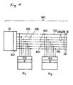
- FIG. 1 shows a block diagram of the essential components of the multi-computer system MRS for a preferred exemplary embodiment of the invention.
- the individual computers of the MRS multi-computer system are connected to one another via a bus line system BS - also called transfer bus in the following.
- the operation computer BR carries out the handling of the functions mentioned at the outset (communication, operation, diagnosis and maintenance).
- the transfer bus is the physical basis for this.
- up to 16 work computers AR namely AR a ... AR 15 , are connected. This number can be increased, however, if the address lines for "sending computer" and "receiving computer” are expanded and the identification of the work computer AR is coded.
- the operating computer BR is connected to the transfer bus with a bus BSST control, the AR 0 ... AR 15 work computers are each connected to a BSA bus adapter that is individually assigned to them.
- the terms “sending computer” and “receiving computer” in the following describe the respective operating state of the computers during communication between these computers.
- the individual computers communicate via a communication field KF in each work computer AR.
- the communication field KF is a defined area in the read / write memory, which contains the supply parameters required for the data transfer.
- the operating computer BR knows the starting addresses of the communication fields KF in the work computer AR.
- the operating computer BR In addition to the central function of maintenance or diagnosis of the entire multi-computer system MRS, which is known per se, the operating computer BR also has a central function which relates to the control of the communication between the computers, namely the work computers AR.
- the bus line system BS In addition to the address line ADRS / ADRE known per se for such a bus line system BS, a data line DAT and a bus control line BUST, the bus line system BS has further lines, namely a transfer control line TRST, an address transmitter control line AGST and an access signal line SPEA.
- the operating computer BR maintains a list for carrying out the communication, which it also uses, among other things, to perform a task that cannot be solved by a computer, for example AR O ', by another computer, eg B. AR 15 to transmit.
- the list contains information about which task or which tasks can or can be solved by which computer or which work computer AR.
- the list also contains information which provides information about the respective free / busy state of each of the work computers AR.
- the respective free / busy state of each of the work computers AR is queried as required by the operating computer BR.
- the list also contains information tion for converting the identifier of a work computer AR into its address and also information about the start address of the communication field KF of the work computer AR in question.
- the communication field KF can have any structure. It preferably has a predetermined, fixed format. In the communication field KF is u. a. contain an indication of how long the data field to be transferred is.
- the operating computer BR When a request is made by a work computer AR, the operating computer BR reads in the content of the communication field KF of the requesting work computer AR in question based on the information in the list and then makes a decision based on the information in the list and the information in the relevant communication field KF whether or not the request underlying task can be transferred directly to another work computer AR or whether the relevant data must be buffered.
- the decision as to whether the task in question is transmitted directly to a work computer AR relating to this task or whether the relevant data is temporarily stored in the operating computer BR is made dependent on the type of task. This decision can also be made dependent on the application for the entire multi-computer system MRS. According to the invention, it can also be made dependent on the priority rank of the task in question.
- Another development of the invention provides that an already existing sequence of priorities for the distribution of tasks is changed by a new task due to the priority rank of this task within the operating computer BR.
- the address line ADRS / ADRE is divided into a sending computer address line ADRS and a receiving computer address line ADRE, via which address lines the computers involved in communication or data transfer can be called.
- an interrupt signal can be transmitted from the operating computer BR to a work computer AR or vice versa via the transfer control line TRST.
- the address transmitter control line AGST is intended to transmit a switchover signal when an address transmitter AG is loaded within the work computer AR to this work computer AR.
- the address generator AG is incremented during a data transfer. Access signals are transmitted via the access signal line SPEA for the purpose of free access to the memory of any work computer AR.
- the data transfer the two respective memories in question are controlled simultaneously, data from one of the two memories being read and this data being written into the other memory, for which purpose a write signal is derived from the acknowledgment signal to the read signal.
- the operating computer BR has direct access to the memory of a work computer, e.g. B. ARp, for reading or writing, the operating computer BR the conditions of the internal bus of the relevant work computer, for. B. AR 9 met.
- the operating computer BR the memory of the relevant work computer, for. B. AR 0 , with one or more command cycles in the same way as the operating computer BR addresses its own memory.
- the operating computer BR does not use one or more command cycles, but rather one or more direct memory accesses (DMA cycles) to save the memory of the relevant work computer, e.g. B. AR 0 .
- the memory of the operating computer BR can advantageously during a data transfer between two work computers, for. B. AR 0 and AR 15 , all data parallel to the memory of the receiving computer concerned, z. B. AR 15 , for the purpose of data backup.
- all work computers AR a ... AR 15 can send a request signal for the purpose of a data transfer to the operating computer BR independently of time, without the operating sequence being impaired.
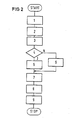
- FIG. 2 shows a flow chart for a data transfer or a communication cycle between two computers.
- the relevant work computer AR sends an interrupt signal to the operating computer BR. If “1”, the operating computer BR calls the content of the communicati onsfeldes KF and secures the communication field KF against a change of the content. If “2”, the operating computer BR determines the receiving computer relevant to the task. The operating computer reads the content of the communication field KF of this receiving computer at "3" and secures this communication field KF against a change in its content. With decision diamond “4", the operating computer BR then checks whether the transfer order can be carried out under the existing circumstances.
- the operating computer BR carries out the data transfer at "5" by means of a direct memory access (DMA) and sends a corresponding acknowledgment signal in each case into the communication field KF of the transmitter computer and of the receiving computer. Then, at "7", the operating computer BR sends an interrupt signal to both the sending computer and the receiving computer. This process also begins immediately if it has been decided in decision diamond "4" that the transfer order cannot be carried out (output "N").
- DMA direct memory access
- the operating computer BR writes a message as an acknowledgment in the communication field KF of the sending computer, optionally also in the communication field KF of the receiving computer, and then sends the interrupt signal at "7" to the sending computer and the receiving computer, as previously described.
- both the sending computer and the receiving computer evaluate the respective receipts and received at "8". reset the lock that previously occurred in their communication field KF.
- the operating computer waits at "9" for an acknowledgment from the sending computer and the receiving computer as a signal for the activation that has occurred on these computers. When this acknowledgment has arrived, the operating computer BR ends the cycle with "STOP".
- the memory of the operating computer BR can advantageously can also be used to temporarily store data from a sending computer in the event that the receiving computer in question is not ready to receive in order to relieve the sending computer.
- the operating computer BR is doubled in a manner known per se in order to increase operational safety.
- An advantageous implementation of the multi-computer system MRS results from the fact that the transistor functions required for communication within the multi-computer system MRS are each arranged on a chip, namely a chip of a first type for the work computer AR and a second type for the operating computer BR.
- the work computers AR are relieved of time, which can be advantageous in many applications for such a multi-computer system MRS.
- an advantageous saving of storage space in the operating computer BR and a substantial saving of time can result from the direct access of the operating computer BR provided according to the invention to the memories of the working computers AR.
Landscapes
- Engineering & Computer Science (AREA)
- Theoretical Computer Science (AREA)
- Physics & Mathematics (AREA)
- General Engineering & Computer Science (AREA)
- General Physics & Mathematics (AREA)
- Computer Hardware Design (AREA)
- Mathematical Physics (AREA)
- Software Systems (AREA)
- Hardware Redundancy (AREA)
- Multi Processors (AREA)
Applications Claiming Priority (2)
| Application Number | Priority Date | Filing Date | Title |
|---|---|---|---|
| DE19803036911 DE3036911A1 (de) | 1980-09-30 | 1980-09-30 | Mehrrechnersystem, insbesondere mit einer vielzahl von mikrorechnern |
| DE3036911 | 1980-09-30 |
Publications (3)
| Publication Number | Publication Date |
|---|---|
| EP0048869A2 true EP0048869A2 (fr) | 1982-04-07 |
| EP0048869A3 EP0048869A3 (en) | 1984-07-25 |
| EP0048869B1 EP0048869B1 (fr) | 1988-07-27 |
Family
ID=6113236
Family Applications (1)
| Application Number | Title | Priority Date | Filing Date |
|---|---|---|---|
| EP19810107161 Expired EP0048869B1 (fr) | 1980-09-30 | 1981-09-10 | Système de multiprocesseur, en particulier comprenant un nombre de microprocesseurs |
Country Status (2)
| Country | Link |
|---|---|
| EP (1) | EP0048869B1 (fr) |
| DE (1) | DE3036911A1 (fr) |
Cited By (3)
| Publication number | Priority date | Publication date | Assignee | Title |
|---|---|---|---|---|
| EP0106191A1 (fr) * | 1982-09-22 | 1984-04-25 | Siemens Aktiengesellschaft | Système de multiprocesseur pour l'installation d'un avertisseur de danger |
| EP0107304A3 (fr) * | 1982-09-06 | 1985-05-22 | Tycom Corporation Limited | Petit ordinateur |
| WO2000017759A3 (fr) * | 1998-09-18 | 2000-08-10 | Pixelfusion Ltd | Appareil pour systeme informatique |
Families Citing this family (3)
| Publication number | Priority date | Publication date | Assignee | Title |
|---|---|---|---|---|
| DE3538214C2 (de) * | 1984-10-30 | 1994-06-16 | Mitsubishi Electric Corp | Multiprozessorsystem |
| DE4035565A1 (de) * | 1990-11-08 | 1992-05-14 | Sbs Computer Gmbh | Vernetztes system |
| DE4431206A1 (de) * | 1994-09-02 | 1996-03-07 | Sel Alcatel Ag | Verfahren zur Bestimmung einer Verbindungsidentifikation in einem Mehrrechnersystem und Mehrrechnersystem dafür |
Family Cites Families (8)
| Publication number | Priority date | Publication date | Assignee | Title |
|---|---|---|---|---|
| US3530438A (en) * | 1965-12-13 | 1970-09-22 | Sperry Rand Corp | Task control |
| US3449722A (en) * | 1966-05-02 | 1969-06-10 | Honeywell Inc | Electronic multiprocessing apparatus including common queueing technique |
| US3634830A (en) * | 1969-06-13 | 1972-01-11 | Ibm | Modular computer sharing system with intercomputer communication control apparatus |
| US3753234A (en) * | 1972-02-25 | 1973-08-14 | Reliance Electric Co | Multicomputer system with simultaneous data interchange between computers |
| DE2546202A1 (de) * | 1975-10-15 | 1977-04-28 | Siemens Ag | Rechnersystem aus mehreren miteinander verbundenen und zusammenwirkenden einzelrechnern und verfahren zum betrieb des rechnersystems |
| DE2644188B2 (de) * | 1976-09-30 | 1980-06-19 | Siemens Ag, 1000 Berlin Und 8000 Muenchen | Mehrbenutzer-Mehrprozessor-System |
| DE2713304A1 (de) * | 1977-03-25 | 1978-09-28 | Siemens Ag | Mehrrechnersystem |
| DE2805705C2 (de) * | 1978-02-10 | 1987-01-29 | Patelhold Patentverwertungs- und Elektro-Holding AG, Glarus | Datenübertragungsverfahren zwischen mehreren gleichberechtigten Teilnehmern |
-
1980
- 1980-09-30 DE DE19803036911 patent/DE3036911A1/de not_active Ceased
-
1981
- 1981-09-10 EP EP19810107161 patent/EP0048869B1/fr not_active Expired
Cited By (5)
| Publication number | Priority date | Publication date | Assignee | Title |
|---|---|---|---|---|
| EP0107304A3 (fr) * | 1982-09-06 | 1985-05-22 | Tycom Corporation Limited | Petit ordinateur |
| EP0106191A1 (fr) * | 1982-09-22 | 1984-04-25 | Siemens Aktiengesellschaft | Système de multiprocesseur pour l'installation d'un avertisseur de danger |
| WO2000017759A3 (fr) * | 1998-09-18 | 2000-08-10 | Pixelfusion Ltd | Appareil pour systeme informatique |
| US7054969B1 (en) | 1998-09-18 | 2006-05-30 | Clearspeed Technology Plc | Apparatus for use in a computer system |
| US7346722B2 (en) | 1998-09-18 | 2008-03-18 | Clearspeed Technology Plc | Apparatus for use in a computer systems |
Also Published As
| Publication number | Publication date |
|---|---|
| EP0048869B1 (fr) | 1988-07-27 |
| DE3036911A1 (de) | 1982-05-13 |
| EP0048869A3 (en) | 1984-07-25 |
Similar Documents
| Publication | Publication Date | Title |
|---|---|---|
| DE68928316T2 (de) | Vorrichtung zur anteiligen nutzung von betriebsmitteln eines hauptrechners zwischen einer vielzahl von entfernten rechnern | |
| DE3851928T2 (de) | Steuerung von asynchron arbeitenden Peripheriegeräten. | |
| DE3751091T2 (de) | Übertragungsprotokoll zwischen Prozessoren. | |
| DE2641741C2 (de) | Rechenanlage aus mehreren miteinander über ein Sammelleitungssystem verbundenen und zusammenwirkenden Einzelrechnern und einem Steuerrechner | |
| DE3642324C2 (de) | Multiprozessoranlage mit Prozessor-Zugriffssteuerung | |
| DE69132195T2 (de) | System für verteilte Mehrfachrechnerkommunikation | |
| DE69024078T2 (de) | Mehrprozessoranordnung mit Vervielfältigung von globalen Daten und mit zwei Stufen von Adressübersetzungseinheiten | |
| DE69519117T2 (de) | Ein Rechnersystem | |
| EP0006164B1 (fr) | Système multiprocesseur avec mémoires utilisables en commun | |
| DE3301628A1 (de) | Schaltungsanordnung fuer den datenaustausch zwischen zwei rechnern | |
| EP0179936A1 (fr) | Méthode et dispositif pour le contrôle d'un bus en commun | |
| DE69031782T2 (de) | Verfahren zum Ersetzen von Speichermodulen in einem Computersystem und Computersystem zur Durchführung des Verfahrens | |
| DE3127349A1 (de) | Signalverarbeitungssystem mit verteilten elementen | |
| DE2913288A1 (de) | Multiprozessorsystem | |
| DE2523372B2 (de) | Eingabe-ZAusgabe-Anschlußsteuereinrichtung | |
| DE69016978T2 (de) | Sicheres Datenschnellschreibverfahren für Massenspeichereinrichtung und ein dieses Verfahren ausführendes Computersystem. | |
| DE3142504A1 (de) | Mehrfachplattenspeicher-uebertragungssystem | |
| EP0185260A2 (fr) | Interface pour le transfert direct d'informations | |
| EP0048869B1 (fr) | Système de multiprocesseur, en particulier comprenant un nombre de microprocesseurs | |
| DE69719123T2 (de) | System zur Datenverarbeitung und -kommunikation mit PCI-Hochdurchsatzbus | |
| DE2749884C2 (fr) | ||
| EP1308846B1 (fr) | Dispositif de transfert de données | |
| DD142135A3 (de) | Mehrrechnerkopplung | |
| DE2713304A1 (de) | Mehrrechnersystem | |
| DE3788346T2 (de) | E/a-system zur abladung von betriebssystemfunktionen. |
Legal Events
| Date | Code | Title | Description |
|---|---|---|---|
| PUAI | Public reference made under article 153(3) epc to a published international application that has entered the european phase |
Free format text: ORIGINAL CODE: 0009012 |
|
| 17P | Request for examination filed |
Effective date: 19811030 |
|
| AK | Designated contracting states |
Designated state(s): BE FR GB IT NL SE |
|
| PUAL | Search report despatched |
Free format text: ORIGINAL CODE: 0009013 |
|
| AK | Designated contracting states |
Designated state(s): BE FR GB IT NL SE |
|
| 17Q | First examination report despatched |
Effective date: 19860821 |
|
| R17C | First examination report despatched (corrected) |
Effective date: 19870224 |
|
| GRAA | (expected) grant |
Free format text: ORIGINAL CODE: 0009210 |
|
| AK | Designated contracting states |
Kind code of ref document: B1 Designated state(s): BE FR GB IT NL SE |
|
| GBT | Gb: translation of ep patent filed (gb section 77(6)(a)/1977) | ||
| ET | Fr: translation filed | ||
| ITF | It: translation for a ep patent filed | ||
| PLBE | No opposition filed within time limit |
Free format text: ORIGINAL CODE: 0009261 |
|
| STAA | Information on the status of an ep patent application or granted ep patent |
Free format text: STATUS: NO OPPOSITION FILED WITHIN TIME LIMIT |
|
| 26N | No opposition filed | ||
| PGFP | Annual fee paid to national office [announced via postgrant information from national office to epo] |
Ref country code: GB Payment date: 19890831 Year of fee payment: 9 |
|
| PGFP | Annual fee paid to national office [announced via postgrant information from national office to epo] |
Ref country code: SE Payment date: 19890912 Year of fee payment: 9 |
|
| PGFP | Annual fee paid to national office [announced via postgrant information from national office to epo] |
Ref country code: BE Payment date: 19890919 Year of fee payment: 9 |
|
| PGFP | Annual fee paid to national office [announced via postgrant information from national office to epo] |
Ref country code: FR Payment date: 19890928 Year of fee payment: 9 |
|
| ITTA | It: last paid annual fee | ||
| PGFP | Annual fee paid to national office [announced via postgrant information from national office to epo] |
Ref country code: NL Payment date: 19890930 Year of fee payment: 9 |
|
| PG25 | Lapsed in a contracting state [announced via postgrant information from national office to epo] |
Ref country code: GB Effective date: 19900910 |
|
| PG25 | Lapsed in a contracting state [announced via postgrant information from national office to epo] |
Ref country code: SE Effective date: 19900911 |
|
| PG25 | Lapsed in a contracting state [announced via postgrant information from national office to epo] |
Ref country code: BE Effective date: 19900930 |
|
| BERE | Be: lapsed |
Owner name: SIEMENS A.G. BERLIN UND MUNCHEN Effective date: 19900930 |
|
| PG25 | Lapsed in a contracting state [announced via postgrant information from national office to epo] |
Ref country code: NL Effective date: 19910401 |
|
| GBPC | Gb: european patent ceased through non-payment of renewal fee | ||
| NLV4 | Nl: lapsed or anulled due to non-payment of the annual fee | ||
| PG25 | Lapsed in a contracting state [announced via postgrant information from national office to epo] |
Ref country code: FR Effective date: 19910530 |
|
| REG | Reference to a national code |
Ref country code: FR Ref legal event code: ST |
|
| EUG | Se: european patent has lapsed |
Ref document number: 81107161.2 Effective date: 19910527 |