EP0106232A1 - Glühkerze für Brennkraftmaschinen mit Fremdzündung - Google Patents
Glühkerze für Brennkraftmaschinen mit Fremdzündung Download PDFInfo
- Publication number
- EP0106232A1 EP0106232A1 EP83109726A EP83109726A EP0106232A1 EP 0106232 A1 EP0106232 A1 EP 0106232A1 EP 83109726 A EP83109726 A EP 83109726A EP 83109726 A EP83109726 A EP 83109726A EP 0106232 A1 EP0106232 A1 EP 0106232A1
- Authority
- EP
- European Patent Office
- Prior art keywords
- ceramic carrier
- glow plug
- heat sink
- metal core
- combustion chamber
- Prior art date
- Legal status (The legal status is an assumption and is not a legal conclusion. Google has not performed a legal analysis and makes no representation as to the accuracy of the status listed.)
- Granted
Links
- 238000002485 combustion reaction Methods 0.000 title claims abstract description 54
- 239000000919 ceramic Substances 0.000 claims abstract description 65
- 229910052751 metal Inorganic materials 0.000 claims abstract description 37
- 239000002184 metal Substances 0.000 claims abstract description 37
- 239000004020 conductor Substances 0.000 claims abstract description 18
- 238000010438 heat treatment Methods 0.000 claims abstract description 14
- 239000011241 protective layer Substances 0.000 claims abstract description 5
- 229910000906 Bronze Inorganic materials 0.000 claims description 6
- 239000010974 bronze Substances 0.000 claims description 6
- KUNSUQLRTQLHQQ-UHFFFAOYSA-N copper tin Chemical compound [Cu].[Sn] KUNSUQLRTQLHQQ-UHFFFAOYSA-N 0.000 claims description 6
- 239000000463 material Substances 0.000 claims description 6
- 230000005693 optoelectronics Effects 0.000 claims description 5
- 239000007787 solid Substances 0.000 claims description 5
- 229910000831 Steel Inorganic materials 0.000 claims description 3
- ATJFFYVFTNAWJD-UHFFFAOYSA-N Tin Chemical compound [Sn] ATJFFYVFTNAWJD-UHFFFAOYSA-N 0.000 claims description 3
- 229910052782 aluminium Inorganic materials 0.000 claims description 3
- XAGFODPZIPBFFR-UHFFFAOYSA-N aluminium Chemical compound [Al] XAGFODPZIPBFFR-UHFFFAOYSA-N 0.000 claims description 3
- VNNRSPGTAMTISX-UHFFFAOYSA-N chromium nickel Chemical compound [Cr].[Ni] VNNRSPGTAMTISX-UHFFFAOYSA-N 0.000 claims description 3
- 229910052709 silver Inorganic materials 0.000 claims description 3
- 239000004332 silver Substances 0.000 claims description 3
- 239000010959 steel Substances 0.000 claims description 3
- 229910000838 Al alloy Inorganic materials 0.000 claims description 2
- 229910001369 Brass Inorganic materials 0.000 claims description 2
- RYGMFSIKBFXOCR-UHFFFAOYSA-N Copper Chemical compound [Cu] RYGMFSIKBFXOCR-UHFFFAOYSA-N 0.000 claims description 2
- XUIMIQQOPSSXEZ-UHFFFAOYSA-N Silicon Chemical compound [Si] XUIMIQQOPSSXEZ-UHFFFAOYSA-N 0.000 claims description 2
- 239000010951 brass Substances 0.000 claims description 2
- 229910052802 copper Inorganic materials 0.000 claims description 2
- 239000010949 copper Substances 0.000 claims description 2
- 239000000155 melt Substances 0.000 claims description 2
- 229910052710 silicon Inorganic materials 0.000 claims description 2
- 239000010703 silicon Substances 0.000 claims description 2
- 230000002277 temperature effect Effects 0.000 abstract 1
- 238000007789 sealing Methods 0.000 description 13
- 239000000156 glass melt Substances 0.000 description 7
- BASFCYQUMIYNBI-UHFFFAOYSA-N platinum Chemical compound [Pt] BASFCYQUMIYNBI-UHFFFAOYSA-N 0.000 description 6
- 230000007704 transition Effects 0.000 description 6
- 239000000446 fuel Substances 0.000 description 5
- 238000005516 engineering process Methods 0.000 description 4
- 239000000203 mixture Substances 0.000 description 4
- 230000008901 benefit Effects 0.000 description 3
- 239000002609 medium Substances 0.000 description 3
- TWNQGVIAIRXVLR-UHFFFAOYSA-N oxo(oxoalumanyloxy)alumane Chemical compound O=[Al]O[Al]=O TWNQGVIAIRXVLR-UHFFFAOYSA-N 0.000 description 3
- 229910052697 platinum Inorganic materials 0.000 description 3
- 238000004873 anchoring Methods 0.000 description 2
- 229910010293 ceramic material Inorganic materials 0.000 description 2
- 239000010410 layer Substances 0.000 description 2
- 238000002844 melting Methods 0.000 description 2
- 230000008018 melting Effects 0.000 description 2
- WHXSMMKQMYFTQS-UHFFFAOYSA-N Lithium Chemical compound [Li] WHXSMMKQMYFTQS-UHFFFAOYSA-N 0.000 description 1
- 241000530268 Lycaena heteronea Species 0.000 description 1
- FYYHWMGAXLPEAU-UHFFFAOYSA-N Magnesium Chemical compound [Mg] FYYHWMGAXLPEAU-UHFFFAOYSA-N 0.000 description 1
- 229910000629 Rh alloy Inorganic materials 0.000 description 1
- VYPSYNLAJGMNEJ-UHFFFAOYSA-N Silicium dioxide Chemical compound O=[Si]=O VYPSYNLAJGMNEJ-UHFFFAOYSA-N 0.000 description 1
- 230000006978 adaptation Effects 0.000 description 1
- PNEYBMLMFCGWSK-UHFFFAOYSA-N aluminium oxide Inorganic materials [O-2].[O-2].[O-2].[Al+3].[Al+3] PNEYBMLMFCGWSK-UHFFFAOYSA-N 0.000 description 1
- 239000010953 base metal Substances 0.000 description 1
- 239000000567 combustion gas Substances 0.000 description 1
- 238000011161 development Methods 0.000 description 1
- 230000018109 developmental process Effects 0.000 description 1
- 230000000694 effects Effects 0.000 description 1
- 238000010292 electrical insulation Methods 0.000 description 1
- 238000001704 evaporation Methods 0.000 description 1
- 239000002241 glass-ceramic Substances 0.000 description 1
- 230000017525 heat dissipation Effects 0.000 description 1
- 239000003779 heat-resistant material Substances 0.000 description 1
- 238000009434 installation Methods 0.000 description 1
- 229910052744 lithium Inorganic materials 0.000 description 1
- 229910052749 magnesium Inorganic materials 0.000 description 1
- 239000011777 magnesium Substances 0.000 description 1
- 150000002739 metals Chemical class 0.000 description 1
- 238000000034 method Methods 0.000 description 1
- PXXKQOPKNFECSZ-UHFFFAOYSA-N platinum rhodium Chemical compound [Rh].[Pt] PXXKQOPKNFECSZ-UHFFFAOYSA-N 0.000 description 1
- 238000003825 pressing Methods 0.000 description 1
- 230000008569 process Effects 0.000 description 1
- 230000001681 protective effect Effects 0.000 description 1
- 239000011029 spinel Substances 0.000 description 1
- 229910052596 spinel Inorganic materials 0.000 description 1
- 239000000126 substance Substances 0.000 description 1
- 239000000758 substrate Substances 0.000 description 1
- 230000008719 thickening Effects 0.000 description 1
- 239000006163 transport media Substances 0.000 description 1
- WFKWXMTUELFFGS-UHFFFAOYSA-N tungsten Chemical compound [W] WFKWXMTUELFFGS-UHFFFAOYSA-N 0.000 description 1
- 229910052721 tungsten Inorganic materials 0.000 description 1
- 239000010937 tungsten Substances 0.000 description 1
- 238000003466 welding Methods 0.000 description 1
Images

Classifications
-
- F—MECHANICAL ENGINEERING; LIGHTING; HEATING; WEAPONS; BLASTING
- F23—COMBUSTION APPARATUS; COMBUSTION PROCESSES
- F23Q—IGNITION; EXTINGUISHING-DEVICES
- F23Q7/00—Incandescent ignition; Igniters using electrically-produced heat, e.g. lighters for cigarettes; Electrically-heated glowing plugs
- F23Q7/001—Glowing plugs for internal-combustion engines
Definitions
- the invention relates to a glow plug for internal combustion engines according to the preamble of the main claim.
- a glow plug with a radiator is already known (DE-OS 31 04 401), in which a conductor track-type heating element is arranged on an electrically insulating ceramic tube provided with a bottom on the combustion chamber side;
- This glow plug is particularly suitable for internal combustion engines without spark ignition, but can also be used for multi-fuel engines with spark ignition.
- these glow plugs When using such glow plugs for the ignition of fuel vapor-air mixtures in the cylinder head of internal combustion engines with spark ignition (gasoline engine), these glow plugs also work flawlessly in the lower and middle load range, but glow ignitions occur with these glow plugs in the upper load range.
- the glow plug according to the invention with the characterizing features of the main claim has the advantage that it can also be used for the ignition of fuel vapor-air mixtures in internal combustion engines with spark ignition (gasoline engine) and not only works properly in the lower and middle load range, but also due to the inventive features in the upper load range prevents the occurrence of glow ignition.
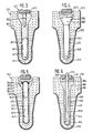
- FIG. 1 shows a partially sectioned side view of an enlarged glow plug according to the invention
- FIG. 2 shows the further enlarged, combustion chamber-side end section of the glow plug heater shown in FIG. 1, the heat sink of which remains in a solid state at all operating temperatures and one at low and medium operating temperatures 3 is the gap to the ceramic carrier forming metal core Representation of the combustion chamber end section of a glow plug heater similar to that of FIG. 2, however, the heat sink is a metal core melting at high operating temperatures
- FIG. 4 representation of the combustion chamber end section of a glow plug heater similar to that of FIG.
- FIG. 2 is a representation of the combustion chamber-side end section of a glow plug heating element similar to that according to FIG. 4, but with the metal core being designed as a heat pipe
- FIG. 6 is a representation of the combustion chamber-side end section of an operating state in the solid state, which always forms a gap with respect to the ceramic carrier Glow plug heater similar to that of Figure 4, but with an additional optoelectronic combustion chamber sensor installed in the metal core.
- the glow plug 10 shown in FIGS. 1 and 2 essentially consists of three parts: a heating element 11, a bolt-shaped connection means 12 and a tubular metal housing 13.
- the metal housing 13 has for the installation of the glow plug 10 in an internal combustion engine, not shown, on its outside a screw thread 14, a hexagon key 15 and a sealing seat 16.
- a sealing shoulder 18 In the longitudinal bore 17 of this tubular metal housing 13 there is a sealing shoulder 18 on which a sealing ring 19 rests and which is arranged facing away from the end section of the glow plug 10 on the combustion chamber side.
- the radiator 11 of this glow plug 10 is firmly and sealingly covered over part of its length by the metal housing 13.
- the heater 11 has a ceramic carrier 20, which consists of electrically insulating ceramic material or glass ceramic, but is preferably made of aluminum oxide.
- the ceramic carrier 20 has a connection-side-pointing head 21, merges into a collar 23 via a connection-side-pointing sealing shoulder 22, continues on the combustion chamber side as a collar shoulder 24 with a small diameter, and merges into the foot 26 of the ceramic carrier 20 via a combustion-chamber-side sealing shoulder 25.
- the ceramic support 20 rests with its sealing shoulder 25 on the combustion chamber side on the sealing ring 19 in the housing longitudinal bore 17, carries a sealing ring 27 on its sealing shoulder 22 on the connection side and is pressed by a flanged edge located on the connection-side end section of the metal housing 13 and pressing on the sealing ring 27 28 fixed.
- the metal housing 13 has what is known as a heat-shrinkable region 29, which is known per se (US Pat. No. 2,111,916) and ensures that the radiator 11 is installed in a sealed manner in the metal housing 13.
- the ceramic carrier 20 can also be fixed in a sealing manner in the metal housing 13 by cementing or the like.
- the ceramic carrier 20 has a longitudinal bore 30 which is open on the connection side and closed on the combustion chamber side with a base 31; the connection-side region of the ceramic carrier longitudinal bore 30, referred to as the head bore 32, goes via a frustoconical bore transition 33 into the foot having a smaller diameter bore 34 over.
- the bottom 31 of the ceramic carrier 20 preferably protrudes somewhat from the longitudinal bore 17 of the metal housing 13 on the combustion chamber side; the ceramic support head 21, on the other hand, protrudes somewhat further from the connection-side end of the metal housing 13 in the illustrated embodiment of the glow plug 10.
- the end section of the ceramic support foot 26 on the combustion chamber side is preferably protected on the combustion chamber side by a protective sleeve 35, which consists of heat-resistant material End of the metal housing 13 is fixed by welding or the like, keeps a distance from the bottom 31 of the ceramic carrier 20 and is provided with openings 36 which serve the entry or exit of unburned or burned fuel vapor-air mixtures to the radiator 11.
- the heating element 37 of this radiator 11 is - as already known from the German utility model 81 03 317 - applied in layers to the outside of the ceramic support base 26, preferably in the area of the dome-shaped ceramic support base 31, preferably consists of a platinum-rhodium alloy with ceramic component (e.g. aluminum oxide), but can also be made of another suitable, electrically conductive material.
- This heating element 3-7 is preferably applied to the base 31 of the ceramic carrier 20 by means of known thick-film technology and can be of a configuration adapted to the respective application (for example meandering or as a constriction).
- This heating element 37 is connected to connecting conductor tracks 38 and 39, which are likewise applied to the ceramic carrier 20 in thick-film technology and preferably consist of a mixture of platinum and aluminum oxide; instead of using Platinum for these conductor tracks 38 and 39 as well as for the heating element 37 can also suitable base metals such as. B. Tungsten and applied to the ceramic substrate 20 in thick-film technology.
- the first connecting conductor 38 is guided up to the sealing shoulder 25 of the ceramic carrier 20 and is in electrical connection here via the sealing ring 19 with the metal housing 13 which is electrically connected to ground.
- the second connecting conductor 39 runs all the way to the connection-side end of the ceramic support 20 and then further into the ceramic support longitudinal bore 30, namely up to the frustoconical bore transition 33.
- the heating element 37 and the connecting conductor tracks 38, 39 are covered with a protective layer 40 exclusively at their end sections (see FIG. 2); the second connecting conductor 39 is covered with this protective layer 40 at least up to the connection-side end of the ceramic carrier head 21.
- This protective layer 40 is a dense, electrically insulating, ceramic material such as. B. alumina and magnesium spinel.
- the connecting means 12 is designed as a bolt and preferably has a knurling or a thread as anchoring means 42 on its combustion chamber-side end section. While the anchoring means 42 is fixed in the glass melt flow, the connection bolt 12 has a connection thread 43 on its connection-side end section, by means of which it connects with additional connection means, not shown, is connected to a current source, also not shown, in an electrically conductive manner.
- connecting bolt 12 For axially fixing the connecting bolt 12 in the ceramic carrier longitudinal bore 30, it is provided with a collar 44 which rests on the end face 45 of the ceramic carrier 20.
- the power supply from the power source, not shown, to the heating element 37 thus takes place via the connecting bolt 12, the electrically conductive glass melt flow 41 and the second connecting conductor 39.
- landing sites can also serve as connection means, which would have to be arranged isolated from one another on the ceramic carrier head 21; the landing sites are known to be applied to the ceramic carrier head 21 using thick-film technology and can consist, for example, of platinum.
- the first connection conductor 38 can also be guided correspondingly to the ceramic support head 21.
- the connection the connection.
- Bolts 12 are omitted.
- this glow plug 10 In order to be able to use such a glow plug 10 also in the upper load range for use in internal combustion engines with spark ignition (gasoline engine, multi-fuel engine), it is according to the invention in the region of the foot bore 34 of the ceramic carrier 20 with a heat sink 46 designed so that it dissipates heat from the combustion chamber-side region of the radiator 11 in the direction of the connection-side end section of the glow plug 10, in particular at operating temperatures above approximately 850/950 C.
- this heat sink 46 is designed as a metal core which bears a substantial part of its surface on the ceramic carrier 20 above the mentioned operating temperatures, but at least partially has a gap 47 with respect to the ceramic carrier 20 below the mentioned operating temperatures.
- Such a metal core 46 consists of a material which has a solid state in all operating states of the internal combustion engine and which closes or opens the gap 47 due to its expansion or shrinkage behavior due to the effect of temperature. Suitable materials for such a metal core 46 are preferably aluminum bronze and chromium-nickel steel, which also have an increasing thermal conductivity with increasing temperature, but other materials such as e.g. B. copper and silver.
- the connection-side end face 48 of this metal core 46 lies approximately at the connection-side end of the ceramic carrier foot bore 34, but can also lie further on the connection side, for. B. extend into the bore transition 33 or even up to the combustion chamber-side section of the ceramic support head bore 32.
- the connection-side end face 48 of the metal core 46 simultaneously forms the boundary on the combustion chamber side for the electrically conductive glass melt flow 41.
- the metal core 46 has a diameter of 2.8 mm and a length of 12 mm; depending on the application, these can Dimensions vary, in particular with regard to the length of the metal core 46, which can be approximately in the range between 3 and 15 mm.
- the ceramic carrier 20 has a wall thickness of 0.5 mm in the region of its base 31, but increases in the direction of the collar shoulder 24 to approximately 3 mm. Electrically conductive glass melt flows 41 are known per se and are described, for example, in US Pat. No. 3,909,459.
- a gap 47 is present between the heat sink 46 and the foot bore 34 of the ceramic carrier 20, which gap closes in accordance with the expansion behavior of the metal core 46 as the operating temperature increases and closes above approximately 850/950 C with a considerable part of its surface creates the wall of the foot hole 34; the more the gap 47 narrows or the more parts of its surface are applied to the wall of the foot bore 34, the more heat is dissipated from the end section of the heating element 11 on the combustion chamber side to the area of the glow plug 10 on the connection side.
- the design of the gap 47 is also of major importance for the adaptation to the respective internal combustion engine; it can therefore also be advantageous if the gap 47 in the area of the ceramic carrier base 31 is larger than on the side next to the metal core 46.
- the gap 47 widens again and dissipates less heat from the ceramic carrier base 31. As a result of the mode of operation described above, the occurrence of glow ignitions in internal combustion engines with spark ignition is avoided.
- FIG 3 the combustion chamber end portion of a radiator 11/1 is shown, which differs from the radiator 11 in Figure 2 in that in the foot hole 34/1 of the associated ceramic carrier 20/1 such a heat sink 46/1 is located, which in Temperature range around 850/950 ° C melts.
- This heat sink 46/1 is preferably made of tin or silicon bronze, because these are substances which have an increasing thermal conductivity with increasing temperature; it should be mentioned that aluminum alloys or brass are also suitable for this purpose.
- the pin-like connection means 12/1 is equipped on the combustion chamber side with a pin 49/1 which dips into the connection-side end section of the heat sink 46/1.
- FIG. 4 shows the end section on the combustion chamber side of another embodiment of a radiator 11/2:
- This radiator 11/2 has a heat sink 46/2, which is always in a fixed state and a gap 47/2 for the wall of the foot bore 34 at all operating temperatures / 2 of the ceramic carrier 20/2 forms; this gap 47/2 is preferably also somewhat larger in the area of the ceramic carrier base 31/2 than to the side of the heat sink 46/2.
- the length of the heat sink 46/2 and also its gap 47/2 can be varied: However, the width of the gap 47/2 moves towards usually between 0.1 and 0.5 mm.
- Metals such as aluminum bronze, chromium-nickel steel, copper, silver and also tin bronze can also be used as materials for such heat sinks 36/2.
- a head 50/2 which preferably projects into the area of the bore transition 33/2 or even into the head bore 32/2 and thereby on the wall of the ceramic carrier 20/2 is present.
- FIG. 5 shows the section on the combustion chamber side of a further embodiment of a radiator 11/3, which differs from the radiators 11 to 11/2 described above in that it has a so-called heat pipe as heat sink 46/3, which how the heat sink 46/2 shown in Figure 4 always forms a gap 47/3 to the wall of the foot hole 34/3 of the ceramic carrier 20/3.
- heat pipes 46/3 are known per se (z. B. DE-PS 27 48 711) and have a tubular body 51/3 closed on both sides, which in its interior 52/3 partially with a heat transfer medium 53/3 such.
- B. Lithium is filled.
- the wall of the interior 52/3 is provided with a capillary structure 54/3 which is designed as grooves or in the form of a gauze layer and connects the two bottom parts of the interior 52/3 to one another.
- the heat supplied to the end section of the heat pipe 46/3 on the combustion chamber is rapidly dissipated at corresponding temperatures by means of the evaporating heat transport medium 53/3 in the direction of the connection-side area of the heat pipe 46/3 and thus into the connection-side area of the radiator 11/3.
- the evaporated heat transfer medium 53/3 condenses on the connection-side area of the interior 52/3 and is returned in the capillary structure 54/3 in the direction of the area of the heat pipe 46/3 on the combustion chamber side.
- the heat pipe 46/3 is provided at its connection-side end section with a metallic head 50/3, which is attached to the tubular body 51/3 by a brazed connection 55/3 and lies at least at the bore transition 33/3 of the ceramic carrier 20/3.
- Glow plugs with such a heat sink 46/3 are only suitable for internal combustion engines in which the glow plug is always installed approximately in a vertical position.
- the exemplary embodiment of a radiator 11/4 shown in FIG. 6 shows that heat sinks 46/4 which always remain in a solid state - as shown in FIGS. 1, 2 and 4 - can be provided with a combustion chamber sensor 55/4.
- a combustion chamber sensor 55/4 In the present example in a longitudinal bore 56/4 of the heat sink 46/4 a z. B. built of quartz glass existing optoelectronic sensor element; this optoelectronic sensor element leads on the connection side through the glass melt flow 41/4 and a central bore 57/4 of the bolt-like connection means 12/4 to an optoelectric converter (DE-OS 29 05 506), not shown, and is on the combustion chamber side with a lens-like near the bottom 31 / 4 of the ceramic support 20/4 molded thickening 53/4.
- DE-OS 29 05 506 optoelectric converter
- the head of this heat sink 46/4 is designated 50/4 and the gap between the heat sink 46/4 and the wall of the foot hole 34/4 of the ceramic carrier 20/4 bears the reference number 47/4.
- the gap 47/4 can decrease with increasing operating temperatures or increase with falling temperatures, but it can also - depending on the application - close completely at operating temperatures above 850/950 ° C.
- the central bore 57/4 leading through the connection means 12/4 is provided on the combustion chamber side with a coaxial depression 59/4, into which the glass melt flow 41/4 also penetrates.
Landscapes
- Engineering & Computer Science (AREA)
- Chemical & Material Sciences (AREA)
- Combustion & Propulsion (AREA)
- Mechanical Engineering (AREA)
- General Engineering & Computer Science (AREA)
- Combustion Methods Of Internal-Combustion Engines (AREA)
- Resistance Heating (AREA)
Abstract
Description
- Die Erfindung geht aus von einer Glühkerze für Brennkraftmaschinen nach der Gattung des Hauptanspruchs. Es ist schon eine Glühkerze mit einem Heizkörper bekannt (DE-OS 31 04 401), bei der auf einem elektrisch isolierenden, brennraumseits mit einem Boden versehenem Keramikrohr ein leiterbahnartiges Heizelement angeordnet ist; diese Glühkerze ist insbesondere für Brennkraftmaschinen ohne Fremdzündung geeignet, kann aber auch für Vielstoffmotoren mit Fremdzündung Anwendung finden. Bei der Verwendung derartiger Glühkerzen zur Zündung von Kraftstoffdampf-Luft-Gemischen im Zylinderkopf von Brennkraftmaschinen mit Fremdzündung (Ottomotor) arbeiten diese Glühkerzen im unteren und im mittleren Lastbereich ebenfalls einwandfrei, im oberen Lastbereich treten mit diesen Glühkerzen jedoch Glühzündungen auf.
- Die erfindungsgemäße Glühkerze mit den kennzeichnenden Merkmalen des Hauptanspruchs hat demgegenüber den Vorteil, daß sie auch für das Zünden von Kraftstoffdampf-Luft-Gemischen in Brennkraftmaschinen mit Fremdzündung (Ottomotor) Anwendung finden kann und dabei nicht nur im unteren und im mittleren Lastbereich einwandfrei arbeitet, sondern infolge der erfinderischen Merkmalen im oberen Lastbereich das Entstehen von Glühzündungen verhindert.
- Als weiterer Vorteil ist anzusehen, daß eine solche Glühkerze keine Hochspannungsversorgung benötigt, welche sonst bei Brennkraftmaschinen mit Fremdzündung erforderlich ist, sondern mit einer erheblich-billigeren und einfacheren Niederspannungsversorgung auskommt.
- Durch die in den Unteransprüchen aufgeführten Maßnahmen sind vorteilhafte Weiterbildungen und Verbesserungen der im Hauptanspruch angegebenen Glühkerze möglich.
- Ausführungsbeispiele der Erfindung sind in der Zeichnung dargestellt und in der nachfolgenden Beschreibung näher erläutert. Es zeigen Figur 1 eine teilgeschnittene Seitenansicht einer vergrößert dargestellten Glühkerze nach der Erfindung, Figur 2 den weiter vergrößert dargestellten, brennraumseitigen Endabschnitt des in Figur 1 gezeigten Glühkerzen-Heizkörpers, dessen Wärmesenke ein bei allen Betriebstemperaturen in festem Zustand bleibender, bei niedrigen und mittleren Betriebstemperaturen einen Spalt zum Keramikträger bildender Metallkern ist, Figur 3 die Darstellung des brennraumseitigen Endabschnitts eines Glühkerzen-Heizkörpers ähnlich dem nach Figur 2, wobei jedoch die Wärmesenke ein bei hohen Betriebstemperaturen erschmelzender Metallkern ist, Figur 4 eine Darstellung des brennraumseitigen Endabschnitts eines Glühkerzen-Heizkörpers ähnlich dem nach Figur 2, wobei jedoch die Wärmesenke ein bei allen Betriebszuständen in festem Zustand bleibender, stets einen Spalt gegenüber dem Keramikträger bildender Metallkern ist, Figur 5 eine Darstellung des brennraumseitigen Endabschnitts eines Glühkerzen-Heizkörpers ähnlich dem nach Figur 4, wobei jedoch der Metallkern als Wärmerohr ausgebildet ist und Figur 6 eine Darstellung des brennraumseitigen Endabschnitts eines Glühkerzen-Heizkörpers ähnlich dem nach Figur 4, wobei jedoch in den Metallkern zusätzlich ein optoelektronischer Brenn- - raüm-Sensor eingebaut ist.
- Die in den Figuren 1 und 2 dargestellte Glühkerze 10 besteht im wesentlichen aus drei Teilen: Einem Heizkörper 11, einem bolzenförmigen Anschlußmittel 12 und einem rohrförmigen Metallgehäuse 13.
- Das Metallgehäuse 13 hat für den Einbau der Glühkerze 10 in eine nicht dargestellte Brennkraftmaschine an seiner Außenseite ein Einschraubgewinde 14, ein Schlüsselsechskant 15 und einen Dichtsitz 16. In der Längsbohrung 17 dieses rohrförmigen Metallgehäuses 13 befindet sich ein Dichtabsatz 18, auf welchem ein Dichtring 19 aufliegt und der dem brennraumseitigen Endabschnitt der Glühkerze 10 abgewendet angeordnet ist.
- Der Heizkörper 11 dieser Glühkerze 10 wird auf einem Teil seiner Länge von dem Metallgehäuse 13 fest und abdichtend umfaßt. Der Heizkörper 11 besitzt einen Keramikträger 20, welcher aus elektrisch isolierendem Keramikmaterial oder Glaskeramik besteht, vorzugsweise jedoch aus Aluminiumoxid hergestellt ist. Der Keramikträger 20 hat einen anschlußseits weisenden Kopf 21, geht über eine anschlußseits weisende Dichtschulter 22 in einen Bund 23 über, setzt sich brennraumseits als einen kleinen Durchmesser habender Bundansatz 24 fort und geht über eine brennraumseitsweisende Dichtschulter 25 in den Fuß 26 des Keramikträgers 20 über. Der Keramikträger 20 liegt mit seiner brennraumseits weisenden Dichtschulter 25 auf dem Dichtring 19 in der Gehäuse-Längsbohrung 17 auf, trägt auf seiner anschlußseits weisenden Dichtschulter 22 einen Dichtring 27 und wird durch einen am anschlußseitigen Endabschnitt des Metallgehäuses 13 befindlichen, auf den Dichtring 27 drückenden Bördelrand 28 fixiert. Wie aus der Figur 1 ersichtlich ist, besitzt das Metallgehäuse 13 einen sogenannten Warmschrumpfbereich 29, welcher an sich bekannt ist (US-PS 2 111 916) und für einen abdichtenden Einbau des Heizkörpers 11 im Metallgehäuse 13 sorgt. Anstelle der Anwendung dieses Bördel- und Warmschrumpfprozesses kann der Keramikträger 20 aber auch durch Einkitten oder ähnliches im Metallgehäuse 13 abdichtend festgelegt werden.
- Der Keramikträger 20 besitzt eine Längsbohrung 30, welche anschlußseits offen und brennraumseits mit einem Boden 31 verschlossen ist; der als Kopfbohrung 32 bezeichnete anschlußseitige Bereich der Keramikträger-Längsbohrung 30 geht über einen kegelstumpfförmigen Bohrungsübergang 33 in die einen kleineren Durchmesser habende Fußbohrung 34 über. Der Boden 31 des Keramikträgers 20 ragt in der vorliegenden Darstellung in bevorzugter Weise brennraumseits aus der Längsbohrung 17 des Metallgehäuses 13 etwas heraus; der Keramikträger-Kopf 21 ragt dagegen bei der dargestellten Ausführungsform der Glühkerze 10 etwas weiter aus dem anschlußseitigen Ende des Metallgehäuses 13. Der brennraumseitige Endabschnitt des Keramikträger-Fußes 26 ist in bevorzugter Weise mittels einer Schutzhülse 35 geschützt, welche aus warmfestem Material besteht, am brennraumseitigen Ende des Metallgehäuses 13 durch Schweißen oder ähnliches befestigt ist, Abstand vom Boden 31 des Keramikträgers 20 hält und mit Durchbrüchen 36 versehen ist, die dem Zutritt bzw. Austritt von unverbrannten bzw. verbrannten Kraftstoffdampf-Luft-Gemischen zum Heizkörper 11 dienen.
- Das Heizelement 37 dieses Heizkörpers 11 ist - wie bereits aus der deutschen Gebrauchsmusterschrift 81 03 317 bekannt - schichtförmig auf die Außenseite des Keramikträger-Fußes 26 aufgetragen, bevorzugt im Bereich des kuppenförmigen Keramikträger-Bodens 31, besteht bevorzugt aus einer Platin-Rhodium-Legierung mit keramischem Anteil (z. B. Aluminiumoxid), kann aber auch aus einem anderen geeigneten, elektrisch-leitendem Material hergestellt sein. Dieses Heizelement 3-7 wird bevorzugt mittels bekannter Dickschichttechnik auf dem Boden 31 des Keramikträgers 20 aufgebracht und kann von dem jeweiligen Anwendungszweck angepaßter Konfiguration sein (z.B. mäanderförmig oder als Einschnürung). Dieses Heizelement 37 ist mit Anschlußleiterbahnen 38 bzw. 39 verbunden, welche ebenfalls in Dickschichtt-echnik auf den Keramikträger 20 aufgebracht sind und in bevorzugter Weise aus einer Mischung von Platin und Aluminiumoxid bestehen; anstelle der Verwendung von Platin für diese Anschlußleiterbahnen 38 und 39 wie auch für das Heizelement 37 können auch geeignete Nichtedelmetalle wie z. B. Wolfram benutzt und in Dickschichttechnik auf den Keramikträger 20 aufgetragen werden.
- Die erste Anschlußleiterbahn 38 ist bis auf die Dichtschulter 25 des Keramikträgers 20 geführt und steht hier über den Dichtring 19 mit dem elektrisch an Masse liegendem Metallgehäuse 13 in elektrischer Verbindung. Die zweite Anschlußleiterbahn 39 verläuft ganz bis zum anschlußseitigem Ende des Keramikträgers 20 und dann noch weiter in die Keramikträger-Längsbohrung 30 hinein, und zwar bis zum kegelstumpfförmigen Bohrungsübergang 33 hin. Zur elektrischen Isolation gegenüber dem Metallgehäuse 13 und auch als Schutz vor den Verbrennungsgasen und kurzschließenden Ablagerungen sind das Heizelement 37 und die Anschlußleiterbahnen 38, 39 ausschließlich ihrer Endabschnitte mit einer Schutzschicht 40 abgedeckt (siehe Figur 2); die zweite Anschlußleiterbahn 39 ist dabei zumindest bis zum anschlußseitigen Ende des Keramikträger-Kopfes 21 mit dieser Schutzschicht 40 bedeckt. Bei dieser Schutzschicht 40 handelt es sich um ein dichtes, elektrisch isolierendes, keramisches Material wie z. B. Aluminiumoxid und Magnesiumspinell.
- Der in die Längsbohrung 30 des Keramikträgers 20 hineinragende Bereich der zweiten Anschlußleiterbahn 39 steht über einen elektrisch leitfähigen, im Bereich des Bohrungsübergangs 33 und im brennraumseitigen Endabschnitt der Kopfbohrung 32 befindlichen Glasschmelzfluß 41 mit dem-brennraumseitigen Endabschnitt eines in die Keramikträger-Längsbohrung 30 hineinragenden Anschlußmittels 12 elektrisch leitend in Verbindung. Das Anschlußmittel 12 ist als Bolzen gestaltet und besitzt an seinem brennraumseitigen Endabschnitt in bevorzugter Weise eine Rändelung oder ein Gewinde als Verankerungsmittel 42. Während das Verankerungsmittel 42 im Glasschmelzfluß festgelegt ist, besitzt der Anschlußbolzen 12 an seinem anschlußseitigen Endabschnitt ein Anschlußgewinde 43, über welches er mit nicht dargestellten zusätzlichen Anschlußmitteln mit einer ebenfalls nicht dargestellten Stromquelle elektrisch leitend in Verbindung steht. Zur axialen Fixierung des Anschlußbolzens 12 in der Keramikträger-Längsbohrung 30 ist er mit einem Bund 44 versehen, welcher auf der Stirnseite 45 des Keramikträgers 20 aufliegt. Die Stromzuführung von der nicht dargestellten Stromquelle zum Heizelement 37 erfolgt also über den Anschlußbolzen 12, den elektrisch leitenden Glasschmelzfluß 41 und die zweite Anschlußleiterbahn 39.
- Anstelle der vorstehend aufgezeigten Stromzuleitung zum Heizelement 37 können als Anschlußmittel aber auch sogenannte (nicht dargestellte) Landeplätze dienen, welche auf dem Keramikträger-Kopf 21 isoliert voneinander anzuordnen wären; die Landeplätze werden bekannterweise in Dickschichttechnik auf den Keramikträger-Kopf 21 aufgetragen und können beispielsweise aus Platin bestehen. Bei Verwendung derartiger Landeplätze als Anschlußmittel kann auch die erste Anschlußleiterbahn 38 entsprechend zum Keramikträger-Kopf 21 geführt werden. Bei dieser Ausführungsform des Anschlußmittels kann der Anschluß- . bolzen 12 entfallen.
- Um eine solche Glühkerze 10 nun auch für die Verwendung in Brennkraftmaschinen mit Fremdzündung (Ottomotor, Vielstoffmotor) auch im oberen Lastbereich einsetzen zu können, ist sie erfindungsgemäß im Bereich der Fußbohrung 34 des Keramikträgers 20 mit einer Wärmesenke 46 so ausgelegt, daß sie insbesondere bei Betriebstemperaturen oberhalb von etwa 850/950 C Wärme aus dem brennraumseitigen Bereich des Heizkörpers 11 in Richtung des anschlußseitigen Endabschnitts der Glühkerze 10 ableitet. Bei dem in den Figuren 1 und 2 dargestellte Ausführungsbeispiel ist diese Wärmesenke 46 als Metallkern ausgebildet, welcher oberhalb der genannten Betriebstemperaturen mit einem erheblichen Teil seiner Oberfläche am Keramikträger 20 anliegt, jedoch unterhalb der genannten Betriebstemperaturen mindestens teilsweise einen Spalt 47 gegenüber dem Keramikträger 20 aufweist. Ein solcher Metallkern 46 besteht aus einem Material, welches bei allen vorkommenden Betriebszuständen der Brennkraftmaschine einen festen Zustand hat und aufgrund seines Ausdehnungs- bzw. Schrumpfverhaltens infolge Temperatureinwirkung den Spalt 47 schließt bzw. öffnet. Als geeignete Stoffe für einen solchen Metallkern 46 eignen sich vorzugsweise Aluminiumbronze und Chrom-Nickel-Stahl, welche mit zunehmender Temperatur auch eine zunehmende Wärmeleitfähigkeit besitzen, geeignet sind aber auch andere Stoffe wie z. B. Kupfer und Silber. Die anschlußseitige Stirnfläche 48 dieses Metallkernes 46 liegt etwa am anschlußseitigen Ende der Keramikträger-Fußbohrung 34, kann aber auch weiter anschlußseits liegen, z. B. bis in den Bohrungsübergang 33 oder sogar bis in den brennraumseitigen Abschnitt der Keramikträger-Kopfbohrung 32 reichen. Die anschlußseitige Stirnfläche 48 des Metallkernes 46 bildet gleichzeitig die brennraumseitige Begrenzung für den elektrisch leitfähigen Glasschmelzfluß 41.
- Bei einem praktischen Ausführungsbeispiel einer solchen Glühkerze 10 für Brennkraftmaschinen mit Fremdzündung hat der Metallkern 46 einen Durchmesser von 2,8 mm und eine Länge von 12 mm; je nach Anwendungsfall können diese Maße variieren, insbesondere hinsichtlich der Länge des Metallkernes 46, die etwa im Bereich zwischen 3 und 15 mm liegen kann. Der Keramikträger 20 hat im Bereich seines Bodens 31 eine Wanddicke um 0,5 mm, verstärkt sich in Richtung des Bundansatzes 24 jedoch auf etwa 3 mm. Elektrisch leitfähige Glasschmelzflüsse 41 sind an sich bekannt und beispielsweise in der US-Patentschrift 3 909 459 beschrieben.
- Bei dieser Glühkerze 10 ist zwischen der Wärmesenke 46, und der Fußbohrung 34 des Keramikträgers 20 ein Spalt 47 vorhanden, welcher sich bei zunehmenden Betriebstemperaturen entsprechend dem Ausdehnungsverhalten des Metallkerns 46 schließt und sich oberhalb von etwa 850/950 C mit einem erheblichen Teil seiner Oberfläche an die Wand der Fußbohrung 34 anlegt; je mehr sich der Spalt 47 verengt bzw. je mehr Anteile seiner Oberfläche sich an der Wand der Fußbohrung 34 anlegen, um so mehr Wärme wird aus dem brennraumseitigen Endabschnitt des Heizkörpers 11 zum anschlußseitigen Bereich der Glühkerze 10 abgeleitet. Auch die Gestaltung des Spaltes 47 hat für die Anpassung an die jeweilige Brennkraftmaschine eine wesentliche Bedeutung; es kann deshalb auch von Vorteil sein, wenn der Spalt 47 im Bereich des Keramikträger-Bodens 31 größer ist als seitlich neben dem Metallkern 46. Fallen die Betriebstemperaturen unter den Bereich von etwa 850/950°C, so erweitert sich der Spalt 47 wieder und führt weniger Wärme vom Keramikträger-Boden 31 ab. Infolge der vorstehend beschriebenen Funktionsweise wird das Entstehen von Glühzündungen in Brennkraftmaschinen mit Fremdzündung vermieden.
- In Figur 3 ist der brennraumseitige Endabschnitt eines Heizkörpers 11/1 dargestellt, welcher sich von dem Heizkörper 11 in der Figur 2 dadurch unterscheidet, daß in der Fußbohrung 34/1 des zugehörigen Keramikträgers 20/1 eine solche Wärmesenke 46/1 befindet, welche im Temperaturbereich um 850/950°C erschmilzt. Diese Wärmesenke 46/1 besteht vorzugsweise aus Zinn- oder Siliciumbronze, denn dabei handelt es sich um Stoffe, welche mit zunehmender Temperatur auch eine zunehmende Wärmeleitfähigkeit haben; es sei erwähnt, daß für diesen Zweck aber auch Aluminiumlegierungen oder Messing geeignet sind. Infolge des sich zunächst schließenden Spaltes 47/1 zwischen Wärmesenke 46/1 und Wand der Fußbohrung 34/1 des Keramikträgers 20/1 und anschließend durch das Erschmelzen der Wärmesenke 46/1 wird Wärme aus dem Bereich des Keramikträger-Bodens 31/1 in Richtung des anschlußseitigen Endabschnitts des Keramikträgers 20/1 abgeleitet und damit Glühzündungen im Vollastbereich der entsprechenden Brennkraftmaschine vermieden. Zur verbesserten Wärmeableitung ist das bolzenartige Anschlußmittel 12/1 brennraumseits mit einem Zapfen 49/1 ausgestattet, welcher in den anschlußseitigen Endabschnitt der Wärmesenke 46/1 eintaucht.
- Die Figur 4 zeigt den brennraumseitigen Endabschnitt einer anderen Ausführungsform eines Heizkörpers 11/2: Dieser Heizkörper 11/2 hat nämlich eine Wärmesenke 46/2, welche stets einen festen Zustand inne hat und bei allen Betriebstemperaturen einen Spalt 47/2 zur Wandung der Fußbohrung 34/2 des Keramikträgers 20/2 bildet; dieser Spalt 47/2 ist im Bereiche des Keramikträger-Bodens 31/2 bevorzugterweise auch etwas größer als seitlich von der Wärmesenke 46/2. Je nach Anwendungsfall kann die Länge der Wärmesenke 46/2 und auch ihr Spalt 47/2 variiert werden: Die Breite des Spaltes 47/2 bewegt sich jedoch zumeist zwischen 0,1 und 0,5 mm. Als Stoffe für derartige Wärmesenken 36/2 können ebenfalls Metalle wie Aluminiumbronze, Chrom-Nickel-Stahl, Kupfer, Silber und auch Zinnbronze Verwendung finden. Für eine sichere Fixierung einer solchen Wärmesenke 46/2 ist sie mit einem Kopf 50/2 versehen, welcher bevorzugt in den Bereich des Bohrungs- übergangs 33/2 oder sogar bis hinein in die Kopfbohrung 32/2 hineinragt und dabei an der Wandung des Keramikträgers 20/2 anliegt.
- In der Figur 5 ist der brennraumseitige Abschnitt einer weiteren Ausführungsform eines Heizkörpers 11/3 dargestellt, welcher sich von den vorstehend beschriebenen Heizkörpern 11 bis 11/2 dadurch unterscheidet, daß er als Wärmesenke 46/3 ein sogenanntes Wärmerohr (heat pipe) besitzt, welches wie die in Figur 4 dargestellte Wärmesenke 46/2 stets einen Spalt 47/3 zur Wand der Fußbohrung 34/3 des Keramikträgers 20/3 bildet. Derartige Wärmerohre 46/3 sind an sich bekannt (z. B. DE-PS 27 48 711) und haben einen beidseitig geschlossenen Rohrkörper 51/3, welcher in seinem Innenraum 52/3 teilweise mit einem Wärmetransportmedium 53/3 wie z. B. Lithium gefüllt ist. Die Wand des Innenraumes 52/3 ist dabei mit einer Kapillarstruktur 54/3 versehen, welche als Rillen oder.in Form einer Gazeschicht ausgebildet ist und die beiden Bodenteile des Innenraumes 52/3 miteinander verbindet. Die dem brennraumseitigen Endabschnitt des Wärmerohres 46/3 zugeführte Wärme wird bei entsprechenden Temperaturen mittels des verdampfenden Wärmetransportmediums 53/3 schnell in Richtung des anschlußseitigen Bereichs des Wärmerohres 46/3 und damit in den anschlußseitigen Bereich des Heizkörpers 11/3 abgeleitet. Das verdampfte Wärmetransportmedium 53/3 kondensiert am anschlußseitigen Bereich des Innenraumes 52/3 und wird in der Kapillarstruktur 54/3 in Richtung des brennraumseitigen Bereichs des Wärmerohres 46/3 zurückgeführt. - Zur sicheren Fixierung des Wärmerohres 46/3 in der Fußbohrung 34/3 des Keramikträgers 20/3 ist es an seinem anschlußseitigen Endabschnitt mit einem metallischen Kopf 50/3 versehen, welcher durch eine Hartlötverbindung 55/3 an den Rohrkörper 51/3 angebracht ist und sich zumindest am Bohrungsübergang 33/3 des Keramikträgers 20/3 anlegt. Glühkerzen mit derartiger Wärmesenke 46/3 sind jedoch nur für solche Brennkraftmaschinen geeignet, bei denen die Glühkerze stets annähernd in senkrechter Lage eingebaut ist.
- Das in Figur 6 dargestellte Ausführungsbeispiel eines Heizkörpers 11/4 zeigt, daß stets in festem Zustand bleibende Wärmesenken 46/4 - wie sie in den Figuren 1, 2 und 4 dargestellt sind - mit einem Brennraumsensor 55/4 versehen werden können. Im vorliegenden Beispiel ist in eine Längsbohrung 56/4 der Wärmesenke 46/4 ein z. B. aus Quarzglas bestehendes optoelektronisches Sensorelement eingebaut; dieses optoelektronische Sensorelement führt anschlußseits durch den Glasschmelzfluß 41/4 und eine Zentralbohrung 57/4 des bolzenartigen Anschlußmittels 12/4 zu einem nicht dargestellten optoelektrischem Wandler (DE-OS 29 05 506) und ist brennraumseits mit einer linsenartigen, in der Nähe des Bodens 31/4 des Keramikträgers 20/4 angeformten Verdickung 53/4 versehen. Anstelle eines derartigen optoelektronischen Sensors 55/4 können aber auch andere den Betriebstemperaturen widerstehende Sensorelemente Verwendung finden, z. B. Temperatursensoren. - Der Kopf dieser Wärmesenke 46/4 ist mit 50/4 bezeichnet und der zwischen der Wärmesenke 46/4 und der Wand der Fußbohrung 34/4 des Keramikträgers 20/4 befindliche Spalt trägt das Bezugszeichen 47/4. Der Spalt 47/4 kann sich bei zunehmenden Betriebstemperaturen verringern bzw. bei sinkenden Temperaturen vergrößern, er kann sich aber auch - je nach Anwendungsfall - bei Betriebstemperaturen oberhalb von 850/950°C vollständig schließen. Zur Verbesserung der Abdichtung zwischen dem Anschlußmittel 12/4 und dem Sensor 55/4 ist die durch das Anschlußmittel 12/4 führende Zentralbohrung 57/4 brennraumseits mit einer koaxialen Einsenkung 59/4 versehen, in welche der Glasschmelzfluß 41/4 mit eindringt.
- Es hat sich gezeigt, daß alle vorstehend beschriebenen Ausführungsformen die Aufgabe der vorliegenden Erfindung zu lösen vermögen, wobei jede dieser Ausführungsformen gemäß den Figuren 1 bis 6 dem jeweiligen Anwendungszweck zuzuordnen sind.
Claims (9)
Applications Claiming Priority (2)
| Application Number | Priority Date | Filing Date | Title |
|---|---|---|---|
| DE19823237922 DE3237922A1 (de) | 1982-10-13 | 1982-10-13 | Gluehkerze fuer brennkraftmaschinen mit fremdzuendung |
| DE3237922 | 1982-10-13 |
Publications (2)
| Publication Number | Publication Date |
|---|---|
| EP0106232A1 true EP0106232A1 (de) | 1984-04-25 |
| EP0106232B1 EP0106232B1 (de) | 1986-06-18 |
Family
ID=6175603
Family Applications (1)
| Application Number | Title | Priority Date | Filing Date |
|---|---|---|---|
| EP83109726A Expired EP0106232B1 (de) | 1982-10-13 | 1983-09-29 | Glühkerze für Brennkraftmaschinen mit Fremdzündung |
Country Status (3)
| Country | Link |
|---|---|
| EP (1) | EP0106232B1 (de) |
| DE (2) | DE3237922A1 (de) |
| ES (1) | ES526443A0 (de) |
Cited By (4)
| Publication number | Priority date | Publication date | Assignee | Title |
|---|---|---|---|---|
| EP0194535A3 (de) * | 1985-03-15 | 1988-01-07 | Allied Corporation | Glühkerze mit einem schichtförmigen Heizwiderstand aus metallischen Siliziden |
| WO1997004974A1 (de) * | 1995-07-29 | 1997-02-13 | Firma J. Eberspächer | Einrichtung zum erzeugen und zünden eines brennstoffdampf-luft-gemisches |
| DE10228077A1 (de) * | 2002-06-20 | 2004-01-08 | Friedrich-Schiller-Universität Jena | Verfahren zur Herstellung einer mechanisch stabilen und elektrisch leitfähigen Verbindung zwischen einem metallischen Aufnahmeelement und einem vorzugsweise stiftförmigen keramischen Element, insbesondere bei Glühkerzen für Dieselmotoren |
| WO2006000489A1 (de) * | 2004-06-26 | 2006-01-05 | Robert Bosch Gmbh | Glühstiftkerze mit einem mit einer schutzschicht überzogenen glühstift |
Citations (3)
| Publication number | Priority date | Publication date | Assignee | Title |
|---|---|---|---|---|
| AT69738B (de) * | 1913-02-27 | 1915-08-25 | Pohl & Soehne Fa E | Zündvorrichtung für Verbrennungskraftmaschinen. |
| DE2900984A1 (de) * | 1979-01-12 | 1980-07-17 | Heraeus Gmbh W C | Gluehkerze fuer dieselmotoren |
| DE3146653A1 (de) * | 1981-02-07 | 1982-10-14 | Robert Bosch Gmbh, 7000 Stuttgart | Gluehkerze fuer brennkraftmaschinen |
Family Cites Families (2)
| Publication number | Priority date | Publication date | Assignee | Title |
|---|---|---|---|---|
| NL7612360A (nl) * | 1976-11-08 | 1978-05-10 | Philips Nv | Warmtepijp. |
| US4418661A (en) * | 1981-02-07 | 1983-12-06 | Robert Bosch Gmbh | Glow plug, particularly for diesel engine |
-
1982
- 1982-10-13 DE DE19823237922 patent/DE3237922A1/de not_active Withdrawn
-
1983
- 1983-09-29 EP EP83109726A patent/EP0106232B1/de not_active Expired
- 1983-09-29 DE DE8383109726T patent/DE3364202D1/de not_active Expired
- 1983-10-13 ES ES526443A patent/ES526443A0/es active Granted
Patent Citations (3)
| Publication number | Priority date | Publication date | Assignee | Title |
|---|---|---|---|---|
| AT69738B (de) * | 1913-02-27 | 1915-08-25 | Pohl & Soehne Fa E | Zündvorrichtung für Verbrennungskraftmaschinen. |
| DE2900984A1 (de) * | 1979-01-12 | 1980-07-17 | Heraeus Gmbh W C | Gluehkerze fuer dieselmotoren |
| DE3146653A1 (de) * | 1981-02-07 | 1982-10-14 | Robert Bosch Gmbh, 7000 Stuttgart | Gluehkerze fuer brennkraftmaschinen |
Cited By (4)
| Publication number | Priority date | Publication date | Assignee | Title |
|---|---|---|---|---|
| EP0194535A3 (de) * | 1985-03-15 | 1988-01-07 | Allied Corporation | Glühkerze mit einem schichtförmigen Heizwiderstand aus metallischen Siliziden |
| WO1997004974A1 (de) * | 1995-07-29 | 1997-02-13 | Firma J. Eberspächer | Einrichtung zum erzeugen und zünden eines brennstoffdampf-luft-gemisches |
| DE10228077A1 (de) * | 2002-06-20 | 2004-01-08 | Friedrich-Schiller-Universität Jena | Verfahren zur Herstellung einer mechanisch stabilen und elektrisch leitfähigen Verbindung zwischen einem metallischen Aufnahmeelement und einem vorzugsweise stiftförmigen keramischen Element, insbesondere bei Glühkerzen für Dieselmotoren |
| WO2006000489A1 (de) * | 2004-06-26 | 2006-01-05 | Robert Bosch Gmbh | Glühstiftkerze mit einem mit einer schutzschicht überzogenen glühstift |
Also Published As
| Publication number | Publication date |
|---|---|
| ES8405920A1 (es) | 1984-06-16 |
| ES526443A0 (es) | 1984-06-16 |
| DE3364202D1 (en) | 1986-07-24 |
| DE3237922A1 (de) | 1984-04-19 |
| EP0106232B1 (de) | 1986-06-18 |
Similar Documents
| Publication | Publication Date | Title |
|---|---|---|
| DE102012102009B4 (de) | Kammerdeckel für Vorkammer-Zündkerzen und Zündkerzen mit einem solchen Kammerdeckel | |
| DE68920725T2 (de) | Temperaturregelung von zündkerzen. | |
| EP0049372B1 (de) | Zündkerze für Brennkraftmaschinen | |
| DE3217951A1 (de) | Zuendkerze fuer brennkraftmaschinen | |
| DE2857574C2 (de) | Zündkerze | |
| DE69400394T2 (de) | Zündkerze mit Heizvorrichtung | |
| EP0238520B1 (de) | Zündkerze mit gleitfunkenstrecke | |
| DE102018206784A1 (de) | Vorkammer-Zündkerze | |
| EP0078954B1 (de) | Zündkerze für Brennkraftmaschinen | |
| DE3033769A1 (de) | Elektrodenbaugruppe | |
| DE69932685T2 (de) | Glühsensor - keramische flache Platte | |
| EP0226595B1 (de) | Zündkerze für brennkraftmaschinen | |
| DE69935641T2 (de) | Glühensensor- und - Motorteilkombination | |
| DE3415823C2 (de) | Vorkammer einer Brennkraftmaschine | |
| EP0101547B1 (de) | Hochspannungszündkerze | |
| DE4431143A1 (de) | Zündkerze für eine Brennkraftmaschine | |
| EP0106232A1 (de) | Glühkerze für Brennkraftmaschinen mit Fremdzündung | |
| DE3318458C2 (de) | ||
| DE3146653C2 (de) | Glühkerze für Brennkraftmaschinen | |
| EP1295067B1 (de) | Glühstiftkerze | |
| DE19932220A1 (de) | Zündkerze mit niedriger Zündtemperatur | |
| DE10156949B4 (de) | Zündkerze | |
| DE2263082A1 (de) | Zuendkerze | |
| EP0591250B1 (de) | Zündkerze zum zünden von kraftstoff-luft-gemischen | |
| DE1476321C (de) | Zündkerze |
Legal Events
| Date | Code | Title | Description |
|---|---|---|---|
| PUAI | Public reference made under article 153(3) epc to a published international application that has entered the european phase |
Free format text: ORIGINAL CODE: 0009012 |
|
| 17P | Request for examination filed |
Effective date: 19830929 |
|
| AK | Designated contracting states |
Designated state(s): DE FR GB IT SE |
|
| GRAA | (expected) grant |
Free format text: ORIGINAL CODE: 0009210 |
|
| AK | Designated contracting states |
Kind code of ref document: B1 Designated state(s): DE FR GB IT SE |
|
| REF | Corresponds to: |
Ref document number: 3364202 Country of ref document: DE Date of ref document: 19860724 |
|
| ET | Fr: translation filed | ||
| ITF | It: translation for a ep patent filed | ||
| PLBE | No opposition filed within time limit |
Free format text: ORIGINAL CODE: 0009261 |
|
| STAA | Information on the status of an ep patent application or granted ep patent |
Free format text: STATUS: NO OPPOSITION FILED WITHIN TIME LIMIT |
|
| 26N | No opposition filed | ||
| PGFP | Annual fee paid to national office [announced via postgrant information from national office to epo] |
Ref country code: SE Payment date: 19910816 Year of fee payment: 9 |
|
| PGFP | Annual fee paid to national office [announced via postgrant information from national office to epo] |
Ref country code: GB Payment date: 19910918 Year of fee payment: 9 |
|
| ITTA | It: last paid annual fee | ||
| PGFP | Annual fee paid to national office [announced via postgrant information from national office to epo] |
Ref country code: FR Payment date: 19910930 Year of fee payment: 9 |
|
| PGFP | Annual fee paid to national office [announced via postgrant information from national office to epo] |
Ref country code: DE Payment date: 19911125 Year of fee payment: 9 |
|
| PG25 | Lapsed in a contracting state [announced via postgrant information from national office to epo] |
Ref country code: GB Effective date: 19920929 |
|
| PG25 | Lapsed in a contracting state [announced via postgrant information from national office to epo] |
Ref country code: SE Effective date: 19920930 |
|
| GBPC | Gb: european patent ceased through non-payment of renewal fee |
Effective date: 19920929 |
|
| PG25 | Lapsed in a contracting state [announced via postgrant information from national office to epo] |
Ref country code: FR Effective date: 19930528 |
|
| PG25 | Lapsed in a contracting state [announced via postgrant information from national office to epo] |
Ref country code: DE Effective date: 19930602 |
|
| REG | Reference to a national code |
Ref country code: FR Ref legal event code: ST |
|
| EUG | Se: european patent has lapsed |
Ref document number: 83109726.6 Effective date: 19930406 |