EP0106232A1 - Bougie à incandescence pour moteurs à combustion interne avec allumage externe - Google Patents
Bougie à incandescence pour moteurs à combustion interne avec allumage externe Download PDFInfo
- Publication number
- EP0106232A1 EP0106232A1 EP83109726A EP83109726A EP0106232A1 EP 0106232 A1 EP0106232 A1 EP 0106232A1 EP 83109726 A EP83109726 A EP 83109726A EP 83109726 A EP83109726 A EP 83109726A EP 0106232 A1 EP0106232 A1 EP 0106232A1
- Authority
- EP
- European Patent Office
- Prior art keywords
- ceramic carrier
- glow plug
- heat sink
- metal core
- combustion chamber
- Prior art date
- Legal status (The legal status is an assumption and is not a legal conclusion. Google has not performed a legal analysis and makes no representation as to the accuracy of the status listed.)
- Granted
Links
- 238000002485 combustion reaction Methods 0.000 title claims abstract description 54
- 239000000919 ceramic Substances 0.000 claims abstract description 65
- 229910052751 metal Inorganic materials 0.000 claims abstract description 37
- 239000002184 metal Substances 0.000 claims abstract description 37
- 239000004020 conductor Substances 0.000 claims abstract description 18
- 238000010438 heat treatment Methods 0.000 claims abstract description 14
- 239000011241 protective layer Substances 0.000 claims abstract description 5
- 229910000906 Bronze Inorganic materials 0.000 claims description 6
- 239000010974 bronze Substances 0.000 claims description 6
- KUNSUQLRTQLHQQ-UHFFFAOYSA-N copper tin Chemical compound [Cu].[Sn] KUNSUQLRTQLHQQ-UHFFFAOYSA-N 0.000 claims description 6
- 239000000463 material Substances 0.000 claims description 6
- 230000005693 optoelectronics Effects 0.000 claims description 5
- 239000007787 solid Substances 0.000 claims description 5
- 229910000831 Steel Inorganic materials 0.000 claims description 3
- ATJFFYVFTNAWJD-UHFFFAOYSA-N Tin Chemical compound [Sn] ATJFFYVFTNAWJD-UHFFFAOYSA-N 0.000 claims description 3
- 229910052782 aluminium Inorganic materials 0.000 claims description 3
- XAGFODPZIPBFFR-UHFFFAOYSA-N aluminium Chemical compound [Al] XAGFODPZIPBFFR-UHFFFAOYSA-N 0.000 claims description 3
- VNNRSPGTAMTISX-UHFFFAOYSA-N chromium nickel Chemical compound [Cr].[Ni] VNNRSPGTAMTISX-UHFFFAOYSA-N 0.000 claims description 3
- 229910052709 silver Inorganic materials 0.000 claims description 3
- 239000004332 silver Substances 0.000 claims description 3
- 239000010959 steel Substances 0.000 claims description 3
- 229910000838 Al alloy Inorganic materials 0.000 claims description 2
- 229910001369 Brass Inorganic materials 0.000 claims description 2
- RYGMFSIKBFXOCR-UHFFFAOYSA-N Copper Chemical compound [Cu] RYGMFSIKBFXOCR-UHFFFAOYSA-N 0.000 claims description 2
- XUIMIQQOPSSXEZ-UHFFFAOYSA-N Silicon Chemical compound [Si] XUIMIQQOPSSXEZ-UHFFFAOYSA-N 0.000 claims description 2
- 239000010951 brass Substances 0.000 claims description 2
- 229910052802 copper Inorganic materials 0.000 claims description 2
- 239000010949 copper Substances 0.000 claims description 2
- 239000000155 melt Substances 0.000 claims description 2
- 229910052710 silicon Inorganic materials 0.000 claims description 2
- 239000010703 silicon Substances 0.000 claims description 2
- 230000002277 temperature effect Effects 0.000 abstract 1
- 238000007789 sealing Methods 0.000 description 13
- 239000000156 glass melt Substances 0.000 description 7
- BASFCYQUMIYNBI-UHFFFAOYSA-N platinum Chemical compound [Pt] BASFCYQUMIYNBI-UHFFFAOYSA-N 0.000 description 6
- 230000007704 transition Effects 0.000 description 6
- 239000000446 fuel Substances 0.000 description 5
- 238000005516 engineering process Methods 0.000 description 4
- 239000000203 mixture Substances 0.000 description 4
- 230000008901 benefit Effects 0.000 description 3
- 239000002609 medium Substances 0.000 description 3
- TWNQGVIAIRXVLR-UHFFFAOYSA-N oxo(oxoalumanyloxy)alumane Chemical compound O=[Al]O[Al]=O TWNQGVIAIRXVLR-UHFFFAOYSA-N 0.000 description 3
- 229910052697 platinum Inorganic materials 0.000 description 3
- 238000004873 anchoring Methods 0.000 description 2
- 229910010293 ceramic material Inorganic materials 0.000 description 2
- 239000010410 layer Substances 0.000 description 2
- 238000002844 melting Methods 0.000 description 2
- 230000008018 melting Effects 0.000 description 2
- WHXSMMKQMYFTQS-UHFFFAOYSA-N Lithium Chemical compound [Li] WHXSMMKQMYFTQS-UHFFFAOYSA-N 0.000 description 1
- 241000530268 Lycaena heteronea Species 0.000 description 1
- FYYHWMGAXLPEAU-UHFFFAOYSA-N Magnesium Chemical compound [Mg] FYYHWMGAXLPEAU-UHFFFAOYSA-N 0.000 description 1
- 229910000629 Rh alloy Inorganic materials 0.000 description 1
- VYPSYNLAJGMNEJ-UHFFFAOYSA-N Silicium dioxide Chemical compound O=[Si]=O VYPSYNLAJGMNEJ-UHFFFAOYSA-N 0.000 description 1
- 230000006978 adaptation Effects 0.000 description 1
- PNEYBMLMFCGWSK-UHFFFAOYSA-N aluminium oxide Inorganic materials [O-2].[O-2].[O-2].[Al+3].[Al+3] PNEYBMLMFCGWSK-UHFFFAOYSA-N 0.000 description 1
- 239000010953 base metal Substances 0.000 description 1
- 239000000567 combustion gas Substances 0.000 description 1
- 238000011161 development Methods 0.000 description 1
- 230000018109 developmental process Effects 0.000 description 1
- 230000000694 effects Effects 0.000 description 1
- 238000010292 electrical insulation Methods 0.000 description 1
- 238000001704 evaporation Methods 0.000 description 1
- 239000002241 glass-ceramic Substances 0.000 description 1
- 230000017525 heat dissipation Effects 0.000 description 1
- 239000003779 heat-resistant material Substances 0.000 description 1
- 238000009434 installation Methods 0.000 description 1
- 229910052744 lithium Inorganic materials 0.000 description 1
- 229910052749 magnesium Inorganic materials 0.000 description 1
- 239000011777 magnesium Substances 0.000 description 1
- 150000002739 metals Chemical class 0.000 description 1
- 238000000034 method Methods 0.000 description 1
- PXXKQOPKNFECSZ-UHFFFAOYSA-N platinum rhodium Chemical compound [Rh].[Pt] PXXKQOPKNFECSZ-UHFFFAOYSA-N 0.000 description 1
- 238000003825 pressing Methods 0.000 description 1
- 230000008569 process Effects 0.000 description 1
- 230000001681 protective effect Effects 0.000 description 1
- 239000011029 spinel Substances 0.000 description 1
- 229910052596 spinel Inorganic materials 0.000 description 1
- 239000000126 substance Substances 0.000 description 1
- 239000000758 substrate Substances 0.000 description 1
- 230000008719 thickening Effects 0.000 description 1
- 239000006163 transport media Substances 0.000 description 1
- WFKWXMTUELFFGS-UHFFFAOYSA-N tungsten Chemical compound [W] WFKWXMTUELFFGS-UHFFFAOYSA-N 0.000 description 1
- 229910052721 tungsten Inorganic materials 0.000 description 1
- 239000010937 tungsten Substances 0.000 description 1
- 238000003466 welding Methods 0.000 description 1
Images

Classifications
-
- F—MECHANICAL ENGINEERING; LIGHTING; HEATING; WEAPONS; BLASTING
- F23—COMBUSTION APPARATUS; COMBUSTION PROCESSES
- F23Q—IGNITION; EXTINGUISHING-DEVICES
- F23Q7/00—Incandescent ignition; Igniters using electrically-produced heat, e.g. lighters for cigarettes; Electrically-heated glowing plugs
- F23Q7/001—Glowing plugs for internal-combustion engines
Definitions
- the invention relates to a glow plug for internal combustion engines according to the preamble of the main claim.
- a glow plug with a radiator is already known (DE-OS 31 04 401), in which a conductor track-type heating element is arranged on an electrically insulating ceramic tube provided with a bottom on the combustion chamber side;
- This glow plug is particularly suitable for internal combustion engines without spark ignition, but can also be used for multi-fuel engines with spark ignition.
- these glow plugs When using such glow plugs for the ignition of fuel vapor-air mixtures in the cylinder head of internal combustion engines with spark ignition (gasoline engine), these glow plugs also work flawlessly in the lower and middle load range, but glow ignitions occur with these glow plugs in the upper load range.
- the glow plug according to the invention with the characterizing features of the main claim has the advantage that it can also be used for the ignition of fuel vapor-air mixtures in internal combustion engines with spark ignition (gasoline engine) and not only works properly in the lower and middle load range, but also due to the inventive features in the upper load range prevents the occurrence of glow ignition.
- FIG. 1 shows a partially sectioned side view of an enlarged glow plug according to the invention
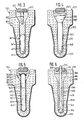
- FIG. 2 shows the further enlarged, combustion chamber-side end section of the glow plug heater shown in FIG. 1, the heat sink of which remains in a solid state at all operating temperatures and one at low and medium operating temperatures 3 is the gap to the ceramic carrier forming metal core Representation of the combustion chamber end section of a glow plug heater similar to that of FIG. 2, however, the heat sink is a metal core melting at high operating temperatures
- FIG. 4 representation of the combustion chamber end section of a glow plug heater similar to that of FIG.
- FIG. 2 is a representation of the combustion chamber-side end section of a glow plug heating element similar to that according to FIG. 4, but with the metal core being designed as a heat pipe
- FIG. 6 is a representation of the combustion chamber-side end section of an operating state in the solid state, which always forms a gap with respect to the ceramic carrier Glow plug heater similar to that of Figure 4, but with an additional optoelectronic combustion chamber sensor installed in the metal core.
- the glow plug 10 shown in FIGS. 1 and 2 essentially consists of three parts: a heating element 11, a bolt-shaped connection means 12 and a tubular metal housing 13.
- the metal housing 13 has for the installation of the glow plug 10 in an internal combustion engine, not shown, on its outside a screw thread 14, a hexagon key 15 and a sealing seat 16.
- a sealing shoulder 18 In the longitudinal bore 17 of this tubular metal housing 13 there is a sealing shoulder 18 on which a sealing ring 19 rests and which is arranged facing away from the end section of the glow plug 10 on the combustion chamber side.
- the radiator 11 of this glow plug 10 is firmly and sealingly covered over part of its length by the metal housing 13.
- the heater 11 has a ceramic carrier 20, which consists of electrically insulating ceramic material or glass ceramic, but is preferably made of aluminum oxide.
- the ceramic carrier 20 has a connection-side-pointing head 21, merges into a collar 23 via a connection-side-pointing sealing shoulder 22, continues on the combustion chamber side as a collar shoulder 24 with a small diameter, and merges into the foot 26 of the ceramic carrier 20 via a combustion-chamber-side sealing shoulder 25.
- the ceramic support 20 rests with its sealing shoulder 25 on the combustion chamber side on the sealing ring 19 in the housing longitudinal bore 17, carries a sealing ring 27 on its sealing shoulder 22 on the connection side and is pressed by a flanged edge located on the connection-side end section of the metal housing 13 and pressing on the sealing ring 27 28 fixed.
- the metal housing 13 has what is known as a heat-shrinkable region 29, which is known per se (US Pat. No. 2,111,916) and ensures that the radiator 11 is installed in a sealed manner in the metal housing 13.
- the ceramic carrier 20 can also be fixed in a sealing manner in the metal housing 13 by cementing or the like.
- the ceramic carrier 20 has a longitudinal bore 30 which is open on the connection side and closed on the combustion chamber side with a base 31; the connection-side region of the ceramic carrier longitudinal bore 30, referred to as the head bore 32, goes via a frustoconical bore transition 33 into the foot having a smaller diameter bore 34 over.
- the bottom 31 of the ceramic carrier 20 preferably protrudes somewhat from the longitudinal bore 17 of the metal housing 13 on the combustion chamber side; the ceramic support head 21, on the other hand, protrudes somewhat further from the connection-side end of the metal housing 13 in the illustrated embodiment of the glow plug 10.
- the end section of the ceramic support foot 26 on the combustion chamber side is preferably protected on the combustion chamber side by a protective sleeve 35, which consists of heat-resistant material End of the metal housing 13 is fixed by welding or the like, keeps a distance from the bottom 31 of the ceramic carrier 20 and is provided with openings 36 which serve the entry or exit of unburned or burned fuel vapor-air mixtures to the radiator 11.
- the heating element 37 of this radiator 11 is - as already known from the German utility model 81 03 317 - applied in layers to the outside of the ceramic support base 26, preferably in the area of the dome-shaped ceramic support base 31, preferably consists of a platinum-rhodium alloy with ceramic component (e.g. aluminum oxide), but can also be made of another suitable, electrically conductive material.
- This heating element 3-7 is preferably applied to the base 31 of the ceramic carrier 20 by means of known thick-film technology and can be of a configuration adapted to the respective application (for example meandering or as a constriction).
- This heating element 37 is connected to connecting conductor tracks 38 and 39, which are likewise applied to the ceramic carrier 20 in thick-film technology and preferably consist of a mixture of platinum and aluminum oxide; instead of using Platinum for these conductor tracks 38 and 39 as well as for the heating element 37 can also suitable base metals such as. B. Tungsten and applied to the ceramic substrate 20 in thick-film technology.
- the first connecting conductor 38 is guided up to the sealing shoulder 25 of the ceramic carrier 20 and is in electrical connection here via the sealing ring 19 with the metal housing 13 which is electrically connected to ground.
- the second connecting conductor 39 runs all the way to the connection-side end of the ceramic support 20 and then further into the ceramic support longitudinal bore 30, namely up to the frustoconical bore transition 33.
- the heating element 37 and the connecting conductor tracks 38, 39 are covered with a protective layer 40 exclusively at their end sections (see FIG. 2); the second connecting conductor 39 is covered with this protective layer 40 at least up to the connection-side end of the ceramic carrier head 21.
- This protective layer 40 is a dense, electrically insulating, ceramic material such as. B. alumina and magnesium spinel.
- the connecting means 12 is designed as a bolt and preferably has a knurling or a thread as anchoring means 42 on its combustion chamber-side end section. While the anchoring means 42 is fixed in the glass melt flow, the connection bolt 12 has a connection thread 43 on its connection-side end section, by means of which it connects with additional connection means, not shown, is connected to a current source, also not shown, in an electrically conductive manner.
- connecting bolt 12 For axially fixing the connecting bolt 12 in the ceramic carrier longitudinal bore 30, it is provided with a collar 44 which rests on the end face 45 of the ceramic carrier 20.
- the power supply from the power source, not shown, to the heating element 37 thus takes place via the connecting bolt 12, the electrically conductive glass melt flow 41 and the second connecting conductor 39.
- landing sites can also serve as connection means, which would have to be arranged isolated from one another on the ceramic carrier head 21; the landing sites are known to be applied to the ceramic carrier head 21 using thick-film technology and can consist, for example, of platinum.
- the first connection conductor 38 can also be guided correspondingly to the ceramic support head 21.
- the connection the connection.
- Bolts 12 are omitted.
- this glow plug 10 In order to be able to use such a glow plug 10 also in the upper load range for use in internal combustion engines with spark ignition (gasoline engine, multi-fuel engine), it is according to the invention in the region of the foot bore 34 of the ceramic carrier 20 with a heat sink 46 designed so that it dissipates heat from the combustion chamber-side region of the radiator 11 in the direction of the connection-side end section of the glow plug 10, in particular at operating temperatures above approximately 850/950 C.
- this heat sink 46 is designed as a metal core which bears a substantial part of its surface on the ceramic carrier 20 above the mentioned operating temperatures, but at least partially has a gap 47 with respect to the ceramic carrier 20 below the mentioned operating temperatures.
- Such a metal core 46 consists of a material which has a solid state in all operating states of the internal combustion engine and which closes or opens the gap 47 due to its expansion or shrinkage behavior due to the effect of temperature. Suitable materials for such a metal core 46 are preferably aluminum bronze and chromium-nickel steel, which also have an increasing thermal conductivity with increasing temperature, but other materials such as e.g. B. copper and silver.
- the connection-side end face 48 of this metal core 46 lies approximately at the connection-side end of the ceramic carrier foot bore 34, but can also lie further on the connection side, for. B. extend into the bore transition 33 or even up to the combustion chamber-side section of the ceramic support head bore 32.
- the connection-side end face 48 of the metal core 46 simultaneously forms the boundary on the combustion chamber side for the electrically conductive glass melt flow 41.
- the metal core 46 has a diameter of 2.8 mm and a length of 12 mm; depending on the application, these can Dimensions vary, in particular with regard to the length of the metal core 46, which can be approximately in the range between 3 and 15 mm.
- the ceramic carrier 20 has a wall thickness of 0.5 mm in the region of its base 31, but increases in the direction of the collar shoulder 24 to approximately 3 mm. Electrically conductive glass melt flows 41 are known per se and are described, for example, in US Pat. No. 3,909,459.
- a gap 47 is present between the heat sink 46 and the foot bore 34 of the ceramic carrier 20, which gap closes in accordance with the expansion behavior of the metal core 46 as the operating temperature increases and closes above approximately 850/950 C with a considerable part of its surface creates the wall of the foot hole 34; the more the gap 47 narrows or the more parts of its surface are applied to the wall of the foot bore 34, the more heat is dissipated from the end section of the heating element 11 on the combustion chamber side to the area of the glow plug 10 on the connection side.
- the design of the gap 47 is also of major importance for the adaptation to the respective internal combustion engine; it can therefore also be advantageous if the gap 47 in the area of the ceramic carrier base 31 is larger than on the side next to the metal core 46.
- the gap 47 widens again and dissipates less heat from the ceramic carrier base 31. As a result of the mode of operation described above, the occurrence of glow ignitions in internal combustion engines with spark ignition is avoided.
- FIG 3 the combustion chamber end portion of a radiator 11/1 is shown, which differs from the radiator 11 in Figure 2 in that in the foot hole 34/1 of the associated ceramic carrier 20/1 such a heat sink 46/1 is located, which in Temperature range around 850/950 ° C melts.
- This heat sink 46/1 is preferably made of tin or silicon bronze, because these are substances which have an increasing thermal conductivity with increasing temperature; it should be mentioned that aluminum alloys or brass are also suitable for this purpose.
- the pin-like connection means 12/1 is equipped on the combustion chamber side with a pin 49/1 which dips into the connection-side end section of the heat sink 46/1.
- FIG. 4 shows the end section on the combustion chamber side of another embodiment of a radiator 11/2:
- This radiator 11/2 has a heat sink 46/2, which is always in a fixed state and a gap 47/2 for the wall of the foot bore 34 at all operating temperatures / 2 of the ceramic carrier 20/2 forms; this gap 47/2 is preferably also somewhat larger in the area of the ceramic carrier base 31/2 than to the side of the heat sink 46/2.
- the length of the heat sink 46/2 and also its gap 47/2 can be varied: However, the width of the gap 47/2 moves towards usually between 0.1 and 0.5 mm.
- Metals such as aluminum bronze, chromium-nickel steel, copper, silver and also tin bronze can also be used as materials for such heat sinks 36/2.
- a head 50/2 which preferably projects into the area of the bore transition 33/2 or even into the head bore 32/2 and thereby on the wall of the ceramic carrier 20/2 is present.
- FIG. 5 shows the section on the combustion chamber side of a further embodiment of a radiator 11/3, which differs from the radiators 11 to 11/2 described above in that it has a so-called heat pipe as heat sink 46/3, which how the heat sink 46/2 shown in Figure 4 always forms a gap 47/3 to the wall of the foot hole 34/3 of the ceramic carrier 20/3.
- heat pipes 46/3 are known per se (z. B. DE-PS 27 48 711) and have a tubular body 51/3 closed on both sides, which in its interior 52/3 partially with a heat transfer medium 53/3 such.
- B. Lithium is filled.
- the wall of the interior 52/3 is provided with a capillary structure 54/3 which is designed as grooves or in the form of a gauze layer and connects the two bottom parts of the interior 52/3 to one another.
- the heat supplied to the end section of the heat pipe 46/3 on the combustion chamber is rapidly dissipated at corresponding temperatures by means of the evaporating heat transport medium 53/3 in the direction of the connection-side area of the heat pipe 46/3 and thus into the connection-side area of the radiator 11/3.
- the evaporated heat transfer medium 53/3 condenses on the connection-side area of the interior 52/3 and is returned in the capillary structure 54/3 in the direction of the area of the heat pipe 46/3 on the combustion chamber side.
- the heat pipe 46/3 is provided at its connection-side end section with a metallic head 50/3, which is attached to the tubular body 51/3 by a brazed connection 55/3 and lies at least at the bore transition 33/3 of the ceramic carrier 20/3.
- Glow plugs with such a heat sink 46/3 are only suitable for internal combustion engines in which the glow plug is always installed approximately in a vertical position.
- the exemplary embodiment of a radiator 11/4 shown in FIG. 6 shows that heat sinks 46/4 which always remain in a solid state - as shown in FIGS. 1, 2 and 4 - can be provided with a combustion chamber sensor 55/4.
- a combustion chamber sensor 55/4 In the present example in a longitudinal bore 56/4 of the heat sink 46/4 a z. B. built of quartz glass existing optoelectronic sensor element; this optoelectronic sensor element leads on the connection side through the glass melt flow 41/4 and a central bore 57/4 of the bolt-like connection means 12/4 to an optoelectric converter (DE-OS 29 05 506), not shown, and is on the combustion chamber side with a lens-like near the bottom 31 / 4 of the ceramic support 20/4 molded thickening 53/4.
- DE-OS 29 05 506 optoelectric converter
- the head of this heat sink 46/4 is designated 50/4 and the gap between the heat sink 46/4 and the wall of the foot hole 34/4 of the ceramic carrier 20/4 bears the reference number 47/4.
- the gap 47/4 can decrease with increasing operating temperatures or increase with falling temperatures, but it can also - depending on the application - close completely at operating temperatures above 850/950 ° C.
- the central bore 57/4 leading through the connection means 12/4 is provided on the combustion chamber side with a coaxial depression 59/4, into which the glass melt flow 41/4 also penetrates.
Landscapes
- Engineering & Computer Science (AREA)
- Chemical & Material Sciences (AREA)
- Combustion & Propulsion (AREA)
- Mechanical Engineering (AREA)
- General Engineering & Computer Science (AREA)
- Combustion Methods Of Internal-Combustion Engines (AREA)
- Resistance Heating (AREA)
Applications Claiming Priority (2)
| Application Number | Priority Date | Filing Date | Title |
|---|---|---|---|
| DE19823237922 DE3237922A1 (de) | 1982-10-13 | 1982-10-13 | Gluehkerze fuer brennkraftmaschinen mit fremdzuendung |
| DE3237922 | 1982-10-13 |
Publications (2)
| Publication Number | Publication Date |
|---|---|
| EP0106232A1 true EP0106232A1 (fr) | 1984-04-25 |
| EP0106232B1 EP0106232B1 (fr) | 1986-06-18 |
Family
ID=6175603
Family Applications (1)
| Application Number | Title | Priority Date | Filing Date |
|---|---|---|---|
| EP83109726A Expired EP0106232B1 (fr) | 1982-10-13 | 1983-09-29 | Bougie à incandescence pour moteurs à combustion interne avec allumage externe |
Country Status (3)
| Country | Link |
|---|---|
| EP (1) | EP0106232B1 (fr) |
| DE (2) | DE3237922A1 (fr) |
| ES (1) | ES526443A0 (fr) |
Cited By (4)
| Publication number | Priority date | Publication date | Assignee | Title |
|---|---|---|---|---|
| EP0194535A3 (fr) * | 1985-03-15 | 1988-01-07 | Allied Corporation | Bougie à incandescence comprenant une résistance chauffante stratiforme d'une siliciure métallique |
| WO1997004974A1 (fr) * | 1995-07-29 | 1997-02-13 | Firma J. Eberspächer | Dispositif pour generer et allumer un melange de vapeur de carburant et d'air |
| DE10228077A1 (de) * | 2002-06-20 | 2004-01-08 | Friedrich-Schiller-Universität Jena | Verfahren zur Herstellung einer mechanisch stabilen und elektrisch leitfähigen Verbindung zwischen einem metallischen Aufnahmeelement und einem vorzugsweise stiftförmigen keramischen Element, insbesondere bei Glühkerzen für Dieselmotoren |
| WO2006000489A1 (fr) * | 2004-06-26 | 2006-01-05 | Robert Bosch Gmbh | Bougie crayon de prechauffage comportant un crayon de prechauffage revetu d'une couche de protection |
Citations (3)
| Publication number | Priority date | Publication date | Assignee | Title |
|---|---|---|---|---|
| AT69738B (de) * | 1913-02-27 | 1915-08-25 | Pohl & Soehne Fa E | Zündvorrichtung für Verbrennungskraftmaschinen. |
| DE2900984A1 (de) * | 1979-01-12 | 1980-07-17 | Heraeus Gmbh W C | Gluehkerze fuer dieselmotoren |
| DE3146653A1 (de) * | 1981-02-07 | 1982-10-14 | Robert Bosch Gmbh, 7000 Stuttgart | Gluehkerze fuer brennkraftmaschinen |
Family Cites Families (2)
| Publication number | Priority date | Publication date | Assignee | Title |
|---|---|---|---|---|
| NL7612360A (nl) * | 1976-11-08 | 1978-05-10 | Philips Nv | Warmtepijp. |
| US4418661A (en) * | 1981-02-07 | 1983-12-06 | Robert Bosch Gmbh | Glow plug, particularly for diesel engine |
-
1982
- 1982-10-13 DE DE19823237922 patent/DE3237922A1/de not_active Withdrawn
-
1983
- 1983-09-29 EP EP83109726A patent/EP0106232B1/fr not_active Expired
- 1983-09-29 DE DE8383109726T patent/DE3364202D1/de not_active Expired
- 1983-10-13 ES ES526443A patent/ES526443A0/es active Granted
Patent Citations (3)
| Publication number | Priority date | Publication date | Assignee | Title |
|---|---|---|---|---|
| AT69738B (de) * | 1913-02-27 | 1915-08-25 | Pohl & Soehne Fa E | Zündvorrichtung für Verbrennungskraftmaschinen. |
| DE2900984A1 (de) * | 1979-01-12 | 1980-07-17 | Heraeus Gmbh W C | Gluehkerze fuer dieselmotoren |
| DE3146653A1 (de) * | 1981-02-07 | 1982-10-14 | Robert Bosch Gmbh, 7000 Stuttgart | Gluehkerze fuer brennkraftmaschinen |
Cited By (4)
| Publication number | Priority date | Publication date | Assignee | Title |
|---|---|---|---|---|
| EP0194535A3 (fr) * | 1985-03-15 | 1988-01-07 | Allied Corporation | Bougie à incandescence comprenant une résistance chauffante stratiforme d'une siliciure métallique |
| WO1997004974A1 (fr) * | 1995-07-29 | 1997-02-13 | Firma J. Eberspächer | Dispositif pour generer et allumer un melange de vapeur de carburant et d'air |
| DE10228077A1 (de) * | 2002-06-20 | 2004-01-08 | Friedrich-Schiller-Universität Jena | Verfahren zur Herstellung einer mechanisch stabilen und elektrisch leitfähigen Verbindung zwischen einem metallischen Aufnahmeelement und einem vorzugsweise stiftförmigen keramischen Element, insbesondere bei Glühkerzen für Dieselmotoren |
| WO2006000489A1 (fr) * | 2004-06-26 | 2006-01-05 | Robert Bosch Gmbh | Bougie crayon de prechauffage comportant un crayon de prechauffage revetu d'une couche de protection |
Also Published As
| Publication number | Publication date |
|---|---|
| ES8405920A1 (es) | 1984-06-16 |
| ES526443A0 (es) | 1984-06-16 |
| DE3364202D1 (en) | 1986-07-24 |
| DE3237922A1 (de) | 1984-04-19 |
| EP0106232B1 (fr) | 1986-06-18 |
Similar Documents
| Publication | Publication Date | Title |
|---|---|---|
| DE102012102009B4 (de) | Kammerdeckel für Vorkammer-Zündkerzen und Zündkerzen mit einem solchen Kammerdeckel | |
| DE68920725T2 (de) | Temperaturregelung von zündkerzen. | |
| EP0049372B1 (fr) | Bougie pour moteurs à combustion interne | |
| DE3217951A1 (de) | Zuendkerze fuer brennkraftmaschinen | |
| DE2857574C2 (de) | Zündkerze | |
| DE69400394T2 (de) | Zündkerze mit Heizvorrichtung | |
| EP0238520B1 (fr) | Bougie d'allumage a etincelle glissante | |
| DE102018206784A1 (de) | Vorkammer-Zündkerze | |
| EP0078954B1 (fr) | Bougie d'allumage pour moteurs à combustion interne | |
| DE3033769A1 (de) | Elektrodenbaugruppe | |
| DE69932685T2 (de) | Glühsensor - keramische flache Platte | |
| EP0226595B1 (fr) | Bougie pour moteurs a combustion interne | |
| DE69935641T2 (de) | Glühensensor- und - Motorteilkombination | |
| DE3415823C2 (de) | Vorkammer einer Brennkraftmaschine | |
| EP0101547B1 (fr) | Bougie d'allumage à haute tension | |
| DE4431143A1 (de) | Zündkerze für eine Brennkraftmaschine | |
| EP0106232A1 (fr) | Bougie à incandescence pour moteurs à combustion interne avec allumage externe | |
| DE3318458C2 (fr) | ||
| DE3146653C2 (de) | Glühkerze für Brennkraftmaschinen | |
| EP1295067B1 (fr) | Bougie crayon de prechauffage | |
| DE19932220A1 (de) | Zündkerze mit niedriger Zündtemperatur | |
| DE10156949B4 (de) | Zündkerze | |
| DE2263082A1 (de) | Zuendkerze | |
| EP0591250B1 (fr) | Bougie d'allumage pour l'allumage de melanges carburant-air | |
| DE1476321C (de) | Zündkerze |
Legal Events
| Date | Code | Title | Description |
|---|---|---|---|
| PUAI | Public reference made under article 153(3) epc to a published international application that has entered the european phase |
Free format text: ORIGINAL CODE: 0009012 |
|
| 17P | Request for examination filed |
Effective date: 19830929 |
|
| AK | Designated contracting states |
Designated state(s): DE FR GB IT SE |
|
| GRAA | (expected) grant |
Free format text: ORIGINAL CODE: 0009210 |
|
| AK | Designated contracting states |
Kind code of ref document: B1 Designated state(s): DE FR GB IT SE |
|
| REF | Corresponds to: |
Ref document number: 3364202 Country of ref document: DE Date of ref document: 19860724 |
|
| ET | Fr: translation filed | ||
| ITF | It: translation for a ep patent filed | ||
| PLBE | No opposition filed within time limit |
Free format text: ORIGINAL CODE: 0009261 |
|
| STAA | Information on the status of an ep patent application or granted ep patent |
Free format text: STATUS: NO OPPOSITION FILED WITHIN TIME LIMIT |
|
| 26N | No opposition filed | ||
| PGFP | Annual fee paid to national office [announced via postgrant information from national office to epo] |
Ref country code: SE Payment date: 19910816 Year of fee payment: 9 |
|
| PGFP | Annual fee paid to national office [announced via postgrant information from national office to epo] |
Ref country code: GB Payment date: 19910918 Year of fee payment: 9 |
|
| ITTA | It: last paid annual fee | ||
| PGFP | Annual fee paid to national office [announced via postgrant information from national office to epo] |
Ref country code: FR Payment date: 19910930 Year of fee payment: 9 |
|
| PGFP | Annual fee paid to national office [announced via postgrant information from national office to epo] |
Ref country code: DE Payment date: 19911125 Year of fee payment: 9 |
|
| PG25 | Lapsed in a contracting state [announced via postgrant information from national office to epo] |
Ref country code: GB Effective date: 19920929 |
|
| PG25 | Lapsed in a contracting state [announced via postgrant information from national office to epo] |
Ref country code: SE Effective date: 19920930 |
|
| GBPC | Gb: european patent ceased through non-payment of renewal fee |
Effective date: 19920929 |
|
| PG25 | Lapsed in a contracting state [announced via postgrant information from national office to epo] |
Ref country code: FR Effective date: 19930528 |
|
| PG25 | Lapsed in a contracting state [announced via postgrant information from national office to epo] |
Ref country code: DE Effective date: 19930602 |
|
| REG | Reference to a national code |
Ref country code: FR Ref legal event code: ST |
|
| EUG | Se: european patent has lapsed |
Ref document number: 83109726.6 Effective date: 19930406 |