EP0106320B1 - Elektronische Frankiermaschine mit Rücksetzschaltkreis - Google Patents
Elektronische Frankiermaschine mit Rücksetzschaltkreis Download PDFInfo
- Publication number
- EP0106320B1 EP0106320B1 EP83110216A EP83110216A EP0106320B1 EP 0106320 B1 EP0106320 B1 EP 0106320B1 EP 83110216 A EP83110216 A EP 83110216A EP 83110216 A EP83110216 A EP 83110216A EP 0106320 B1 EP0106320 B1 EP 0106320B1
- Authority
- EP
- European Patent Office
- Prior art keywords
- voltage
- terminal
- volatile memory
- transistor
- coupled
- Prior art date
- Legal status (The legal status is an assumption and is not a legal conclusion. Google has not performed a legal analysis and makes no representation as to the accuracy of the status listed.)
- Expired - Lifetime
Links
- 239000003990 capacitor Substances 0.000 claims description 26
- 238000007639 printing Methods 0.000 claims description 24
- 230000008878 coupling Effects 0.000 claims description 6
- 238000010168 coupling process Methods 0.000 claims description 6
- 238000005859 coupling reaction Methods 0.000 claims description 6
- 230000001143 conditioned effect Effects 0.000 claims 2
- 238000004804 winding Methods 0.000 description 10
- 239000000872 buffer Substances 0.000 description 4
- 230000006870 function Effects 0.000 description 4
- 230000001105 regulatory effect Effects 0.000 description 4
- 238000010586 diagram Methods 0.000 description 2
- 238000001914 filtration Methods 0.000 description 2
- 238000000034 method Methods 0.000 description 2
- XUIMIQQOPSSXEZ-UHFFFAOYSA-N Silicon Chemical compound [Si] XUIMIQQOPSSXEZ-UHFFFAOYSA-N 0.000 description 1
- 230000004913 activation Effects 0.000 description 1
- 230000015556 catabolic process Effects 0.000 description 1
- 230000008859 change Effects 0.000 description 1
- 238000010276 construction Methods 0.000 description 1
- 230000001276 controlling effect Effects 0.000 description 1
- 238000004146 energy storage Methods 0.000 description 1
- 230000007257 malfunction Effects 0.000 description 1
- 230000006386 memory function Effects 0.000 description 1
- 229910000889 permalloy Inorganic materials 0.000 description 1
- 230000009467 reduction Effects 0.000 description 1
- 229910052710 silicon Inorganic materials 0.000 description 1
- 239000010703 silicon Substances 0.000 description 1
- 239000007787 solid Substances 0.000 description 1
Images

Classifications
-
- G—PHYSICS
- G07—CHECKING-DEVICES
- G07B—TICKET-ISSUING APPARATUS; FARE-REGISTERING APPARATUS; FRANKING APPARATUS
- G07B17/00—Franking apparatus
- G07B17/00185—Details internally of apparatus in a franking system, e.g. franking machine at customer or apparatus at post office
- G07B17/00314—Communication within apparatus, personal computer [PC] system, or server, e.g. between printhead and central unit in a franking machine
-
- G—PHYSICS
- G07—CHECKING-DEVICES
- G07B—TICKET-ISSUING APPARATUS; FARE-REGISTERING APPARATUS; FRANKING APPARATUS
- G07B17/00—Franking apparatus
- G07B17/00185—Details internally of apparatus in a franking system, e.g. franking machine at customer or apparatus at post office
- G07B17/00193—Constructional details of apparatus in a franking system
- G07B2017/00258—Electronic hardware aspects, e.g. type of circuits used
-
- G—PHYSICS
- G07—CHECKING-DEVICES
- G07B—TICKET-ISSUING APPARATUS; FARE-REGISTERING APPARATUS; FRANKING APPARATUS
- G07B17/00—Franking apparatus
- G07B17/00185—Details internally of apparatus in a franking system, e.g. franking machine at customer or apparatus at post office
- G07B17/00314—Communication within apparatus, personal computer [PC] system, or server, e.g. between printhead and central unit in a franking machine
- G07B2017/00346—Power handling, e.g. power-down routine
-
- G—PHYSICS
- G07—CHECKING-DEVICES
- G07B—TICKET-ISSUING APPARATUS; FARE-REGISTERING APPARATUS; FRANKING APPARATUS
- G07B17/00—Franking apparatus
- G07B17/00185—Details internally of apparatus in a franking system, e.g. franking machine at customer or apparatus at post office
- G07B17/00362—Calculation or computing within apparatus, e.g. calculation of postage value
- G07B2017/00395—Memory organization
Definitions
- the present invention relates to electronic postage meters.
- Electronic postage meter systems have been developed, as for example, the systems disclosed in US-A-3,978,457 for Microcomputerized Electronic Postage Meter System, and in EP-A-0 019 515 for Electronic Postage Meter Having Improved Security and Fault Tolerance Features.
- Electronic postage meters have also been developed employing plural computing systems. Such a system is shown US-A-4,301,507 for Electronic Postage Meter Having Plural Computing Systems.
- the accounting circuits of electronic postage meters include non-volatile memory capability to store postage accounting information. This information usually includes the amount of postage remaining in the meter for subsequent printing and the total amount of postage printed by the meter. Other types of accounting or operating data may also be stored in the non-volatile memory.
- Electronic non-volatile memory function in electronic accounting circuits has replaced the function served in previous mechanical type postage meters by mechanical accounting registers. Postage meters with mechanical accounting registers are not subject to many problems encountered by electronic postage meters. Conditions cannot normally occur in mechanical type postage meters that prevent the accounting for a printing cycle or which result in the loss of data stored in the registers.
- conditions can occur where information stored in electronic accounting circuits can be permanently lost. Conditions such as a total power failure or fluctuation in voltage can cause the microprocessor and/or the non-volatile memory associated with the meter to operate erratically and either cause a loss of data or the storage of spurious data in the non-volatile memory. The loss of data or the storage of spurious data may result in the loss of information representing the postage funds stored in the meter. Since data of this type changes with the printing of postage and is not stored elsewhere outside the meter, there is no way to recover or reconstruct the lost information. In such a situation, a user may suffer a loss of postage funds.
- An object of the present invention is to provide an electronic postage meter having a non-volatile memory means and an accounting means which operates very reliably and in which loss of data during low power conditions is very unlikely.
- the present invention provides a reset circuit which helps insure proper operation of an electronic postage meter.
- the reset circuit operates in conjunction with a non-volatile memory protection circuit.
- the combined operation of the reset circuit and the non-volatile memory protection circuit controls the reset line of an electronic postage meter computing means and a write enable terminal of the non-volatile memory.
- the reset circuit and the non-volatile memory protection circuit operate to insure proper function of the electronic postage meter during power-up and power-down of the meter as when the meter power switch is turned on and off.
- the circuits further protect the electronic postage meter from improper operation where spurious data might be written into the non-volatile memory.
- the reset circuit may operate in conjunction with voltages applied to the non-volatile memory, to insure that a microprocessor reset is not released, enabling a microprocessor of the postage meter to commence operation, until after the non-volatile memory voltage is at its proper level.
- the reset circuit can operate in a manner which insures that the reset terminal is maintained active to hold the microprocessor in the reset state while the voltage levels build so that the microprocessor will be enabled to write data into the meter's non-volatile memory only after the memory is properly powered.
- the reset circuit may also operate to simultaneously apply an active reset signal to the microprocessor when the necessary voltages to write into the non-volatile memory falls below a predetermined level.
- the reset circuit When a power reduction occurs causing the electronic postage meter to go into a power down routine, the reset circuit will cause the reset to go active putting the microprocessor into a known state after the completion of the power down routing when the non-volatile memory write voltage falls below a predetermined level. During a power-up condition, the reset circuit causes the reset terminal to be active until after the voltages have stabilized on the electronic postage meter non-volatile memory.
- the reset circuit may be adapted to simultaneously control plural reset terminals of plural computing systems. For example, the reset terminal of both an accounting module microprocessor and another microprocessor in the system, such as the microprocessor associated with the printing module, may be simultaneously controlled by the reset circuit.
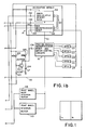
- a postage meter 12 includes an accounting module 14 having microprocessor and non-volatile memory such as a General Instrument Corporation ER3400 type electronically alterable read only memory, a printing module 16 having microprocessor and motor control circuits; and a control module 18 having a microprocessor and control circuits.
- accounting module 14 having microprocessor and non-volatile memory such as a General Instrument Corporation ER3400 type electronically alterable read only memory
- printing module 16 having microprocessor and motor control circuits
- a control module 18 having a microprocessor and control circuits.
- Postage meter 12 includes a series of opto-interrupters 20,22,24,26 and 28.
- the opto-interrupters are used to sense the mechanical position of parts of the meter.
- the opto-interrupters can be employed to sense the position of the shutter bar which is used to inhibit operation of the meter under certain circumstances, the position of the digit wheels, the home position of the print drum, the position of the bank selector for the print wheels, the position of the interposer, or any other movable mechanical component within the meter.
- These opto-interrupters are coupled to the printing module 16 which monitors and controls the position of the mechanical components of the meter.
- the printing module 16 is connected to the accounting module 14 via a serial data bus 30 and communicates by means of an ecoplex technique described in the above-noted US-A-4,301,507.
- Both ends of the bus are buffered by respective optics buffers, not shown, which are energized by the power supply +5 volt line to be hereafter described.
- the control module 18 is connected to the accounting module 14 via a serial data bus 32 and also communicates by means of the ecoplex technique.
- Optics buffers, not shown, are provided to buffer the bus. It should be recognized that the particular architecture of the postage meter system is not critical to the present invention, plural or single microprocessor arrangements may each be employed.
- a source of operating voltage such as (in the U.S.A.) 110 volts 60 Hertz supply, is applied across meter input terminals 34.
- the voltage is applied to a linear +10.8 volt power supply 36.
- the output from the +10.8 volt linear power supply 36 is supplied to a first +8 volt linear regulated power supply 38 and to a second +5 volt linear regulated power supply 40.
- the +8 volt power supply is used to power a display 42 which is operatively coupled via a bus 44 to the control module 18.
- the output from the power supply 40 is directly coupled to the control module 18 and is operated to energize the control module microprocessor.
- the AC operating voltage at terminals 34 is also applied to a silicon controlled rectifier-type, 24 volt power supply 46.
- the regulated output from the power supply 46 is applied to the print wheel bank stepper motor 48 and the print wheel stepper motor 50 associated with the printing module 16.
- the 24 volt DC power supply is coupled by an AC choke 52 to capacitor 54.
- the internal capacitance within the 24 volt power supply 46 provides sufficient energy storage to continue to properly energize a switching regulator 56 should an AC power failure occur at terminals 34.
- the accounting module microprocessor 58 transfers information from the postage meter volatile memory (which may be internal or external to the microprocessor) via a data bus 60 to a MNOS non-volatile memory 62.
- the switching regulator 56 in conjunction with a transformer 68 with related circuitry, provides regulated output voltages used to energize the accounting module.
- a level of +5 volts is developed and applied to the accounting module microprocessor 58, to MNOS non-volatile memory 62, to the optic buffers (not shown) for the serial data bus 30 connected between the accounting and the printing modules, to the printing module 16, and to the opto-interrupters 20-28.
- a level of -30 volts is also developed and is similarly applied via an NPN transistor 64 to the MNOS non-volatile memory 62. The -30 volts is required in conjunction with a supply of -12 volts which is also developed and applied to the MNOS non-volatile memory 62 and the supply of +5 volts to enable the non-volatile memory to have data written into the device.
- the switching regulator 56 functions to selectively apply the 24 volts developed across the capacitor 54 to the junction of a diode 66 and poled transformer primary winding 68.
- the frequency at which the regulator 56 operates or switches is determined by a capacitor 70 which controls the operating frequency of the supply.
- Primary winding 68 is further coupled to ground by a capacitor 72.
- Diode 66 and capacitor 72 form a complete circuit in parallel with the primary winding 68.
- the circuit path is through a point of fixed referenced potential, here shown as ground.
- a step-up secondary winding 78 oppositely poled to the primary winding is electromagnetically coupled via a permalloy core 80 to the primary winding 68.
- the secondary winding 78 is connected to ground at one end and has its opposite end coupled via a diode 82 which operates in conjunction with a capacitor 84 and a current limiting resistor 86 to develop -30 volts across a zener diode 88.
- a tap 90 on the secondary winding is connected to a diode 92 which operates in conjunction with a capacitor 94 and a current limiting resistor 96 to develop -12 volts across a zener diode 98.
- a circuit is provided to insure that the MNOS non-volatile memory 62 is not energized by the -30 volts necessary for a writing operating after a predetermined voltage condition in the power down sequence has been reached.
- This circuit operates in conjunction with a second circuit adapted to insure a proper reset is applied in a predetermined relationship to the application and the removal of the -30 volts from the non-volatile memory. The system insures that even if data is put onto the data bus 60 by the microprocessor 58, no data will be written into the MNOS non-volatile memory 62.
- the -30 volts supply to non-volatile memory 62 is passed through the collector-emitter current path of the NPN transistor 64.
- the collector electrode of the transistor is coupled via a resistor 64 to the +5 volts developed at capacitor 72.
- the voltage developed at the collector electrode of transistor 100 controls the voltage applied to the base electrode of a transistor 102 whose collector electrode is connected to the reset terminal 104 of the microprocessor 58 of the accounting module 14 and to the reset terminal 106 of the microprocessor for the printing module 16.
- Base bias for the transistor 64 is obtained from a PNP transistor 108.
- the emitter electrode of the transistor 108 is connected by a 10 volt zener diode 110 to the 24 volt power supply 46.
- a resistor 112 provides a ground return for the base electrode of transistor 108.
- Resistors 114 and 116 are connected to the base electrode of transistor 64.
- a capacitor 118 is provided to further filter transients.
- the base electrode of transistor 102 is coupled to the collector electrode of transistor 64 by a resistor 120 and to the +5 volts developed at capacitor 72 by a resistor 122.
- a capacitor 124 is connected across the collector-emitter electrode current path of transistor 102.
- the collector electrode is further connected by a resistor 126 to the +5 volts developed at capacitor 72.
- the reset system can be employed with either single microprocessor or plural microprocessor electronic postage meter systems.
- a low voltage detector 128 with about 2 volts of hysteresis senses the falling voltage and initiates an interrupt signal which is supplied to an interrupt or restart (RST) terminal 130 on the accounting module microprocessor 58.
- the interrupt signal initiates an interrupt routine e.g. as in the system disclosed in the aforementioned US-A-4,285,050 for Electronic Postage Meter Operating Voltage Variation Sensing System.
- the interrupt routine completes all pending accounting functions and transfers all register readings from the internal microprocessor RAM to the external non-volatile memory 62.
- the -30 volts is required in conjunction with a -12 volts (which is also developed and applied to the MNOS non-volatile memory 62 -12 volts terminal 134) to have data written into the memory.
- a positive voltage is applied and information cannot be written into the memory.
- the +5 volts is likewise applied via resistors 100 and 120 and via resistor 122 to the base electrode of transistor 102.
- the activation of the reset terminal places the microprocessor in a known condition.
- the +5 volts applied to the MNOS non-volatile memory terminal 132 insures that no information can be written into the non-volatile memory 62 during the remainder of the power down cycle. This is because, as previously noted, a -30 volts must be applied to terminal 132 to enable a WRITE operation in the MNOS non-volatile memory 62.
- the microprocessors' reset terminals will have a reset signal applied (a ground level potential) as power decays until the voltage at the base electrode of transistor 102 falls below the level necessary to forward bias the base-emitter junction, usually approximately 7/10ths of a volt for many devices.
- the voltage from the +24 volts power supply 46 begins to charge up its capacitors including capacitor 54 as it builds towards the 24 volt output.
- zener diode 110 will break down and begin to conduct. This establishes a current flow through the collector-emitter electrode current path of transistor 108 which in turn biases transistor 64 into conduction.
- the -30 volts is coupled via resistor 120 to the base electrode of transistor 102 biasing the transistor out of conduction.
- transistor 102 is biased into conduction as the voltage builds by the +5 volts applied to its base electrode via resistors 100 and 120 and via resistor 122.
- the time delay due to charging the capacitor 124 and controlling the bias of transistor 102 from the -30 volts supply insures that the -30 volts potential is applied and has stabilized on the MNOS non-volatile memory -30 volt terminal 132 prior to the microprocessor reset terminals being released to enable the microprocessor to commence operation.
- the reset terminals 104 and 106 of the microprocessors are rendered active putting the microprocessors in the reset condition simultaneously with the removal of the -30 volts supply from the NMOS non-volatile memory terminal 132.
- postage meter refers to the general class of device for the imprinting of a defined unit value for governmental or private carrier delivery of parcels, envelopes or other like application for unit value printing.
- postage meter is utilized, it is both known and employed in the trade as a general term for devices utilized in conjunction with services other than those exclusively employed by governmental postage and tax services.
- private, parcel and freight services purchase and employ such meters as a means to provide unit value printing and accounting for individual parcels.
Landscapes
- Engineering & Computer Science (AREA)
- Computer Hardware Design (AREA)
- General Engineering & Computer Science (AREA)
- Physics & Mathematics (AREA)
- General Physics & Mathematics (AREA)
- Devices For Checking Fares Or Tickets At Control Points (AREA)
- Power Sources (AREA)
- Management, Administration, Business Operations System, And Electronic Commerce (AREA)
Claims (9)
- Elektronische Frankiermaschine, mit:
einer Eingangseinrichtung (34) zur Verbindung mit einer Betriebsspannungsquelle;
einer Druckeinrichtung (16, 48, 50) zum Portodrucken;
einer Abrechnungseinrichtung (14), die mit der Druckeinrichtung gekoppelt ist, um von der Druckeinrichtung gedrucktes Porto abzurechnen, wobei die Abrechnungseinrichtung eine Computereinrichtung (58) aufweist, die eine Rücksetzklemme (104) zum Empfang einer ersten vorbestimmten Rücksetzklemmenspannung (+5 Volt) aufweist, um die Computereinrichtung (58) dazu freizugeben, daß sie in einen Zustand zur Ausgabe von Daten versetzt wird, und zum Empfang einer zweiten vorbestimmten Rücksetzklemmenspannung (0 Volt), um die Computereinrichtung dagegen zu sperren, daß sie in einen Zustand zur Ausgabe von Daten versetzt wird, wobei die Abrechnungseinrichtung (14) weiterhin eine nicht-flüchtige Speichereinrichtung (62) aufweist, die betriebsmäßig an die Computereinrichtung (58) gekoppelt ist, um Abrechnungsdaten zu speichern, wenn die Betriebsspannungsquelle nicht so arbeitet, daß sie die Abrechnungseinrichtung versorgt, wobei die nicht-flüchtige Speichereinrichtung (62) eine Klemme (132) aufweist, die dann, wenn sie mit einer ersten Spannung mit einem ersten vorbestimmten Wert (-30 Volt) versorgt wird, die nicht-flüchtige Speichereinrichtung freigibt, so daß in deren Speicherplätze durch die Computereinrichtung Daten eingeschrieben werden, und die dann, wenn sie mit einer zweiten Spannung eines zweiten vorbestimmten Wertes (+5 Volt) versorgt wird, der sich von dem ersten vorbestimmten Wert unterscheidet, die nicht-flüchtige Speichereinrichtung dagegen sperrt, daß in ihre Speicherplätze durch die Computereinrichtung (58) Daten eingeschrieben werden;
einer ersten Spannungserzeugungseinrichtung (78, 86, 88) zur Erzeugung der Speicherklemmenspannung mit dem ersten Wert (-30 Volt);
einer zweiten Spannungserzeugungseinrichtung (68, 72) zur Erzeugung der Speicherklemmenspannung mit dem zweiten Wert (+5 Volt);
einer ersten Spannungsanlegungseinrichtung (64, 100, 108, 110), die an die erste Spannungserzeugungseinrichtung (78, 86, 88) gekoppelt ist, an die zweite Spannungserzeugungseinrichtung (68, 72), und an die Klemme (132) des nicht-flüchtigen Speichers, um die Spannung mit dem ersten Wert (-30 Volt) an die Klemme (132) des nicht-flüchtigen Speichers anzulegen, wenn die Betriebsspannungsquelle oberhalb eines vorbestimmten Pegels ist, und um die Spannung mit dem zweiten Wert (+5 Volt) an die Klemme (132) des nicht-flüchtigen Speichers anzulegen, wenn die Betriebsspannungsquelle unterhalb eines vorbestimmten Pegels liegt; und
einer zweiten Spannungsanlegungseinrichtung (102, 124, 126), die an die erste Spannungsanlegungseinrichtung (64, 100, 108, 110) und an die Computerrücksetzklemme (104) gekoppelt ist, um die Rücksetzklemme (104) während des Einschaltens der Maschine mit der ersten vorbestimmten Rücksetzklemmenspannung (+5 Volt) erst dann zu versorgen, nachdem die Klemme (132) des nicht-flüchtigen Speichers mit der Spannung mit dem ersten Wert (-30 Volt) versorgt wurde. - Frankiermaschine nach Anspruch 1, bei welcher die zweite Spannungsanlegungseinrichtung (102, 124, 126) weiterhin so ausgebildet ist, daß sie selektiv die Rücksetzklemme (104) mit der zweiten vorbestimmten Rücksetzspannung versorgt.
- Frankiermaschine nach Anspruch 1 oder 2, bei welcher die zweite Spannungsanlegungseinrichtung (102, 124, 126) so ausgelegt ist, daß sie die Rücksetzklemme (104) mit der zweiten vorbestimmten Rücksetzspannung versorgt, wenn die erste Spannungsanlegungseinrichtung (64, 100, 108, 110) die Spannung mit dem zweiten Wert (+5 Volt) an die Klemme (132) des nicht-flüchtigen Speichers anlegt, so daß die Computereinrichtung (58) in bezug auf den Betrieb zur Ausgabe von Daten gesperrt ist, wenn die nicht-flüchtige Speichereinrichtung (62) dagegen gesperrt wurde, daß in ihre Speicherplätze durch die Computereinrichtung (58) Daten eingeschrieben werden.
- Frankiermaschine nach Anspruch 1, bei welcher die erste und zweite Spannungsanlegungseinrichtung jeweils eine erste bzw. zweite Schaltvorrichtung (64, 102) für drei Klemmen aufweisen, jeweils mit einer ersten, einer zweiten und einer Steuerklemme:
wobei der Erste-Zweite-Klemmenstrompfad der ersten Vorrichtung (64) in Reihe zwischen die Klemme (132) des nicht-flüchtigen Speichers und die erste Spannungserzeugungseinrichtung geschaltet ist;
eine Einrichtung (114, 116, 108, 110) vorgesehen ist, um den Spannungspegel der Quelle oder der Betriebsspannung zu ermitteln;
eine Einrichtung vorgesehen ist, um die Steuerklemme der ersten Schaltvorrichtung (64) an die Ermittlungseinrichtung zu koppeln, so daß die Ermittlungseinrichtung die Leitfähigkeit des Ersten-Zweiten-Klemmenstrompfades der ersten Schaltvorrichtung (64) steuert; und
der Erste-Zweite-Klemmenstrompfad der zweiten Schaltvorrichtung (102) mit drei Klemmen zwischen die zweite Spannungserzeugungseinrichtung (68, 72) und einen Punkt mit festem Referenzpotential gekoppelt ist, die erste Klemme der zweiten Schaltvorrichtung mit drei Klemmen an die Rücksetzklemme (104) der Computereinrichtung gekoppelt ist, und die Steuerklemme der zweiten Schaltvorrichtung (102) mit drei Klemmen an die erste Klemme der ersten Schaltvorrichtung (64) mit drei Klemmen gekoppelt ist. - Frankiermaschine nach Anspruch 4, bei welcher die erste und die zweite Schaltvorrichtung mit drei Klemmen Transistoren sind.
- Frankiermaschine nach Anspruch 1, bei welcher
eine Datenbuseinrichtung (60) vorgesehen ist, um Datenklemmen der Computereinrichtung (58) und der nicht-flüchtigen Speichereinrichtung (62) zu koppeln, um die Computereinrichtung freizugeben, daß sie Daten von der nicht-flüchtigen Speichereinrichtung lesen und Daten in die nicht-flüchtige Speichereinrichtung einschreiben kann;
die erste Spannungsanlegungseinrichtung einen ersten Transistor (64) aufweist, der eine Emitterelektrode, eine Kollektorelektrode und eine Basiselektrode aufweist, wobei dessen Kollektor-Emitter-Elektrodenpfad zwischen die Klemme (132) des nicht-flüchtigen Speichers und die erste Spannungserzeugungseinrichtung (78, 86, 88) gekoppelt ist;
eine Widerstandseinrichtung (100) vorgesehen ist, um die Kollektorelektrode des ersten Transistors (64) an die zweite Spannungserzeugungseinrichtung (68, 72) zu koppeln;
die zweite Spannungsanlegungseinrichtung (102, 124, 126) einen zweiten Transistor (102) aufweist, der eine Kollektor-, eine Emitter- und eine Basiselektrode aufweist, wobei dessen Kollektor-Emitter-Elektrodenpfad zwischen die zweite Spannungserzeugungseinrichtung (68, 72) und einen Punkt mit festem Referenzpotential gekoppelt ist;
eine Einrichtung vorgesehen ist, um die Kollektorelektrode des zweiten Transistors (102) an die Rücksetzklemme (104) der Computereinrichtung zu koppeln;
eine Kondensatoreinrichtung (124) zwischen die Kollektor- und Emitterelektrode des zweiten Transistors (102) gekoppelt ist; und
Spannungsteilereinrichtungen (120, 122) an die Basiselektrode des zweiten Transistors (102) und zwischen die Kollektorelektrode des ersten Transistors (64) und die zweite Einrichtung gekoppelt sind. - Frankiermaschine nach Anspruch 6, bei welcher die Druckeinrichtung einen Mikroprozessor (16) aufweist, um den Betriebsablauf der Druckeinrichtung zu steuern, wobei der Mikroprozessor (16) der Druckeinrichtung eine Rücksetzklemme (106) aufweist, sowie eine Einrichtung, welche die Rücksetzklemme (106) des Druckmodul-Mikroprozessors (16) an die Kollektorelektrode des zweiten Transistors (102) koppelt.
- Frankiermaschine nach Anspruch 6 oder 7, die weiterhin aufweist:
einen dritten Transistor (108), der eine Emitter-, eine Kollektor- und eine Basiselektrode aufweist;
eine Zenerdiode (110);
eine Stromversorgung (46), die an die erste und zweite Spannungserzeugungseinrichtung angekoppelt und zu deren Versorgung ausgebildet ist; und
wobei der Kollektor-Emitter-Elektrodenpfad des dritten Transistors (108) in Reihe mit der Zenerdiode (110) zwischen die Stromversorgung (46) und die Basiselektrode des ersten Transistors (64) geschaltet ist. - Frankiermaschine nach Anspruch 8, bei welcher die Computereinrichtung (58), die in der Abrechnungseinrichtung vorgesehen ist, eine Unterbrechungsklemme (130) aufweist, wobei ein Niederspannungssensor (128) zwischen die Stromversorgung (46) und die Unterbrechungsklemme geschaltet ist.
Applications Claiming Priority (2)
| Application Number | Priority Date | Filing Date | Title |
|---|---|---|---|
| US06/434,097 US4547853A (en) | 1982-10-13 | 1982-10-13 | Electronic postage meter reset circuit |
| US434097 | 1982-10-13 |
Publications (3)
| Publication Number | Publication Date |
|---|---|
| EP0106320A2 EP0106320A2 (de) | 1984-04-25 |
| EP0106320A3 EP0106320A3 (en) | 1987-03-04 |
| EP0106320B1 true EP0106320B1 (de) | 1992-09-16 |
Family
ID=23722819
Family Applications (1)
| Application Number | Title | Priority Date | Filing Date |
|---|---|---|---|
| EP83110216A Expired - Lifetime EP0106320B1 (de) | 1982-10-13 | 1983-10-13 | Elektronische Frankiermaschine mit Rücksetzschaltkreis |
Country Status (5)
| Country | Link |
|---|---|
| US (1) | US4547853A (de) |
| EP (1) | EP0106320B1 (de) |
| JP (1) | JPH0614380B2 (de) |
| CA (1) | CA1214558A (de) |
| DE (1) | DE3382623T2 (de) |
Families Citing this family (20)
| Publication number | Priority date | Publication date | Assignee | Title |
|---|---|---|---|---|
| US4731728A (en) * | 1985-01-10 | 1988-03-15 | Pitney Bowes Inc. | Postage meter with means for preventing unauthorized postage printing |
| US4701856A (en) * | 1985-03-12 | 1987-10-20 | Pitney Bowes Inc. | Reset delay circuit for an electronic postage meter |
| US4747057A (en) * | 1985-03-12 | 1988-05-24 | Pitney Bowes Inc. | Electronic postage meter having power up and power down protection circuitry |
| US4998203A (en) * | 1985-03-12 | 1991-03-05 | Digiulio Peter C | Postage meter with a non-volatile memory security circuit |
| US4742469A (en) * | 1985-10-31 | 1988-05-03 | F.M.E. Corporation | Electronic meter circuitry |
| US4807141A (en) * | 1985-12-16 | 1989-02-21 | Pitney Bowes Inc. | Postage meter with microprocessor controlled reset inhibiting means |
| US5021963A (en) * | 1988-12-30 | 1991-06-04 | Pitney Bowes Inc. | EPM having an improvement in accounting update security |
| US5012425A (en) * | 1988-12-30 | 1991-04-30 | Pitney Bowes Inc. | EPM having an improvement in non-volatile storage of accounting data |
| US5340965A (en) * | 1989-04-05 | 1994-08-23 | Ascom Hasler Mailing Systems, Inc. | Mechanical postage meter resetting device and method |
| US5634000A (en) * | 1991-07-31 | 1997-05-27 | Ascom Autelca Ag | Power-fail return loop |
| GB9126998D0 (en) * | 1991-12-19 | 1992-02-19 | Alcatel Business Machines Limi | Franking machine |
| FR2722595B1 (fr) * | 1994-07-18 | 1996-10-04 | Neopost Ind Sa | Systeme d'affranchissement postal electronique ayant un programme d'exploitation rechargeable in situ |
| JP3571383B2 (ja) * | 1994-10-19 | 2004-09-29 | 株式会社日立製作所 | Icカード、icカードリードライト装置及び電子財布システム |
| US5701250A (en) * | 1995-04-07 | 1997-12-23 | Pitney Bowes Inc. | Setting by phone for counter resettable postage meters |
| US5712542A (en) * | 1995-05-25 | 1998-01-27 | Ascom Hasler Mailing Systems Ag | Postage meter with improved handling of power failure |
| US5822738A (en) | 1995-11-22 | 1998-10-13 | F.M.E. Corporation | Method and apparatus for a modular postage accounting system |
| US5918234A (en) | 1995-11-22 | 1999-06-29 | F.M.E. Corporation | Method and apparatus for redundant postage accounting data files |
| DE10221579A1 (de) * | 2002-05-08 | 2003-12-04 | Siemens Ag | Elektronische Speichereinrichtung für Kenngrößen und Umrechnungsfaktoren für elektronische Schutzeinrichtungen von Leistungsschaltern |
| DE10221571A1 (de) * | 2002-05-08 | 2003-12-04 | Siemens Ag | Elektrischer Leistungsschalter mit einem elektronischen Speicher für Kenngrößen und/oder Umrechnungsfaktoren |
| US9128690B2 (en) * | 2012-09-24 | 2015-09-08 | Texas Instruments Incorporated | Bus pin reduction and power management |
Citations (1)
| Publication number | Priority date | Publication date | Assignee | Title |
|---|---|---|---|---|
| EP0075825A2 (de) * | 1981-09-29 | 1983-04-06 | Pitney Bowes Inc. | Elektronisches Postgebührenfeststellsystem |
Family Cites Families (12)
| Publication number | Priority date | Publication date | Assignee | Title |
|---|---|---|---|---|
| FR2261694A5 (de) * | 1973-09-05 | 1975-09-12 | Honeywell Bull Soc Ind | |
| US4131942A (en) * | 1977-01-10 | 1978-12-26 | Xerox Corporation | Non-volatile storage module for a controller |
| US4224506A (en) * | 1978-03-24 | 1980-09-23 | Pitney Bowes Inc. | Electronic counter with non-volatile memory |
| US4224539A (en) * | 1978-09-05 | 1980-09-23 | Motorola, Inc. | FET Voltage level detecting circuit |
| US4234920A (en) * | 1978-11-24 | 1980-11-18 | Engineered Systems, Inc. | Power failure detection and restart system |
| CA1160744A (en) * | 1979-05-09 | 1984-01-17 | Jesse T. Quatse | Electronic postage meter having improved security and fault tolerance features |
| US4285050A (en) * | 1979-10-30 | 1981-08-18 | Pitney Bowes Inc. | Electronic postage meter operating voltage variation sensing system |
| US4302821A (en) * | 1979-10-30 | 1981-11-24 | Pitney-Bowes, Inc. | Interposer control for electronic postage meter |
| US4301507A (en) * | 1979-10-30 | 1981-11-17 | Pitney Bowes Inc. | Electronic postage meter having plural computing systems |
| US4327410A (en) * | 1980-03-26 | 1982-04-27 | Ncr Corporation | Processor auto-recovery system |
| JPS5825452Y2 (ja) * | 1981-02-06 | 1983-06-01 | 八重洲無線株式会社 | バックアップ回路 |
| US4442501A (en) * | 1981-02-26 | 1984-04-10 | Pitney Bowes Inc. | Electronic postage meter with weak memory indication |
-
1982
- 1982-10-13 US US06/434,097 patent/US4547853A/en not_active Expired - Lifetime
-
1983
- 1983-10-07 CA CA000438601A patent/CA1214558A/en not_active Expired
- 1983-10-13 JP JP58191644A patent/JPH0614380B2/ja not_active Expired - Lifetime
- 1983-10-13 DE DE8383110216T patent/DE3382623T2/de not_active Expired - Lifetime
- 1983-10-13 EP EP83110216A patent/EP0106320B1/de not_active Expired - Lifetime
Patent Citations (1)
| Publication number | Priority date | Publication date | Assignee | Title |
|---|---|---|---|---|
| EP0075825A2 (de) * | 1981-09-29 | 1983-04-06 | Pitney Bowes Inc. | Elektronisches Postgebührenfeststellsystem |
Also Published As
| Publication number | Publication date |
|---|---|
| JPH0614380B2 (ja) | 1994-02-23 |
| EP0106320A3 (en) | 1987-03-04 |
| CA1214558A (en) | 1986-11-25 |
| DE3382623T2 (de) | 1993-03-18 |
| DE3382623D1 (de) | 1992-10-22 |
| EP0106320A2 (de) | 1984-04-25 |
| JPS5991593A (ja) | 1984-05-26 |
| US4547853A (en) | 1985-10-15 |
Similar Documents
| Publication | Publication Date | Title |
|---|---|---|
| EP0106320B1 (de) | Elektronische Frankiermaschine mit Rücksetzschaltkreis | |
| US4445198A (en) | Memory protection circuit for an electronic postage meter | |
| US4534018A (en) | Non-volatile memory protection circuit with microprocessor interaction | |
| US4285050A (en) | Electronic postage meter operating voltage variation sensing system | |
| US4998203A (en) | Postage meter with a non-volatile memory security circuit | |
| EP0173249B2 (de) | Nichtflüchtiges Speichersystem mit Echtzeit- und Netzausfall-Datenspeicherfähigkeit für eine Frankiermaschine | |
| US4845632A (en) | Electonic postage meter system having arrangement for rapid storage of critical postage accounting data in plural nonvolatile memories | |
| EP0197345B1 (de) | Elektronische Frankiermaschine mit Einschalt- und Ausschalt-Schutzschaltkreis | |
| US4706215A (en) | Data protection system for electronic postage meters having multiple non-volatile multiple memories | |
| US4701856A (en) | Reset delay circuit for an electronic postage meter | |
| US4807141A (en) | Postage meter with microprocessor controlled reset inhibiting means | |
| US4472781A (en) | Power supply system | |
| EP0222197B1 (de) | Systeme zur nichtflüchtigen Speicherung von Daten und Frankiermaschinensysteme | |
| US4578758A (en) | Electronic postage meter having a regulated power supply system responsive to a voltage developed in a transformer primary winding circuit | |
| CA1211790A (en) | Power supply system | |
| CA1247254A (en) | Postage meter with a non-volatile memory security circuit | |
| JPS60167017A (ja) | マイクロコンピユ−タのリセツト装置 | |
| JPH0461783B2 (de) |
Legal Events
| Date | Code | Title | Description |
|---|---|---|---|
| PUAI | Public reference made under article 153(3) epc to a published international application that has entered the european phase |
Free format text: ORIGINAL CODE: 0009012 |
|
| AK | Designated contracting states |
Designated state(s): CH DE FR GB LI |
|
| RAP1 | Party data changed (applicant data changed or rights of an application transferred) |
Owner name: PITNEY BOWES INC. |
|
| PUAL | Search report despatched |
Free format text: ORIGINAL CODE: 0009013 |
|
| AK | Designated contracting states |
Kind code of ref document: A3 Designated state(s): CH DE FR GB LI |
|
| 17P | Request for examination filed |
Effective date: 19870428 |
|
| 17Q | First examination report despatched |
Effective date: 19871217 |
|
| GRAA | (expected) grant |
Free format text: ORIGINAL CODE: 0009210 |
|
| AK | Designated contracting states |
Kind code of ref document: B1 Designated state(s): CH DE FR GB LI |
|
| REF | Corresponds to: |
Ref document number: 3382623 Country of ref document: DE Date of ref document: 19921022 |
|
| ET | Fr: translation filed | ||
| PLBI | Opposition filed |
Free format text: ORIGINAL CODE: 0009260 |
|
| 26 | Opposition filed |
Opponent name: NEOPOST INDUSTRIE Effective date: 19930616 |
|
| PLBN | Opposition rejected |
Free format text: ORIGINAL CODE: 0009273 |
|
| STAA | Information on the status of an ep patent application or granted ep patent |
Free format text: STATUS: OPPOSITION REJECTED |
|
| 27O | Opposition rejected |
Effective date: 19950403 |
|
| REG | Reference to a national code |
Ref country code: GB Ref legal event code: IF02 |
|
| PGFP | Annual fee paid to national office [announced via postgrant information from national office to epo] |
Ref country code: FR Payment date: 20020918 Year of fee payment: 20 |
|
| PGFP | Annual fee paid to national office [announced via postgrant information from national office to epo] |
Ref country code: GB Payment date: 20021009 Year of fee payment: 20 |
|
| PGFP | Annual fee paid to national office [announced via postgrant information from national office to epo] |
Ref country code: CH Payment date: 20021023 Year of fee payment: 20 |
|
| PGFP | Annual fee paid to national office [announced via postgrant information from national office to epo] |
Ref country code: DE Payment date: 20021031 Year of fee payment: 20 |
|
| PG25 | Lapsed in a contracting state [announced via postgrant information from national office to epo] |
Ref country code: LI Free format text: LAPSE BECAUSE OF EXPIRATION OF PROTECTION Effective date: 20031012 Ref country code: GB Free format text: LAPSE BECAUSE OF EXPIRATION OF PROTECTION Effective date: 20031012 Ref country code: CH Free format text: LAPSE BECAUSE OF EXPIRATION OF PROTECTION Effective date: 20031012 |
|
| REG | Reference to a national code |
Ref country code: GB Ref legal event code: PE20 |
|
| REG | Reference to a national code |
Ref country code: CH Ref legal event code: PL |