EP0106365A2 - Kraftstoffeinspritz-Steuergerät für eine Innenbrennkraftmaschine - Google Patents
Kraftstoffeinspritz-Steuergerät für eine Innenbrennkraftmaschine Download PDFInfo
- Publication number
- EP0106365A2 EP0106365A2 EP83110423A EP83110423A EP0106365A2 EP 0106365 A2 EP0106365 A2 EP 0106365A2 EP 83110423 A EP83110423 A EP 83110423A EP 83110423 A EP83110423 A EP 83110423A EP 0106365 A2 EP0106365 A2 EP 0106365A2
- Authority
- EP
- European Patent Office
- Prior art keywords
- task
- fuel
- engine
- state
- fuel injection
- Prior art date
- Legal status (The legal status is an assumption and is not a legal conclusion. Google has not performed a legal analysis and makes no representation as to the accuracy of the status listed.)
- Withdrawn
Links
Images


Classifications
-
- F—MECHANICAL ENGINEERING; LIGHTING; HEATING; WEAPONS; BLASTING
- F02—COMBUSTION ENGINES; HOT-GAS OR COMBUSTION-PRODUCT ENGINE PLANTS
- F02D—CONTROLLING COMBUSTION ENGINES
- F02D35/00—Controlling engines, dependent on conditions exterior or interior to engines, not otherwise provided for
- F02D35/02—Controlling engines, dependent on conditions exterior or interior to engines, not otherwise provided for on interior conditions
-
- F—MECHANICAL ENGINEERING; LIGHTING; HEATING; WEAPONS; BLASTING
- F02—COMBUSTION ENGINES; HOT-GAS OR COMBUSTION-PRODUCT ENGINE PLANTS
- F02D—CONTROLLING COMBUSTION ENGINES
- F02D41/00—Electrical control of supply of combustible mixture or its constituents
- F02D41/24—Electrical control of supply of combustible mixture or its constituents characterised by the use of digital means
- F02D41/26—Electrical control of supply of combustible mixture or its constituents characterised by the use of digital means using computer, e.g. microprocessor
- F02D41/263—Electrical control of supply of combustible mixture or its constituents characterised by the use of digital means using computer, e.g. microprocessor the program execution being modifiable by physical parameters
-
- F—MECHANICAL ENGINEERING; LIGHTING; HEATING; WEAPONS; BLASTING
- F02—COMBUSTION ENGINES; HOT-GAS OR COMBUSTION-PRODUCT ENGINE PLANTS
- F02D—CONTROLLING COMBUSTION ENGINES
- F02D41/00—Electrical control of supply of combustible mixture or its constituents
- F02D41/02—Circuit arrangements for generating control signals
- F02D41/04—Introducing corrections for particular operating conditions
- F02D41/10—Introducing corrections for particular operating conditions for acceleration
- F02D41/105—Introducing corrections for particular operating conditions for acceleration using asynchronous injection
Definitions
- the present invention relates to a fuel control apparatus employing a microcomputer, and, more particularly, to a fuel injection apparatus in which additional fuel for acceleration compensation is injected in accordance with the state of acceleration detected on the basis of the opening of a throttle valve.
- a general purpose software that is a software in which correction, modification or addition can be effected onto the various control functions depending on the kind/use of car, is required in view of improvement in cost and/or in controllability.
- the amount of suction air in an engine has been indirectly detected on the basis of the pressure in a suction manifold, or the total amount of suchtion air per suction stroke has been obtained by directly detecting the air flow rate.
- the accuracy is poor, the variations and/or deterioration in performence of engine may affect the detection, and the responsibility is not so good.
- the latter method also has a disadvantage that a flow rate sensor having high accuracy (error: within + 1% of read value) and a wide dynamic range (1:50) is required, resulting in increase in cost.
- hot-wire sensor a so-called hot-wire type flow rate sensor (hereinafter referred to as a hot-wire sensor) as the flow rate sensor, becuase the hot-wire sensor has a characteristic allowing a wide dynamic range and reduction in cost can be expected.
- the suction air flow rate in engine is not constant but has pulsations, so that the output signal from a flow.rate sensor has a non-linear charactristic with respect to the suction air flow, it becomes necessary to obtain the air flow rate in suction stroke in the form of integration of instantaneous air flow rates, and complex operations are required for the integration. That is,-the hot-wire output voltages v shown in Fig. 1 can be obtained according to the following equation (1) : where q A represents the mass flow rate and C l , C 2 represent constants determined by the shape of intake manifold etc. This equation (1) can be changed into the following equation (2) :
- the average or mean air flow rate in one suction stroke Q A can be expressed as follows: where A6 represents a crank angle between two adjacent sampling points of q A .
- the amount of fuel injection Q F for one suction stroke can be expressed by the following equation (7) : where N represents the number of engine revolution and k a constant. This means that the amount of fuel injection Q F for one stroke can be determined on the basis of the obtained value of Q A and the number of engine revolution N.
- the basic fuel injection amount Q F can be obtained in such a manner as described above, acceleration can'not be smoothly effected by using only the thus obtained basic fuel injection amount Q F when acceleration becomes necessary, because of delay in computation of the value Q A , etc. It has been effected, therefore, to compensate the basic fuel injection amount in accordance with the detection of the state of acceleration on the basis of the change in the take-in amount of Q A .
- the suction air flow rate Q A has pulsations as described above and an error may occur in detection of the state of acceleration. This applies to the case of decelerating operation. Therefore, the state of acceleration or deceleration is detected on the basis of the detection of the opening of the throttle valve.
- the throttle opening TH is sampled at a predetermined regular interval of time, for example every 10 msec, (by interval interruption) so that the sampling value TH at present is compared every 10 msec with the sampling value TH(OLD) sampled before 30 msec to obtain the difference ATH therebetween and judgement is made such that the engine is in the state of acceleration when ⁇ TH > 0.
- additional fuel for the compensation for acceleration is additionally injected.
- Such a system for detecting the acceleration and injecting the additional fuel is shown in Japanese Patent Publication No. 49-45653 and U.S.P. No. 3,898,962.
- the injection is effected until the entire amount of fuel of the additional fuel injection has been injected.
- a designates a pulse for the basic fuel injection (basic injection pulse) having a pulse width determined in accordance with the equation (7)
- b which is hatched designates a pulse to be added to the basic injection pulse for adding the additional fuel injection to the basic fuel injection
- c designates an interruption pulse generated at a reqular interval of time, for example 10 msec after the basic injection pulse, for effecting the additional fuel injection.
- An object of the present invention relates to a fuel injection apparatus in which proper fuel control can be performed even in the case where the state of deceleration occurs when additional fuel injection is being effected in response to the detection of the state of acceleration.
- the present invention is intended to attain proper fuel control by stopping additional fuel injection upon the detection of-the state of deceleration when the additional fuel injection is being effected in response to the detection of the state of acceleration.
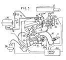
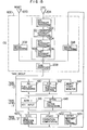
- a control apparatus for the whole of an engine system is illustrated.
- suction air is supplied to a cylinder 8 through an air cleaner 2, a throttle chamber 4, and a suction pipe 6.
- a gas burnt in the cylinder 8 is dishcarged from the cylinder 8 to the atomospher through an exhaust pipe 10.
- An injector 12 for injecting fuel is provided in the throttle chamber 4. The fuel injected from the injector 12 is atomized in an air path of the throttle chamber 4 and mixed with the suction air to form a fuel-air mixture which is in turn supplied to a combustion chamber of the cylinder 8 through the suction pipe 6 when a suction valve 20 is opened.
- Throttle valves 14 and 16 are provided in the vicinity of the output of the injector 12.
- the throttle valve 14 is arragned so as to mechanically interlocked with an accelerator pedal (not shown) so as to be driven by the driver.
- the throttle valve 16 is arranged to be driven by a diaphragm 18 such that it becomes its fully close state in a range where the air flow rate i ' s small, and as the air flow rate increases the negative pressure applied to the diaphragm 18 also increases so that the throttle valve 16 begins to open, thereby suppressing the increase of suction resistance.
- An air path 22 is provided at the upper stream of the throttle valves 14 and 16 of the throttle chamber 4 and an electrical heater 24 constituting a thermal air flow rate meter is provided in the air path 22 so as to derive from the heater 24 and electric signal which changes in accordance with the air flow velocity which is determined by the relation between the air flow velocity and the amount of heat transmission of the heater 24.
- the heater 24 Being provided in the air path 22, the heater 24 is protected from the high temperature gas generated in the period of back fire of the cylinder 8 as well as from the pollution by dust or the like in the suction air.
- the outlet of the air path 22 is opened in the vicinity of the narrowest portion of the venturi and the inlet of the same is opened at the upper stream of the venturi.
- Throttle opening sensors (not shown in Fig.3 but generally represented by a throttle opening sensor 116 in Fig.6) are respectively provided in the throttle valves 14 and 16 for detecting the opening thereof and the detection signals from these throttle opening sensors, that is the sensor 116, are taken into a multiplexer 120 of a first analog-to-digital converter as shown in Fig.6.
- the fuel to be supplied to the injector 12 is first supplied to a fuel pressure regulator 38 from a fuel tank 30 through a fuel pump 32, a fuel damper 34, and a filter 36. Pressurized fuel is supplied from the fuel pressure regulator 38 to the injector 12 through a pipe 40 on one hand and fuel is returned on the other hand from the fuel pressure regulator 38 to the fuel tank 30 through a return pipe 42 so as to maintain constant the difference between the pressure in the suction pipe 6 into which fuel is injected from the injector 12 and the pressure of the fuel supplied to the injector 12.
- the fule-air mixture sucked through the suction valve 20 is compressed by a piston 50, burnt by a spark produced by an ignition plug 52, and the combustion is converted into kinetic energy.
- the cylinder 8 is cooled by cooling water 54, the temperature of the cooling water is measured by a water temperature sensor 56, and the measured value is utilized as an engine temperature.
- a high voltage is applied from an ignition coil 58 to the ignition plug 52 in agreement with the ignition timing.
- a crank angle sensor (not shown) for producing a reference angle signal at a regular interval of predetermined crank angles (for example 180 degrees) and a -position signal at a regular interval of a predetermined unit crank angle (for example 0.5 degrees) in accordance with the rotation of engine, is provided on a not-shown crank shaft.
- the output of the crank angle sensor, the output 56A of the water temperature sensor 56, and the electrical signal from the heater 24 are inputted into a control circuit 64 constituted by a microcomputer or the like so that the injector 12 and the ignition coil 58 are driven by the output of this control circuit 64.
- a bypass 26 bypassing the throttle valve 16 to communicate with the suction pipe 6 is provided and a bypass valve 62 is provided in the bypass 26.
- a control signal is inputted to a drive section of the bypass valve 62 from the control circuit 64 to control the opening of the bypass valve 62.
- the opening of the bypass valve 62 is controlled by a pulse current such that the cross- sectional area of the bypass 26 is changed by the amount of lift of valve which is in turn controlled by a drive system driven by the output of the control circuit 64. That is, the control circuit 64 produces an open/close period signal for controlling the drive system so that the drive system responds to this open/close period signal to apply a control signal for controlling the amount of lift of the bypass valve 62 to the drive section of the bypass valve 62.
- a pulse current is supplied to a power transistor 72 through an amplifier 68 to energize this transistor 72 so that a primary coil pulse current flows into an ignition coil 58 from a battery 66.
- the transistor 74 is turned off so as to generate a high voltage at the secondary coil of the ignition coil 58.
- This high voltage is distributed through a distributor 70 to ignition plugs 52 provided at the respective cylinders in the engine, in synchronism with the rotation of the engine.
- a predetermined negative pressure of a negative pressure source 80 is applied to an EGR control valve 86 through a pressure control valve 84.
- the pressure control valve 84 controls the ratio with which the predetermined negative pressure of the negative pressure source is released to the atomosphere 88, in response to the ON duty factor of the repetitive pulse applied to a transistor 90, so as to control the state of application of the negative pressure pulse to the EGR control valve 86. Accordingly, the negative pressure applied to the EGR control valve 86 is determined by the ON duty factor of the transistor 90 per se.
- the amount of EGR from the exhaust pipe 10 to the suction pipe 6 is controlled by the controlled negative pressure of the pressure control valve 84.
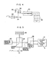
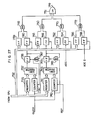
- Fig.6 is a diagram showing the whole configuration of the control system which is constituted by a central processing unit (hereinafter abbreviated as CPU) 102, a read only memory (hereinafter abbreviated as a ROM) 104, a random access memory (hereinafter abbreviated as RAM) 106, and an input/output (hereinafter abbreviated as I/O) circuit 108.
- the CPU 102 operates input date from the I/O circuit 108 in accordance with various programs stored in-the ROM 104 and returns the result of operation to the I/O circuit 108. Temporary data storage necessary for such an operation is performed by using the RAM 106. Exchange of various data among the CPU 102, the ROM 104, the RAM 106, and the I/O circuit 108 is performed through a bus line 110 constituted by a data bus, a control bus, and an address bus.
- a bus line 110 constituted by a data bus, a control bus, and an address bus.
- the I/O circuit 108 includes input means such as the above-mentioned first analog-to-digital converter (hereinafter abbreviated as ADC1), a second analog-to-digital converter (hereinafter abbreviated as ADC2), an angular signal processing circuit 126, and a discrete I/O circuit (hereinafter abbreviated as DIO) for inputting/outputting one bit information.
- ADC1 first analog-to-digital converter
- ADC2 second analog-to-digital converter
- DIO discrete I/O circuit
- the digital value of the output of the ADC 122 is stored in a register (hereinafter abbreviated as REG) 124.
- An output signal of an air flow rate sensor (hereinafter abbreviated as AFS) 24 is inputted to the AD C2 in which the signal is A/D converted in an ADC 128 and set in a REG 130.
- AFS air flow rate sensor
- An angle sensor (hereinafter abbreviated as ANGS) 146 produces a reference signal representing a reference crank angle (hereinafter abbreviated as REF), for example as a signal generated at an interval of 180 degrees of crank angle, and a position signal representing a small crank angle (hereinafter abbreviated as POS), for example 1 (one) degree.
- REF reference crank angle
- POS position signal representing a small crank angle
- the REF and POS are applied to the angular signal processing circuit 126 to be waveform-shaped therein.
- IDLE-SW idle switch 148
- TOP-SW top gear switch
- START-SW starter switch
- An injector circuit (hereinafter abbreviated as INJC) 134 is provided for converting the digital value of the result of operation into a pulse output. Accordingly, a pulse having a pulse width corresponding to the amount of fuel injection is generated in the INJC 134 and applied to the injector 12 through an AND gate 136.
- An ignition pulse generating circuit (hereinafter abbreviated as IGNC) 138 includes a register (hereinafter referred to as ADV) for setting ignition timing and another register (hereinafter referred to as DWL) for setting initiating timing of the primary current conduction of the ignition coil 58 and these data are set by the CPU 102.
- the ignition pulse generating circuit 138 produces a pulse on the basis of the thus set data and supplies this pulse through an AND gate 140 to the amplifier 68 described in detail with respect to Fig.4.
- the rate of opening of the bypass valve 62 is controlled by a pulse supplied thereto by a control circuit (hereinafter referred to as ISCC) 142 through an AND gate 144.
- the ISCC 142 has a register ISCD for setting a pulse width and another register ISCP for setting a repetitive pulse period.
- the output pulse of the EGRC 154 is applied to the transistor 90 through an AND gate 156.
- the one-bit I/O signals are controlled by the circuit DIO.
- the I/O signals include the respective output signals of the IDLE-SW 148, the TOP-SW 150 and the START-SW 152 as input signals, and include a pulse signal for controlling the fuel pump 32 as an output signal.
- the DIO includes a register DDR for determining whether a terminal be used as a data inputting one or a data outputting one, and another register DOUT for latching the output data.
- a register (hereinafter referred to as MOD) 160 is provided for holding commands instructing various internal states of the I/O circuit 108 and arranged such that, for example, all the AND gates 136, 140, 144, and 156 are turned on/off by setting a command into the NOD 160.
- the stoppage/start of the respective outputs of the INJC 134, IGNC 138, and ISCC 142 can be thus controlled by setting a command into the MOD 160.
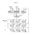
- Fig.7 is a diagram illustrating a basic configuration of a program system of the control circuit of Fig.6.
- an initial processing program 202 is for executing preprocessing for causing a microcomputer to operate.
- the initial processing program 202 for example, the contents of storage of the RAM 106 is cleared, the initial values of registers in the I/O interface circuit 108 are set, and processing for taking-in data, such as the cooling water temperature Tw, the battery voltage, for performing the preprocessing necessary for performing the engine control is executed.
- the interruption processing program 206 receives various interruptions, analyzes the factors of the interruptions, and produces a request for causing a desired one of tasks 210 to 226 to the task dispatcher 208.
- the interruption factors include an A/D conversion interruption (ADC) generated upon the completion of A/D conversion of the input data such as the power source voltage, the cooling water temperature as described later, an initial interruption (INTL) generated in synchronism with the engine revolution, an interval interruption (IN TV ) generated at a predetermined interval of time, for example every 10 msec, an engine stoppage interruption ( E NST) generated upon the detection of the engine stoppage, or the like.
- ADC A/D conversion interruption
- INTL initial interruption
- I TV interval interruption
- E NST engine stoppage interruption
- Task numbers representing priolity are allotted to the tasks 210 to 226, and the respective tasks belong to any one of the task levels "0", "1", and "2". That is, the task Nos. 0 to 2 belong to the task level "0", the task Nos. 3-to 5 belong to the task level "1", and the task Nos. 6 to 8 belong to the task level "2".
- the task dispatcher 208 Upon the reception of the activation requests by the above-mentioned various interruptions, the task dispatcher 208 responds to the activation requests to allot occupation time onto the CPU to the respective tasks in accordance with the priority rank attached to the respective tasks corresponding to the activation requests.
- the task priority control by the task dispatcher 208 is performed by the following method:
- Fig.8 shows task blocks of the same number as that of the task levels, that is three in this embodiment since there are three task levels "0" to "2", are provided in the RAM controlled by the dispatcher 208.
- Eight bits are allotted to each control block.
- Three of the eight bits, that is 0-th to 2nd bits (Q O - Q 2 ) are the activation bits for performing activation request task indication and the 7-th bit (R) is used for execution bit for indicating whether any one of the same task level is being executed or being interrupted.
- the activation bits Qo - Q 2 are arranged in the order of decreasing the priority rank.
- the activation bit corresponding to the task No.4 in Fig.7 is Qo in the task level "1".
- a flag "1" is set to any one of the activation bits, and at the same time the task dispatcher 208 searches for the issued activation request in the activation bits in the order from the activation bit corresponding to the task of higher level so that the flag corresponding to the issued activation request is reset and flag "1" is set to the execution bit to thereby execute the processing for activating the task corresponding thereto.
- Fig.9 shows an activation address table provided in the RAM 106 controlled by the task dispatcher 208.
- SAO to SA8 represent the activation addresses correspond to the task Nos.0 to 8 of the tasks 210 to 226 as shown in Fig.7.
- Sixteen bits are allotted to each activation address information which is used for the task dispatcher 208, as described later, to activate the task corresponding to the issued activation request.
- Figs.10 and 11 show flowcharts for the processing performed by the task dispatcher 208.
- judgement is made as to whether the tasks belonging to the task level t are being executed or interrupted in a step 302. That is, if flag "1" is detected in the execution bit, the flag "1" indicates the state that the macro processing program 228 does not yet issue the task completion information to the task dispatcher 208 and the task which had been executed is being interrupted because interruption of higher priority rank has been generated. Accordingly, if flag "1" is detected in the execution bit, the processing is jumped to'a step 314 in which the interrupted task is reactivated.
- the processing is shifted to the step 304 in which judgement is made as to whether there is any task waiting for activation in the level l. That is, the activation bits in the level l are searched for in the order of decreasing the priority rank of the tasks corresponding to the activation bits, that is in the order of Q 0 , Q 1 and Q 2 . If no flag "1" is detected in any one of the activation bits belonging to the level l, the processing comes to a step 306 in which the task level is altered. That is, the task level 1 is incremented by +1 so as to be l+1.
- the processing comes to a step 308 in which judgement is made as to whether all the task levels have been checked. In the case where all the task levels have been not yet checked, that is, when l ⁇ 2 in this embodiment, the processing comes back to the step 302 and the above-mentioned processing is repeated. In the case where the result of judgement proves that all the task levels have been checked in the step 308, the processing comes to a step 310 in which inhibit to interruption is released because interruption has been inhibited during the processing in the steps 302 to 308. Thereafter, in the next step 312, next issued interruption is waited for.
- step 400 If there is a task waiting for activation in the level l in the step 304, that is if flag "1" is detected in one of the activation bits belonging to the task level L, the processing comes to a step 400.
- search is made as to which one of the activation bits in which one of the task levels is provided with flag "1", in the order of decreasing the priority rank of the task levels, that is in the order of Q 0 , Q 1 , and Q 2 .
- the processing comes to a step 404 in which the activation bit provided with flag "1” is reset and flag "1" is set to the execution bit (hereinafter referred to R) of the same task level.
- step 406 the number of the activated task is detected, and in a step 408, the activation address information as to the activated task is derived in accordance with the activation address table provided in the RAM as shown in Fig.9.
- a step 410 judgement is made as to whether the activated task be executed or not.
- the necessity of the execution is judged on the basis of the value of the activation address information. That is, when the activation address information has a specific value, for example "0", the judgement is such that the execution is not necessary. It is necessary to provide this judgement step in order to cause a car to have a function of performing only a specific one of the task functions for performing engine control selected depending on the kind of the car.
- the processing comes to a step 414 in which the R-bit of the specific task level t is reset. then, the processing comes back to the step 302 in which judgement is made as to whether the task level l is being interrupted or not. This is because there may be a case where a plurality of activation bits are provided with flag "1".
- the processing comes to a step 412 in which jump is made to the specific task so as to execute the task.
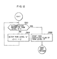
- Fig.12 shows a flowchart for processing the macro processing program 228.
- This program is constituted by steps 562 and 564.
- the task levels are searched in the order of increasing the task level, that is in the order from the level "0" so as to find completed task level or levels.
- the processing comes to a step 568 in which the execution (RUN) flag provided in the 7th bit in the task control block of the completed task is reset. thus, the execution of the task has been completed.
- the processing comes back to the task dispatcher 208 in which the next execution task is determined.
- the execution of the CPU is shifted to the control program OS
- the completion of execution of the task No.3 is reported by the macro program 228 to the task dispatcher 208
- the execution of the task No.4 corresponding to the activation request N 12 of lower priority rank is initiated at the time T 11
- the execution is shifted to the control program OS upon the completion of execution of the task No.4 at the time T 12
- the execution of the task No.6 which corresponds to the activation request N 21 and which has been so far interrupted is restarted at the time T 13 .
- the task priority control is performed in the manner as described above.
- the state of transition in the task priority control is illustrated in Fig.14 "Idle" represents the state in which activation is waited for and no task activation request has been issued. Then, if an activa- tin request is issued, flag "1" is set to the activation bit of the task control block so as to indicate the necessity of activation.
- the time required for shifting from the state “Idle” to the state “Queue” is determined by the level of the respective task. In the state "Queue", the order of execution is determined on the basis of the rank of priority.
- the specific task is brought into the state of execution after the flag of the activation bit of the task control block has been reset by the task dispatcher 208 in accordance with the control program OS and a flag "1" has been set to.the R-bit (7th bit).
- the execution of task is initiated. This is the state "Run”.
- the flag of the R-bit of the task control block is cleared and the completion report is terminated.
- the state "Run” ends and the state "Idle” is recovered to wait for the issuance of the next activation request. If an interruption request IRQ is generated in executing a task, that is in the state "Run", the execution of the task has to be interrupted. For this, the contents of the CPU is shunted and the execution is interrupted.
- Fig.l4 shows a typical flow. However, there may be a case where a flag "1" is set to the activation bit of the task control block in the state "Ready”. This is the case, for example, in the state of interruption of activation of a task, the next activation request timing of the task is reached. In this case the flag in the R-bit takes preference and the task which is being interrupted is terminated.
- each of the tasks N os.0 to 7 is in any one of the four states of Fig.4.
- Fig.15 shows a particular embodiment of the program system as shown in Fig.7.
- a control program OS includes an initial processing program 202, an interruption processing program 206, a task dispatcher 208, and a macro processing program 228.
- the interruption program 206 includes various kinds of interruption processing programs in which an initial interruption processing (hereinafter referred to as an INTL interruption processin) 602 generates initial interruptions in the number of half the number of the engine cylinders per revolution, for example twice per revolution in the case of four cylinders, due to an initial interruption signal generated in synchronism with the engine revolution.
- the date indicative of the fuel injection timing computed by an EGI task 612 in response to the above-mentioned INTL interruption is set in a register INJD in the INJC 134 included in the I/O interface circuit 108 (Fig.6).
- An A/D conversion interruption processing 604 includes two kinds of interruption, that is, an ADC1 (Fig.6) interruption and an ADC2 ( F ig.6) interruption.
- the ADC1 (Fig.6) has the accuracy of 8 bits, and is used for inputting data such as the battery voltage, the cooling water temperture, the suction air temperature, the regulated voltage, etc., applied thereto.
- the ADC1 starts the A/D conversion as soon as the input point to the MPX 120 (Fig.6) is assigned, and issues the ADC1 interruption upon the completion of the A/D conversion.
- the ADC1 interruption is used only before cranking.
- the ADC 128 in the ADC2 (Fig.6) is used for inputting the data indicative of the air flow rate and generates the ADC2 interruption immediately after the A/D conversion.
- the ADC2 interruption is also used only before cranking.
- an INTV interruption signal is generated at a time interval of a predetermined time of, for example, 10 msec set in an INTV register (not shown) and is used as a basic signal for monitoring the activating timing of tasks to be activated at a predetermined interval of time.
- This INTV interruption signal updates the soft timer thereby activating the mask now ready to be activated.
- interruption processing program 608 is for detecting state of ENST and starts counting in response to the detection of an INTL interruption signal so as to issue an ENST interruption when no INTL interruption signal can not be detected within a predetermined period of time of, for example, 1 sec.
- the processing steps are performed in the manner as described above.
- Tasks belonging to the task level "0" include a fuel cutting processing task (hereinafter referred to as an AC task), a fuel injection control task (hereinafter referred to as an EGI task), and a starting timing monitoring task (hereinafter referred to as an MONIT task).
- Tasks belonging to the task level "1” include an AD1 input task (hereinafter referred to as an ADIN1 task) and a time coefficient processing task (hereinafter referred to as an AFCIA task).
- Tasks belonging to the task level "2" include an idling rotation control task (hereinafter referred to as an ISC task), a compensation computation task (hereinafter referred to as an HOSEI task), and a pre-starting processing task (hereinafter referred to as an ISTRT task).
- ISC task idling rotation control task
- HOSEI task compensation computation task
- ISTRT task pre-starting processing task
- Table 2 shows the allocation of the task levels and the functions of the individual tasks.
- Fig.16 shows the manner of processing of the output signal from the hot-wire type flow rate sensor employed in the present invention.
- the instantaneous air flow rate q A can be computed from the hot-wire sensor output voltage v from the equation (5). Since the instantaneous air flow rate q A is an instantaneous value in the pulsating state as shown in Fig.l6, it is sampled at a predetermined time interval At.
- the mean air flow rate Q A can be computed from the respective sampled values of the instantaneous air flow rate Q A according to the following equation:
- the air flow rate sucked into the cylinder can be obtained as from the equation (8).
- the integrated air flow rate can be obtained by the above-mentioned signal processing.
- the fuel injection may be performed in such a manner that the amount of fuel injected per revolution of the engine is computed on the basis of the equation (7), to thereby perform fuel injection once per one suction stroke in each cylinder, for example, once every 180° rotation of the crank in the case of engine provided with 4 cylinders.
- the fuel injection may be performed when the integrated air flow rate actual value attains a given level.
- Fig.17 shows the timing of fuel injection according to the above-mentioned latter fuel injection system.
- the instantaneous air flow rate q A is integrated for a predetermined period of time, and, when the integrated air flow rate actual value attains or exceeds an integrated air flow rate reference level Q l , fuel is injected for a predetermined period of time t as seen in Fig.l7. That is, fuel is injected at the timing at which the integrated instantaneous air flow rate actual value has attained the integrated air flow rate referece level Q l .
- FIG. 17 there are shown three integrated air flow rate reference levels Q l1 , Q12 and Q l3 .
- the integrated air flow rate reference value 0 1 is suitably shifted so as to adjust the air-fuel ratio (A/F) as described.
- a rich fuel-air mixture is required during warming-up in the engine starting stage, and this can be achieved by reducing the integrated air flow rate reference level Q l .
- the integrated air flow rate reference level Qy can be suitably adjusted by the ON-OFF of the output from an 0 2 sensor (not shown).
- Fig.18 is a flowchart for processing the taking-in of the output signal of the hot-wire type flow rate sensor and the timing of the fuel injection.
- step 801 judgement is made in a step 801 as to whether the interruption is an INTL interruption or not.
- the ADV REG in IGNC 138 is set so as to complete the INTL interruption processing program.
- step 801 When the result of judgement in the step 801 proves that the interruption is a Q A timer interruption, activation is made for taking-in the output of the hot-wire type flow rate sensor in a step 806, ' and taking-in of the output of the hot-wire type flow rate sensor is performed in a step 807.
- the instantaneous air flow rate q A as shown in the equation (5) is computed in a step 808 and the integration processing is performed in a step 809. Judgement is made in a step 810 as to whether the integrated value of instantaneous air flow rate has reached the integrated air flow rate reference level.
- a period of time of fuel injection t corresponding to the integrated air flow rate reference level is set in a step 811 into the INJD REG of INJC 134 (Fig.6), and basic injection pulse is produced in a step 812 from the INJD REG of INJC 134 to the injector 12 through the AND gate 136 to initiate the injection with the basic fuel amount Tp.
- the width of the basic injection pulse is determined by the period of time t for injection, and the amount of basic fuel injection Tp is determined by the integrated air flow rate reference level.
- a step 813 the difference between the integrated air flow rate actual value and the integrated air flow rate reference level is computed to regard it as the present integrated air flow rate.
- the hot-wire type flow rate sensor is activated and the output of the same is taken-in in a step 817.
- the thus taken-in value of the air flow rate is used for detection of the engine start due to rotation torque of wheels.
- the processing is shifted to the INTV interruption processing 606 in Fig.lS.
- Fig.19 shows the relation between the temperature TW of engine cooling water sensed by the cooling water temperature sensor 56 and the air flow rate reference level. That is, Fig.19 shows how the reference level is varied relative to the output signal of the water temperature sensor 56.
- the temperature range of from -40°C to 40°C corresponds to the warming-up level in which the engine is started from its cold state.
- the temperature range from 40°C to 85°C corresponds to the normal starting level., and the temperature range higher than 85°C corresponds to the hot re-starting level.
- the sensor output signal indicative of the temperature of the engine cooling water is taken into to the ADC1 so that the air amount reference level corresponding to the sensed temperature can be set by comparison according to the relation shown in Fig.19.
- the INTST program 624 shown in Fig.15 is executed for this purpose.
- a step 901 the throttle opening is taken in by an INTV interruption at a period of time of 10 msec, and the thus taken-in value is A/D converted to store the A/D converted value into the RAM 106. Then, a difference ATH between the presently taken-in value of the throttle opening and a value of the throttle opening which has been taken in before 30 msec is obtained in a step 902, and judgement is made in a step 903 as to whether the state is of acceleration or not, that is, whether the value of ATH is positive or not.
- a fuel injection compensation factor K 1 for achieving acceleration is computed in a step 904 from the value of ATH representing the rate of change in throttle opening and the thus obtained compensation factor is stored in the RAM 106.
- the value of the basic fuel injection amount Tp obtained in the step 811 in Fig.l8 is multiplied by the fuel injection compensation factor K l to obtain an additional amount of fuel injection To for achieving acceleration in a step 905, and an additional fuel injection is performed in a step 906. That is, an interruption injection pulse as well as an additional injection pulse to be added to a basic injection pulse are produced.
- the interruption injection pulse c is produced at a regular period of time of 10 msec in the step 906 and the additional injection pulse b following the basic injection pulse a is produced, in addition to the basic injection pulse a produced-in the step 811 in Fig.18 as shown in Fig.21(B).
- the pulse width of each of the interruption and additional injection pulses is determined on the basis of the additional fuel injection amount T 0 .
- the interruption injection pulse c is produced at the regular period of time of 10 msec and the additional injection pulse b is produced in addition to the basic injection pulse a.
- the additional fuel injection may be performed by using either one of the interruption injection pulse and the addditional injection pulse.
- the acceleration injection compensation factor K l stored in the RAM is cleared in a step 907. That is, the additional injection is ceased.
- the interruption injection pulse c nor the additional injection pulse b are produced, but only the basic injection pulse a is produced.
- the interruption injection pulse c as well as the additional injection pulse b are cleared. Accordingly, as shown in Fig.21(C), the fuel-air mixture (F/A ratio) is prevented from becoming rich after the deceleration state has occurred.
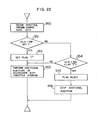
- the throttle opening change rate ATH is detected and stored in the RAM 106 in a step 950.
- Judgement is made in a step 951 as to whether the idle switch if in its OFF state or not.
- "1" is set to the flag provided in the RA M for the idle switch, in a step 952.
- the respective steps 904, 905, and 906 of Fig.20 are executed so that the additional injection amount To is computed on the basis of the throttle opening change rate ATH to perform additional injection in a step 953.
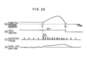
- Fig.23(A) therefore, when the accelerator pedal is depressed to open the throttle valve at the time t l , the idle switch is turned OFF and additional injection is performed. Thereafter, the additional injection is effected so long as the idle switch is in its OFF state (from the time t l to the time t 2 ).
- step 954 If the result of judgement in the step 954 proves that the flag of the idle switch is "1", on the contrary, it means that the state of the idle switch is switched from OFF to ON and therefore that the state of the engine is changed from acceleration to deceleration, so that the "1" of the flag of the idle switch is reset in a step 955.
- step 956 the processing is shifted to a step 956 in which the step 907 of Fig.20 is executed so that the acceleration injection compensation factor K l is cleared and the additional injection is ceased.
- the acceleration injection compensation factor Ki may be further compensated in accordance with the cooling water temperature T W .
- the additional injection amount To may be obtained from a map.
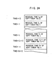
- Fig.24 shows a soft timer table which is provided in the RAM 106 and which is provided with timer blocks in the same number as that of different activation periods activated by various kinds of interruptions.
- the term "timer block” is defined as a storage area into which time information with respect to the activation period of the task stored in the ROM 104.
- TMB head address of the soft timer table in the RAM 106.
- the time information with respect to the above-mentioned activation period is stored from the ROM 104 in starting the engine. That is, when the INTV interruption is performed, for example, at a regular period of time of 10 msec, a value which is integral multiples of 10 msec and which represents the respective activation period is transferred and stored in the respective timer block.
- Fig.25 shows a flowchart for executing the INTV interruption processing 606.
- the judgement is concluded that the soft timer is in the state of stoppage and that the corresponding task to be activated by the specific soft timer is in the state of stoppage, so that processing is jumped to a step 640 in which the soft timer table is renewed. That is, the above-mentioned judgement is made on the basis of the fact that when the task is stopped, the residual timer is left it as it is without being initialized when it becomes 0 (zero).
- the processing is shifted to a step 632 in which the residual timer in the time block is renewed.
- the residual timer T 1 is decremented by 1 (one).
- the residual time T 1 of the soft timer table is initialized in the step 636. That is, the timer information with respect to the activation period of the specific task is transferred from the ROM 104 to the RAM 106.
- an activation request for the task corresponding to the soft timer table is issued in a step 638.
- the soft timer table is renewed in the step 640. That is, the contents of the soft timer table is incremented by 1 (one). Further judgement is made in a step 642 as to whether all the soft timers have been checked or not.
- the task ADIN1 is first activated so that the data, such as the cooling water temperature, the battery voltage, necessary for the starting of the engine are taken from the various sensors into the ADC 122 through the MPX 120, and every time all these data have been successively inputted, the task HOSEI, that is, the compensation task, is activated so that compensation is computed on the basis of the inputted data. Further, every time all the data from the various sensors have been successively inputted to the ADC 122 in accordance with the ADIN1, the task ISTRT is activated so that the fuel injection amount necessary in starting of the engine.
- the above-mentioned three tasks, that is, the task ADIN1, the task HOSEI and the task ISTRT are activated in accordance with the initial processing program 202.
- the three tasks that is, the task ADIN1, the task HOSEI and the task ISTRT are activated by the interruption signal of the task ISTRT. That is, these tasks have to be executed only in the period in which the START-SW 152 is in its ON state (in the period of cranking of the engine).
- pieces of time information with respect to the predetermined activation periods are transferred from the ROM 104 to the soft timer tables corresponding to the respective tasks provided in the RAM 106. Further, in this period, the residual time T 1 in the respective soft timer table is initialized and the setting of activation period is repeatedly performed.
- the task MONIT Being provided for computing the fuel injection amount in the starting of the engine, the task MONIT becomes unnecessary after the engine starting, and therefore after the task has been executed predetermined times, the activation of the soft timer is stopped and tasks necessary in the post-starting state of the engine other than the task MONIT are activated in response to a stoppage signal produced upon the termination of the task MONIT.
- "0" is stored in the soft timer table corresponding to the task in response to a signal indicating the termination of the task at the judgement point of time at the end of the task. That is, the stoppage of task is effected by clearing the contents of the soft timer corresponding to the task.
- Fig.27 shows an IRQ generating circuit.
- An INTV IRQ generating circuit is constituted by a register 735, a counter 736, a comparator 737, and a flip-flop 738, and a period for generating INTV IRQ, for example 10 msec, is set into the register 735.
- a clock pulse is set into the counter 736, and when the count of the counter 736 becomes coincident with the contents of the register 735, the flip-flop 738 is set. In this set state of the flip-flop 738, the counter 736 is cleared and the counting is restarted. Therefore, the INTV IRQ is generated at a predetermined regular interval of time (10 msec).
- An ENST IRQ generating circuit for detecting engine stoppage is constituted by a register 741, a counter 742, a comparator 743, and a flip-flop 744.
- the register 741, the counter 742 and the comparator 743 operate in the same manner as described above in the INTV IRQ generating circuit so that when the count of the counter 742 has reached the contents of the register 741, an ENST IRQ is generated.
- the counter 742 is cleared by an REF pulse generated by a crank angle sensor at a predetermined interval of crank angles during the rotation of engine, the count of the counter 742 can not reach the contents of the register 741 so that no ENST IRQ is generated.
- An INTV IRQ generated by the flip-flop 738, an ENST IRQ generated by the flip-flop 744, and IRQs generated by the ADC1 and ADC2 are set into flip-flops 740, 746, 764, and 768 respectively.
- a signal for generating/inhibiting IRQ is set into each of flip-flops 739, 745, 762, and 766. If "H” is set in any one of the flip-flops 739, 745, 762, and 766, corresponding one of AND gates 748, 750, 770, and 772 is enabled so that an IRQ is immediately generated through an OR gate 751.
- an IRQ can be generated, inhibited, or released from inhibition by setting "H” or "L” into the respective flip-flops 739, 745, 762 and 766.
- the cause of generation of IRQ is removed by taking the contents of the flip-flops 740, 746, 764 and 768 into the CPU.
Landscapes
- Engineering & Computer Science (AREA)
- Chemical & Material Sciences (AREA)
- Combustion & Propulsion (AREA)
- Mechanical Engineering (AREA)
- General Engineering & Computer Science (AREA)
- Computer Hardware Design (AREA)
- Microelectronics & Electronic Packaging (AREA)
- Electrical Control Of Air Or Fuel Supplied To Internal-Combustion Engine (AREA)
- Combined Controls Of Internal Combustion Engines (AREA)
Applications Claiming Priority (2)
| Application Number | Priority Date | Filing Date | Title |
|---|---|---|---|
| JP182903/82 | 1982-10-20 | ||
| JP57182903A JPS5974338A (ja) | 1982-10-20 | 1982-10-20 | 燃料噴射装置 |
Publications (2)
| Publication Number | Publication Date |
|---|---|
| EP0106365A2 true EP0106365A2 (de) | 1984-04-25 |
| EP0106365A3 EP0106365A3 (de) | 1984-12-19 |
Family
ID=16126387
Family Applications (1)
| Application Number | Title | Priority Date | Filing Date |
|---|---|---|---|
| EP83110423A Withdrawn EP0106365A3 (de) | 1982-10-20 | 1983-10-19 | Kraftstoffeinspritz-Steuergerät für eine Innenbrennkraftmaschine |
Country Status (3)
| Country | Link |
|---|---|
| EP (1) | EP0106365A3 (de) |
| JP (1) | JPS5974338A (de) |
| KR (1) | KR840006389A (de) |
Family Cites Families (4)
| Publication number | Priority date | Publication date | Assignee | Title |
|---|---|---|---|---|
| GB1323123A (en) * | 1969-10-22 | 1973-07-11 | Nissan Motor | Acceleration actuating device for fuel injection system |
| JPS6047460B2 (ja) * | 1977-10-19 | 1985-10-22 | トヨタ自動車株式会社 | 燃料噴射制御装置 |
| JPS5552531U (de) * | 1978-10-04 | 1980-04-08 | ||
| JPS575524A (en) * | 1980-06-11 | 1982-01-12 | Honda Motor Co Ltd | Fuel correcting device in acceleration of efi engine |
-
1982
- 1982-10-20 JP JP57182903A patent/JPS5974338A/ja active Pending
-
1983
- 1983-10-19 KR KR1019830004936A patent/KR840006389A/ko not_active Abandoned
- 1983-10-19 EP EP83110423A patent/EP0106365A3/de not_active Withdrawn
Also Published As
| Publication number | Publication date |
|---|---|
| JPS5974338A (ja) | 1984-04-26 |
| KR840006389A (ko) | 1984-11-29 |
| EP0106365A3 (de) | 1984-12-19 |
Similar Documents
| Publication | Publication Date | Title |
|---|---|---|
| US4482962A (en) | Engine control method | |
| US4658787A (en) | Method and apparatus for engine control | |
| US4630206A (en) | Method of fuel injection into engine | |
| US4310888A (en) | Technique for controlling the starting operation of an electronic engine control apparatus | |
| US4450815A (en) | Internal combustion engine control apparatus | |
| US4363097A (en) | Electronic type engine control method | |
| US4455980A (en) | Engine combustion control method | |
| EP0106366B1 (de) | Steuermethode für Brennkraftmaschine | |
| US4528964A (en) | Fuel injection control apparatus for internal combustion engine | |
| US4564907A (en) | Electronic control apparatus for internal combustion engine | |
| EP0110312A2 (de) | Motorsteuerungsmethode | |
| US4501249A (en) | Fuel injection control apparatus for internal combustion engine | |
| EP0030114A1 (de) | Verfahren zum Anlassen einer Brennkraftmaschine und Apparat dafür | |
| KR920003201B1 (ko) | 내연기관용 연료분사장치 | |
| EP0106365A2 (de) | Kraftstoffeinspritz-Steuergerät für eine Innenbrennkraftmaschine | |
| EP0077533B1 (de) | Vorrichtung und Verfahren zur Regelung bei Brennkraftmotoren | |
| JPH0138176B2 (de) | ||
| US4522178A (en) | Method of fuel control in engine | |
| EP0087802B1 (de) | Kraftstoffsteuerungsgerät für eine Innenbrennkraftmaschine | |
| EP0296323B2 (de) | Motorsteuerungsmethode | |
| JPS5974337A (ja) | 燃料噴射装置 | |
| JPS5841361A (ja) | 電子式エンジン制御装置 | |
| JPH01195943A (ja) | エンジンのアイドル回転数制御方法 | |
| JPH0118256B2 (de) | ||
| JPS63314352A (ja) | エンジン制御装置 |
Legal Events
| Date | Code | Title | Description |
|---|---|---|---|
| PUAI | Public reference made under article 153(3) epc to a published international application that has entered the european phase |
Free format text: ORIGINAL CODE: 0009012 |
|
| AK | Designated contracting states |
Designated state(s): DE FR GB IT SE |
|
| PUAL | Search report despatched |
Free format text: ORIGINAL CODE: 0009013 |
|
| AK | Designated contracting states |
Designated state(s): DE FR GB IT SE |
|
| 17P | Request for examination filed |
Effective date: 19841220 |
|
| STAA | Information on the status of an ep patent application or granted ep patent |
Free format text: STATUS: THE APPLICATION HAS BEEN WITHDRAWN |
|
| 18W | Application withdrawn |
Withdrawal date: 19860326 |
|
| RIN1 | Information on inventor provided before grant (corrected) |
Inventor name: KASHIWAYA, MINEO Inventor name: SAKAMOTO, MASAHIDE Inventor name: MORITA, KIYOMI |