EP0106465B1 - Méthode de développement d'images latentes électrostatiques - Google Patents
Méthode de développement d'images latentes électrostatiques Download PDFInfo
- Publication number
- EP0106465B1 EP0106465B1 EP19830304975 EP83304975A EP0106465B1 EP 0106465 B1 EP0106465 B1 EP 0106465B1 EP 19830304975 EP19830304975 EP 19830304975 EP 83304975 A EP83304975 A EP 83304975A EP 0106465 B1 EP0106465 B1 EP 0106465B1
- Authority
- EP
- European Patent Office
- Prior art keywords
- sleeve
- developer
- magnetic
- earing
- component
- Prior art date
- Legal status (The legal status is an assumption and is not a legal conclusion. Google has not performed a legal analysis and makes no representation as to the accuracy of the status listed.)
- Expired
Links
- 238000000034 method Methods 0.000 title claims description 22
- 239000002245 particle Substances 0.000 claims description 95
- 230000001737 promoting effect Effects 0.000 claims description 73
- 229910000859 α-Fe Inorganic materials 0.000 claims description 36
- 238000005520 cutting process Methods 0.000 claims description 26
- 230000007246 mechanism Effects 0.000 claims description 26
- 239000011230 binding agent Substances 0.000 claims description 15
- 239000006247 magnetic powder Substances 0.000 claims description 14
- 239000000203 mixture Substances 0.000 claims description 14
- 239000006185 dispersion Substances 0.000 claims description 12
- 239000000696 magnetic material Substances 0.000 claims description 11
- 239000000463 material Substances 0.000 claims description 2
- 229920005989 resin Polymers 0.000 description 20
- 239000011347 resin Substances 0.000 description 20
- -1 vinyl resins, acrylic Chemical compound 0.000 description 16
- 239000000843 powder Substances 0.000 description 14
- 230000000052 comparative effect Effects 0.000 description 11
- 235000014113 dietary fatty acids Nutrition 0.000 description 10
- 239000000194 fatty acid Substances 0.000 description 10
- 229930195729 fatty acid Natural products 0.000 description 10
- 150000004665 fatty acids Chemical class 0.000 description 10
- 230000015572 biosynthetic process Effects 0.000 description 9
- 230000000903 blocking effect Effects 0.000 description 9
- 238000011161 development Methods 0.000 description 9
- 238000002156 mixing Methods 0.000 description 9
- 238000009751 slip forming Methods 0.000 description 9
- 239000008240 homogeneous mixture Substances 0.000 description 8
- 239000001993 wax Substances 0.000 description 8
- 230000007613 environmental effect Effects 0.000 description 7
- JEIPFZHSYJVQDO-UHFFFAOYSA-N ferric oxide Chemical compound O=[Fe]O[Fe]=O JEIPFZHSYJVQDO-UHFFFAOYSA-N 0.000 description 7
- 230000009467 reduction Effects 0.000 description 7
- 238000003756 stirring Methods 0.000 description 7
- 238000010586 diagram Methods 0.000 description 6
- UQSXHKLRYXJYBZ-UHFFFAOYSA-N iron oxide Inorganic materials [Fe]=O UQSXHKLRYXJYBZ-UHFFFAOYSA-N 0.000 description 6
- 238000012360 testing method Methods 0.000 description 6
- VYPSYNLAJGMNEJ-UHFFFAOYSA-N Silicium dioxide Chemical compound O=[Si]=O VYPSYNLAJGMNEJ-UHFFFAOYSA-N 0.000 description 5
- UCNNJGDEJXIUCC-UHFFFAOYSA-L hydroxy(oxo)iron;iron Chemical compound [Fe].O[Fe]=O.O[Fe]=O UCNNJGDEJXIUCC-UHFFFAOYSA-L 0.000 description 5
- QIQXTHQIDYTFRH-UHFFFAOYSA-N octadecanoic acid Chemical compound CCCCCCCCCCCCCCCCCC(O)=O QIQXTHQIDYTFRH-UHFFFAOYSA-N 0.000 description 5
- 239000004698 Polyethylene Substances 0.000 description 4
- 235000021355 Stearic acid Nutrition 0.000 description 4
- 239000006229 carbon black Substances 0.000 description 4
- 239000011362 coarse particle Substances 0.000 description 4
- 238000009826 distribution Methods 0.000 description 4
- 239000003822 epoxy resin Substances 0.000 description 4
- IPCSVZSSVZVIGE-UHFFFAOYSA-N hexadecanoic acid Chemical compound CCCCCCCCCCCCCCCC(O)=O IPCSVZSSVZVIGE-UHFFFAOYSA-N 0.000 description 4
- SZVJSHCCFOBDDC-UHFFFAOYSA-N iron(II,III) oxide Inorganic materials O=[Fe]O[Fe]O[Fe]=O SZVJSHCCFOBDDC-UHFFFAOYSA-N 0.000 description 4
- 239000006249 magnetic particle Substances 0.000 description 4
- 230000005389 magnetism Effects 0.000 description 4
- OQCDKBAXFALNLD-UHFFFAOYSA-N octadecanoic acid Natural products CCCCCCCC(C)CCCCCCCCC(O)=O OQCDKBAXFALNLD-UHFFFAOYSA-N 0.000 description 4
- 229920000647 polyepoxide Polymers 0.000 description 4
- 229920000573 polyethylene Polymers 0.000 description 4
- 238000000926 separation method Methods 0.000 description 4
- 239000008117 stearic acid Substances 0.000 description 4
- 238000012546 transfer Methods 0.000 description 4
- 229910002012 Aerosil® Inorganic materials 0.000 description 3
- XEEYBQQBJWHFJM-UHFFFAOYSA-N Iron Chemical compound [Fe] XEEYBQQBJWHFJM-UHFFFAOYSA-N 0.000 description 3
- PPBRXRYQALVLMV-UHFFFAOYSA-N Styrene Chemical compound C=CC1=CC=CC=C1 PPBRXRYQALVLMV-UHFFFAOYSA-N 0.000 description 3
- YXFVVABEGXRONW-UHFFFAOYSA-N Toluene Chemical compound CC1=CC=CC=C1 YXFVVABEGXRONW-UHFFFAOYSA-N 0.000 description 3
- 230000009471 action Effects 0.000 description 3
- 125000004432 carbon atom Chemical group C* 0.000 description 3
- 239000003795 chemical substances by application Substances 0.000 description 3
- 229920001568 phenolic resin Polymers 0.000 description 3
- 239000000047 product Substances 0.000 description 3
- 238000007790 scraping Methods 0.000 description 3
- 239000007858 starting material Substances 0.000 description 3
- 229920002554 vinyl polymer Polymers 0.000 description 3
- 229920000178 Acrylic resin Polymers 0.000 description 2
- 239000004925 Acrylic resin Substances 0.000 description 2
- PXHVJJICTQNCMI-UHFFFAOYSA-N Nickel Chemical compound [Ni] PXHVJJICTQNCMI-UHFFFAOYSA-N 0.000 description 2
- 235000021314 Palmitic acid Nutrition 0.000 description 2
- 229920013620 Pliolite Polymers 0.000 description 2
- 239000004743 Polypropylene Substances 0.000 description 2
- RTAQQCXQSZGOHL-UHFFFAOYSA-N Titanium Chemical compound [Ti] RTAQQCXQSZGOHL-UHFFFAOYSA-N 0.000 description 2
- 229920000180 alkyd Polymers 0.000 description 2
- 150000001408 amides Chemical class 0.000 description 2
- 229920003180 amino resin Polymers 0.000 description 2
- 239000002585 base Substances 0.000 description 2
- 230000008901 benefit Effects 0.000 description 2
- UKMSUNONTOPOIO-UHFFFAOYSA-N docosanoic acid Chemical compound CCCCCCCCCCCCCCCCCCCCCC(O)=O UKMSUNONTOPOIO-UHFFFAOYSA-N 0.000 description 2
- POULHZVOKOAJMA-UHFFFAOYSA-N dodecanoic acid Chemical compound CCCCCCCCCCCC(O)=O POULHZVOKOAJMA-UHFFFAOYSA-N 0.000 description 2
- 230000000694 effects Effects 0.000 description 2
- 150000002148 esters Chemical class 0.000 description 2
- WSFSSNUMVMOOMR-UHFFFAOYSA-N formaldehyde Natural products O=C WSFSSNUMVMOOMR-UHFFFAOYSA-N 0.000 description 2
- 239000011521 glass Substances 0.000 description 2
- 238000005469 granulation Methods 0.000 description 2
- 230000003179 granulation Effects 0.000 description 2
- LNEPOXFFQSENCJ-UHFFFAOYSA-N haloperidol Chemical compound C1CC(O)(C=2C=CC(Cl)=CC=2)CCN1CCCC(=O)C1=CC=C(F)C=C1 LNEPOXFFQSENCJ-UHFFFAOYSA-N 0.000 description 2
- QQVIHTHCMHWDBS-UHFFFAOYSA-L isophthalate(2-) Chemical compound [O-]C(=O)C1=CC=CC(C([O-])=O)=C1 QQVIHTHCMHWDBS-UHFFFAOYSA-L 0.000 description 2
- HQKMJHAJHXVSDF-UHFFFAOYSA-L magnesium stearate Chemical compound [Mg+2].CCCCCCCCCCCCCCCCCC([O-])=O.CCCCCCCCCCCCCCCCCC([O-])=O HQKMJHAJHXVSDF-UHFFFAOYSA-L 0.000 description 2
- 230000004048 modification Effects 0.000 description 2
- 238000012986 modification Methods 0.000 description 2
- WQEPLUUGTLDZJY-UHFFFAOYSA-N n-Pentadecanoic acid Natural products CCCCCCCCCCCCCCC(O)=O WQEPLUUGTLDZJY-UHFFFAOYSA-N 0.000 description 2
- RKISUIUJZGSLEV-UHFFFAOYSA-N n-[2-(octadecanoylamino)ethyl]octadecanamide Chemical compound CCCCCCCCCCCCCCCCCC(=O)NCCNC(=O)CCCCCCCCCCCCCCCCC RKISUIUJZGSLEV-UHFFFAOYSA-N 0.000 description 2
- 239000000025 natural resin Substances 0.000 description 2
- 239000003921 oil Substances 0.000 description 2
- 239000005011 phenolic resin Substances 0.000 description 2
- XNGIFLGASWRNHJ-UHFFFAOYSA-N phthalic acid Chemical compound OC(=O)C1=CC=CC=C1C(O)=O XNGIFLGASWRNHJ-UHFFFAOYSA-N 0.000 description 2
- 229920001155 polypropylene Polymers 0.000 description 2
- 238000002360 preparation method Methods 0.000 description 2
- 238000010298 pulverizing process Methods 0.000 description 2
- 150000003839 salts Chemical class 0.000 description 2
- 125000000391 vinyl group Chemical group [H]C([*])=C([H])[H] 0.000 description 2
- AXWLFOKLQGDQFR-UHFFFAOYSA-N zinc iron(2+) manganese(2+) oxygen(2-) Chemical compound [O-2].[Fe+2].[Zn+2].[Mn+2].[O-2].[O-2] AXWLFOKLQGDQFR-UHFFFAOYSA-N 0.000 description 2
- DOQWNXVUTAWORG-YNKKZALPSA-N (z,12r)-12-hydroxy-n-[2-[[(z,12r)-12-hydroxyoctadec-9-enoyl]amino]ethyl]octadec-9-enamide Chemical compound CCCCCC[C@@H](O)C\C=C/CCCCCCCC(=O)NCCNC(=O)CCCCCCC\C=C/C[C@H](O)CCCCCC DOQWNXVUTAWORG-YNKKZALPSA-N 0.000 description 1
- KPAPHODVWOVUJL-UHFFFAOYSA-N 1-benzofuran;1h-indene Chemical compound C1=CC=C2CC=CC2=C1.C1=CC=C2OC=CC2=C1 KPAPHODVWOVUJL-UHFFFAOYSA-N 0.000 description 1
- ULQISTXYYBZJSJ-UHFFFAOYSA-N 12-hydroxyoctadecanoic acid Chemical compound CCCCCCC(O)CCCCCCCCCCC(O)=O ULQISTXYYBZJSJ-UHFFFAOYSA-N 0.000 description 1
- OEPOKWHJYJXUGD-UHFFFAOYSA-N 2-(3-phenylmethoxyphenyl)-1,3-thiazole-4-carbaldehyde Chemical compound O=CC1=CSC(C=2C=C(OCC=3C=CC=CC=3)C=CC=2)=N1 OEPOKWHJYJXUGD-UHFFFAOYSA-N 0.000 description 1
- KIHBGTRZFAVZRV-UHFFFAOYSA-N 2-Hydroxyoctadecanoic acid Natural products CCCCCCCCCCCCCCCCC(O)C(O)=O KIHBGTRZFAVZRV-UHFFFAOYSA-N 0.000 description 1
- ALVUHLMBSCMAIG-UHFFFAOYSA-N 2-hydroxy-n-(2-hydroxyethyl)octadecanamide Chemical compound CCCCCCCCCCCCCCCCC(O)C(=O)NCCO ALVUHLMBSCMAIG-UHFFFAOYSA-N 0.000 description 1
- KXGFMDJXCMQABM-UHFFFAOYSA-N 2-methoxy-6-methylphenol Chemical compound [CH]OC1=CC=CC([CH])=C1O KXGFMDJXCMQABM-UHFFFAOYSA-N 0.000 description 1
- 235000007173 Abies balsamea Nutrition 0.000 description 1
- RSWGJHLUYNHPMX-UHFFFAOYSA-N Abietic-Saeure Natural products C12CCC(C(C)C)=CC2=CCC2C1(C)CCCC2(C)C(O)=O RSWGJHLUYNHPMX-UHFFFAOYSA-N 0.000 description 1
- 229920002126 Acrylic acid copolymer Polymers 0.000 description 1
- 239000004857 Balsam Substances 0.000 description 1
- 235000021357 Behenic acid Nutrition 0.000 description 1
- 229910001369 Brass Inorganic materials 0.000 description 1
- 229910000906 Bronze Inorganic materials 0.000 description 1
- OKTJSMMVPCPJKN-UHFFFAOYSA-N Carbon Chemical compound [C] OKTJSMMVPCPJKN-UHFFFAOYSA-N 0.000 description 1
- 229920003043 Cellulose fiber Polymers 0.000 description 1
- 239000004859 Copal Substances 0.000 description 1
- 229920000742 Cotton Polymers 0.000 description 1
- 229910000737 Duralumin Inorganic materials 0.000 description 1
- 229910002608 Gd3Fe5O12 Inorganic materials 0.000 description 1
- 241000782205 Guibourtia conjugata Species 0.000 description 1
- 244000018716 Impatiens biflora Species 0.000 description 1
- 239000004166 Lanolin Substances 0.000 description 1
- 239000005639 Lauric acid Substances 0.000 description 1
- JHWNWJKBPDFINM-UHFFFAOYSA-N Laurolactam Chemical compound O=C1CCCCCCCCCCCN1 JHWNWJKBPDFINM-UHFFFAOYSA-N 0.000 description 1
- 229920000877 Melamine resin Polymers 0.000 description 1
- 229920000299 Nylon 12 Polymers 0.000 description 1
- 229920002292 Nylon 6 Polymers 0.000 description 1
- OAICVXFJPJFONN-UHFFFAOYSA-N Phosphorus Chemical compound [P] OAICVXFJPJFONN-UHFFFAOYSA-N 0.000 description 1
- 229920002845 Poly(methacrylic acid) Chemical class 0.000 description 1
- 239000004952 Polyamide Substances 0.000 description 1
- 239000004793 Polystyrene Substances 0.000 description 1
- OFOBLEOULBTSOW-UHFFFAOYSA-N Propanedioic acid Natural products OC(=O)CC(O)=O OFOBLEOULBTSOW-UHFFFAOYSA-N 0.000 description 1
- KHPCPRHQVVSZAH-HUOMCSJISA-N Rosin Natural products O(C/C=C/c1ccccc1)[C@H]1[C@H](O)[C@@H](O)[C@@H](O)[C@@H](CO)O1 KHPCPRHQVVSZAH-HUOMCSJISA-N 0.000 description 1
- 240000000111 Saccharum officinarum Species 0.000 description 1
- 235000007201 Saccharum officinarum Nutrition 0.000 description 1
- 241000872198 Serjania polyphylla Species 0.000 description 1
- 229920001800 Shellac Polymers 0.000 description 1
- 229920002125 Sokalan® Polymers 0.000 description 1
- 229910000831 Steel Inorganic materials 0.000 description 1
- 229920001807 Urea-formaldehyde Polymers 0.000 description 1
- XTXRWKRVRITETP-UHFFFAOYSA-N Vinyl acetate Chemical compound CC(=O)OC=C XTXRWKRVRITETP-UHFFFAOYSA-N 0.000 description 1
- BZHJMEDXRYGGRV-UHFFFAOYSA-N Vinyl chloride Chemical compound ClC=C BZHJMEDXRYGGRV-UHFFFAOYSA-N 0.000 description 1
- QYKIQEUNHZKYBP-UHFFFAOYSA-N Vinyl ether Chemical compound C=COC=C QYKIQEUNHZKYBP-UHFFFAOYSA-N 0.000 description 1
- 229910009493 Y3Fe5O12 Inorganic materials 0.000 description 1
- 229910001308 Zinc ferrite Inorganic materials 0.000 description 1
- NEKNPTMOEUCRLW-UHFFFAOYSA-N [O-2].[Fe+2].[Gd+3] Chemical compound [O-2].[Fe+2].[Gd+3] NEKNPTMOEUCRLW-UHFFFAOYSA-N 0.000 description 1
- GZHZIMFFZGAOGY-UHFFFAOYSA-N [O-2].[Fe+2].[La+3] Chemical compound [O-2].[Fe+2].[La+3] GZHZIMFFZGAOGY-UHFFFAOYSA-N 0.000 description 1
- 239000011354 acetal resin Substances 0.000 description 1
- 229910052783 alkali metal Inorganic materials 0.000 description 1
- 229910052784 alkaline earth metal Inorganic materials 0.000 description 1
- 150000001336 alkenes Chemical class 0.000 description 1
- AZDRQVAHHNSJOQ-UHFFFAOYSA-N alumane Chemical class [AlH3] AZDRQVAHHNSJOQ-UHFFFAOYSA-N 0.000 description 1
- 229910052782 aluminium Inorganic materials 0.000 description 1
- XAGFODPZIPBFFR-UHFFFAOYSA-N aluminium Chemical compound [Al] XAGFODPZIPBFFR-UHFFFAOYSA-N 0.000 description 1
- CEGOLXSVJUTHNZ-UHFFFAOYSA-K aluminium tristearate Chemical compound [Al+3].CCCCCCCCCCCCCCCCCC([O-])=O.CCCCCCCCCCCCCCCCCC([O-])=O.CCCCCCCCCCCCCCCCCC([O-])=O CEGOLXSVJUTHNZ-UHFFFAOYSA-K 0.000 description 1
- 229940063655 aluminum stearate Drugs 0.000 description 1
- 125000003277 amino group Chemical group 0.000 description 1
- HPYIMVBXZPJVBV-UHFFFAOYSA-N barium(2+);iron(3+);oxygen(2-) Chemical compound [O-2].[O-2].[O-2].[O-2].[O-2].[O-2].[O-2].[O-2].[O-2].[O-2].[O-2].[O-2].[O-2].[O-2].[O-2].[O-2].[O-2].[O-2].[O-2].[Fe+3].[Fe+3].[Fe+3].[Fe+3].[Fe+3].[Fe+3].[Fe+3].[Fe+3].[Fe+3].[Fe+3].[Fe+3].[Fe+3].[Ba+2] HPYIMVBXZPJVBV-UHFFFAOYSA-N 0.000 description 1
- 235000013871 bee wax Nutrition 0.000 description 1
- 235000015278 beef Nutrition 0.000 description 1
- 239000012166 beeswax Substances 0.000 description 1
- 229940092738 beeswax Drugs 0.000 description 1
- 229940116226 behenic acid Drugs 0.000 description 1
- 239000010951 brass Substances 0.000 description 1
- 239000010974 bronze Substances 0.000 description 1
- BAXLMRUQFAMMQC-UHFFFAOYSA-N cadmium(2+) iron(2+) oxygen(2-) Chemical compound [Cd+2].[O-2].[Fe+2].[O-2] BAXLMRUQFAMMQC-UHFFFAOYSA-N 0.000 description 1
- CJZGTCYPCWQAJB-UHFFFAOYSA-L calcium stearate Chemical compound [Ca+2].CCCCCCCCCCCCCCCCCC([O-])=O.CCCCCCCCCCCCCCCCCC([O-])=O CJZGTCYPCWQAJB-UHFFFAOYSA-L 0.000 description 1
- 239000008116 calcium stearate Substances 0.000 description 1
- 235000013539 calcium stearate Nutrition 0.000 description 1
- HRBZRZSCMANEHQ-UHFFFAOYSA-L calcium;hexadecanoate Chemical compound [Ca+2].CCCCCCCCCCCCCCCC([O-])=O.CCCCCCCCCCCCCCCC([O-])=O HRBZRZSCMANEHQ-UHFFFAOYSA-L 0.000 description 1
- 239000004204 candelilla wax Substances 0.000 description 1
- 235000013868 candelilla wax Nutrition 0.000 description 1
- 229940073532 candelilla wax Drugs 0.000 description 1
- 239000004203 carnauba wax Substances 0.000 description 1
- 235000013869 carnauba wax Nutrition 0.000 description 1
- 229910010293 ceramic material Inorganic materials 0.000 description 1
- 230000008859 change Effects 0.000 description 1
- 239000007795 chemical reaction product Substances 0.000 description 1
- 238000004140 cleaning Methods 0.000 description 1
- 229910017052 cobalt Inorganic materials 0.000 description 1
- 239000010941 cobalt Substances 0.000 description 1
- GUTLYIVDDKVIGB-UHFFFAOYSA-N cobalt atom Chemical compound [Co] GUTLYIVDDKVIGB-UHFFFAOYSA-N 0.000 description 1
- 238000007906 compression Methods 0.000 description 1
- 230000006835 compression Effects 0.000 description 1
- 238000001816 cooling Methods 0.000 description 1
- 229920001577 copolymer Polymers 0.000 description 1
- KUNSUQLRTQLHQQ-UHFFFAOYSA-N copper tin Chemical compound [Cu].[Sn] KUNSUQLRTQLHQQ-UHFFFAOYSA-N 0.000 description 1
- DXKGMXNZSJMWAF-UHFFFAOYSA-N copper;oxido(oxo)iron Chemical compound [Cu+2].[O-][Fe]=O.[O-][Fe]=O DXKGMXNZSJMWAF-UHFFFAOYSA-N 0.000 description 1
- 230000003247 decreasing effect Effects 0.000 description 1
- 230000007547 defect Effects 0.000 description 1
- 230000002950 deficient Effects 0.000 description 1
- 210000005069 ears Anatomy 0.000 description 1
- 239000005038 ethylene vinyl acetate Substances 0.000 description 1
- 238000002474 experimental method Methods 0.000 description 1
- 239000000835 fiber Substances 0.000 description 1
- 239000010419 fine particle Substances 0.000 description 1
- NZLGDGOPUXEZGO-UHFFFAOYSA-N formaldehyde;hexadecanamide Chemical compound O=C.CCCCCCCCCCCCCCCC(N)=O NZLGDGOPUXEZGO-UHFFFAOYSA-N 0.000 description 1
- DKMVUIBITPUCDG-UHFFFAOYSA-N formaldehyde;octadecanamide Chemical compound O=C.CCCCCCCCCCCCCCCCCC(N)=O DKMVUIBITPUCDG-UHFFFAOYSA-N 0.000 description 1
- IUJAMGNYPWYUPM-UHFFFAOYSA-N hentriacontane Chemical compound CCCCCCCCCCCCCCCCCCCCCCCCCCCCCCC IUJAMGNYPWYUPM-UHFFFAOYSA-N 0.000 description 1
- HSEMFIZWXHQJAE-UHFFFAOYSA-N hexadecanamide Chemical compound CCCCCCCCCCCCCCCC(N)=O HSEMFIZWXHQJAE-UHFFFAOYSA-N 0.000 description 1
- SSVSELJXJJCANX-UHFFFAOYSA-N hexadecanehydrazide Chemical compound CCCCCCCCCCCCCCCC(=O)NN SSVSELJXJJCANX-UHFFFAOYSA-N 0.000 description 1
- 229940042795 hydrazides for tuberculosis treatment Drugs 0.000 description 1
- 150000003840 hydrochlorides Chemical class 0.000 description 1
- NNGHIEIYUJKFQS-UHFFFAOYSA-L hydroxy(oxo)iron;zinc Chemical compound [Zn].O[Fe]=O.O[Fe]=O NNGHIEIYUJKFQS-UHFFFAOYSA-L 0.000 description 1
- 230000006872 improvement Effects 0.000 description 1
- 238000010348 incorporation Methods 0.000 description 1
- 239000004615 ingredient Substances 0.000 description 1
- 229910052742 iron Inorganic materials 0.000 description 1
- DMTIXTXDJGWVCO-UHFFFAOYSA-N iron(2+) nickel(2+) oxygen(2-) Chemical compound [O--].[O--].[Fe++].[Ni++] DMTIXTXDJGWVCO-UHFFFAOYSA-N 0.000 description 1
- ADCBYGNHJOLWLB-UHFFFAOYSA-N iron(2+) oxygen(2-) yttrium(3+) Chemical compound [Y+3].[O-2].[Fe+2] ADCBYGNHJOLWLB-UHFFFAOYSA-N 0.000 description 1
- CUSDLVIPMHDAFT-UHFFFAOYSA-N iron(3+);manganese(2+);oxygen(2-) Chemical compound [O-2].[O-2].[O-2].[O-2].[Mn+2].[Fe+3].[Fe+3] CUSDLVIPMHDAFT-UHFFFAOYSA-N 0.000 description 1
- 230000001788 irregular Effects 0.000 description 1
- 238000002955 isolation Methods 0.000 description 1
- 150000002576 ketones Chemical class 0.000 description 1
- 238000004898 kneading Methods 0.000 description 1
- 235000019388 lanolin Nutrition 0.000 description 1
- ZTERWYZERRBKHF-UHFFFAOYSA-N magnesium iron(2+) oxygen(2-) Chemical compound [Mg+2].[O-2].[Fe+2].[O-2] ZTERWYZERRBKHF-UHFFFAOYSA-N 0.000 description 1
- 235000019359 magnesium stearate Nutrition 0.000 description 1
- VZCYOOQTPOCHFL-UPHRSURJSA-N maleic acid Chemical compound OC(=O)\C=C/C(O)=O VZCYOOQTPOCHFL-UPHRSURJSA-N 0.000 description 1
- 239000011976 maleic acid Substances 0.000 description 1
- 238000002844 melting Methods 0.000 description 1
- 230000008018 melting Effects 0.000 description 1
- 229910052751 metal Chemical class 0.000 description 1
- 239000002184 metal Chemical class 0.000 description 1
- 229920003145 methacrylic acid copolymer Polymers 0.000 description 1
- YLGXILFCIXHCMC-JHGZEJCSSA-N methyl cellulose Chemical compound COC1C(OC)C(OC)C(COC)O[C@H]1O[C@H]1C(OC)C(OC)C(OC)OC1COC YLGXILFCIXHCMC-JHGZEJCSSA-N 0.000 description 1
- 239000004200 microcrystalline wax Substances 0.000 description 1
- 235000019808 microcrystalline wax Nutrition 0.000 description 1
- 239000012184 mineral wax Substances 0.000 description 1
- 239000012170 montan wax Substances 0.000 description 1
- YASWBJXTHOXPGK-UHFFFAOYSA-N n-(4-hydroxyphenyl)octadecanamide Chemical compound CCCCCCCCCCCCCCCCCC(=O)NC1=CC=C(O)C=C1 YASWBJXTHOXPGK-UHFFFAOYSA-N 0.000 description 1
- JSGSYZAQDODVAX-UHFFFAOYSA-N n-(4-hydroxyphenyl)tetradecanamide Chemical compound CCCCCCCCCCCCCC(=O)NC1=CC=C(O)C=C1 JSGSYZAQDODVAX-UHFFFAOYSA-N 0.000 description 1
- 229910052759 nickel Inorganic materials 0.000 description 1
- LYRFLYHAGKPMFH-UHFFFAOYSA-N octadecanamide Chemical compound CCCCCCCCCCCCCCCCCC(N)=O LYRFLYHAGKPMFH-UHFFFAOYSA-N 0.000 description 1
- BYTFESSQUGDMQQ-UHFFFAOYSA-N octadecanehydrazide Chemical compound CCCCCCCCCCCCCCCCCC(=O)NN BYTFESSQUGDMQQ-UHFFFAOYSA-N 0.000 description 1
- FATBGEAMYMYZAF-KTKRTIGZSA-N oleamide Chemical compound CCCCCCCC\C=C/CCCCCCCC(N)=O FATBGEAMYMYZAF-KTKRTIGZSA-N 0.000 description 1
- JRZJOMJEPLMPRA-UHFFFAOYSA-N olefin Natural products CCCCCCCC=C JRZJOMJEPLMPRA-UHFFFAOYSA-N 0.000 description 1
- 239000008601 oleoresin Substances 0.000 description 1
- 239000012188 paraffin wax Substances 0.000 description 1
- 229920003023 plastic Polymers 0.000 description 1
- 239000004033 plastic Substances 0.000 description 1
- 230000010287 polarization Effects 0.000 description 1
- 229920001200 poly(ethylene-vinyl acetate) Polymers 0.000 description 1
- 229920002037 poly(vinyl butyral) polymer Polymers 0.000 description 1
- 239000004584 polyacrylic acid Substances 0.000 description 1
- 229920002647 polyamide Polymers 0.000 description 1
- 229920006122 polyamide resin Polymers 0.000 description 1
- 229920000728 polyester Polymers 0.000 description 1
- 229920000139 polyethylene terephthalate Polymers 0.000 description 1
- 239000005020 polyethylene terephthalate Substances 0.000 description 1
- 229920000642 polymer Polymers 0.000 description 1
- 229920006324 polyoxymethylene Polymers 0.000 description 1
- 229920002223 polystyrene Polymers 0.000 description 1
- 229920000874 polytetramethylene terephthalate Polymers 0.000 description 1
- 229920002102 polyvinyl toluene Polymers 0.000 description 1
- 230000002265 prevention Effects 0.000 description 1
- 239000004208 shellac Substances 0.000 description 1
- 235000013874 shellac Nutrition 0.000 description 1
- 229940113147 shellac Drugs 0.000 description 1
- ZLGIYFNHBLSMPS-ATJNOEHPSA-N shellac Chemical compound OCCCCCC(O)C(O)CCCCCCCC(O)=O.C1C23[C@H](C(O)=O)CCC2[C@](C)(CO)[C@@H]1C(C(O)=O)=C[C@@H]3O ZLGIYFNHBLSMPS-ATJNOEHPSA-N 0.000 description 1
- 239000000377 silicon dioxide Substances 0.000 description 1
- 239000007787 solid Substances 0.000 description 1
- 229910001220 stainless steel Inorganic materials 0.000 description 1
- 239000010935 stainless steel Substances 0.000 description 1
- 239000010959 steel Substances 0.000 description 1
- 229920001909 styrene-acrylic polymer Polymers 0.000 description 1
- 150000003440 styrenes Chemical class 0.000 description 1
- 239000000126 substance Substances 0.000 description 1
- 229920003002 synthetic resin Polymers 0.000 description 1
- 239000000057 synthetic resin Substances 0.000 description 1
- 239000003760 tallow Substances 0.000 description 1
- 150000003505 terpenes Chemical class 0.000 description 1
- 235000007586 terpenes Nutrition 0.000 description 1
- TUNFSRHWOTWDNC-HKGQFRNVSA-N tetradecanoic acid Chemical compound CCCCCCCCCCCCC[14C](O)=O TUNFSRHWOTWDNC-HKGQFRNVSA-N 0.000 description 1
- 229920005992 thermoplastic resin Polymers 0.000 description 1
- 229920001187 thermosetting polymer Polymers 0.000 description 1
- VZCYOOQTPOCHFL-UHFFFAOYSA-N trans-butenedioic acid Natural products OC(=O)C=CC(O)=O VZCYOOQTPOCHFL-UHFFFAOYSA-N 0.000 description 1
- KHPCPRHQVVSZAH-UHFFFAOYSA-N trans-cinnamyl beta-D-glucopyranoside Natural products OC1C(O)C(O)C(CO)OC1OCC=CC1=CC=CC=C1 KHPCPRHQVVSZAH-UHFFFAOYSA-N 0.000 description 1
- 150000003751 zinc Chemical class 0.000 description 1
Images





Classifications
-
- G—PHYSICS
- G03—PHOTOGRAPHY; CINEMATOGRAPHY; ANALOGOUS TECHNIQUES USING WAVES OTHER THAN OPTICAL WAVES; ELECTROGRAPHY; HOLOGRAPHY
- G03G—ELECTROGRAPHY; ELECTROPHOTOGRAPHY; MAGNETOGRAPHY
- G03G13/00—Electrographic processes using a charge pattern
- G03G13/06—Developing
- G03G13/08—Developing using a solid developer, e.g. powder developer
- G03G13/09—Developing using a solid developer, e.g. powder developer using magnetic brush
Definitions
- the present invention relates to a method for developing electrostatic latent images. More particularly, the present invention relates to an improvement in the method for developing an electrostatic latent image with a magnetic brush of a magnetic developer, in which good earing of the magnetic brush is maintained.
- the one-component type magnetic developer is advantageous in that troublesome use of a magnetic carrier as in case of the two-component type developer can be avoided, but when the one-component type magnetic developer is used, it often happens that earing of the magnetic brush is considerably changed according to environmental changes such as changes of the temperature and humidity and it is difficult to keep a constant earing quantity of the magnetic brush.
- the developer per se that forms ears of the magnetic brush, and since earing is effected while the developer particles are moved on a sleeve with rotation of the developing sleeve or rotation of a magnet in the sleeve, if the flowability (which also is changed according to the environmental changes) is changed, the earing quantity of the magnetic brush is changed.
- the threshold value of the development is determined according to the magnetic force of attracting the . developer to the sleeve and the Coulomb force of attracting the developer to the electrostatic latent image. More specifically, since the magnetic material is embedded in a resin, the magnetic force of attracting the developer to the developing sleeve is weaker than the attractive force of the magnetic carrier, fogging is readily caused at the development. Furthermore, if the flowability of the developer particles is reduced, the frictional charging among the particles becomes insufficient, with the result that the image density is reduced.
- Another object of the present invention is to provide a developing method in which blocking of magnetic toner particles is prevented and formation of white lines due to incorporation of a paper powder or foreign material into the developer or coarsening of the particles is prevented.
- the present invention in its broader aspects, comprises the method defined in claim 1.
- US-A-4 294 904 discloses the use of a conductive carrier having similarities with the earing promoting component of the present invention and developer component having dimensions similar to those required by the present invention, it does not appreciate the importance of the use of ferrite in the carrier such that it is possible to feed the developer component separately from the earing promoting component to the vicinity of a magnetic brush developer such that the earing promoting component is continuously reused with good development results being achieved over a wide range of proportions of developer to the earing promoting component in the magnetic brush.
- US-A-4 294 904 requires a far greater proportion of the ferrite containing carrier to developer than the proportion of ferrite containing earing promoting component used in the more economical method of the present invention, the earing promoting component of the present invention furthermore being present only on the sleeve and not mixed throughout the toner reservoir.
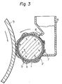
- a developer component 3 comprising particles of a dispersion of a magnetic powder in a binder medium having a particle size of 5 to 50 pm is combined with an earing promoting component 4 comprising sintered ferrite particles having a particle size of 20 to 100 1 1m to form a magnetic brush on the sleeve 2.
- this earing promoting component 4 is composed solely of sintered ferrite particles, this component 4 is excellent over the developer component 3 comprising a dispersion of a magnetic powder in a binder medium in the magnetic properties, and therefore, the component 4 has a function of maintaining good earing of the magnetic brush.
- a magnetic developer comprises a binder medium
- the flowability is reduced with elevation of the temperature and blocking is caused in an extreme case.
- This reduction of the flowability or occurrence of blocking results in reduction of the earing amount of the magnetic brush, and reduction of the image quality due to blurring or formation of white lines is caused.
- Reduction of the flowability or occurrence of blocking is caused by dewing on the surfaces of the developer particles as well as by elevation of the temperature.
- the ear promoting component of the present invention is incorporated, good earing is always maintained in the magnetic brush irrespectively of such environmental changes, and reduction of the image quality due to blurring or formation of lines can effectively be controlled.
- the developer of the present invention is distinguishable from an ordinary two-component type magnetic developer because the developer component, that is, the toner, is composed of particles of a dispersion of a magnetic powder in a binder medium, and one of the important features of the present invention is that the earing promoting component is composed of sintered ferrite particles.
- the developer component used in the present invention exerts a developing action based on the balance between the magnetic attractive force to the sleeve and the electrostatic attractive force (Coulomb force) to the electrostatic latent image as well as an ordinary one-component type magnetic developer, and the developing function of the developer of the present invention is different from that of an ordinary two-component type developer because the threshold value at the development is determined irrespectively of the earing promoting component or carrier. Accordingly, in the developing method of the present invention, even if the weight ratio of the earing promoting component to the developer component is changed in a broad range of from 80/20 to 10/90, especially from 65/35 to 20/80, the density of the formed image is maintained at a substantially equal high level. This is one of the important features of the present invention. Table 1 given hereinafter indicates that even if the mixing ratio of both the components is changed in a broad range, the image density is maintained at a substantially equal high level.
- the earing promoting component should be composed of sintered ferrite particles.
- a known magnetic carrier (so-called iron powder carrier) has a residual magnetism of 10- 7 to 2X10⁻⁷ Weber/g (10 to 20 e.m.u./g) and a coercive force of 800 to 2400 A/m, (10 to 30 Oe), but the sintered ferrite particles used in the present invention have a residual magnetism of 0 to 10- 8 Weber/g (0 to 1.0 e.m.u./g) and a coercive force of 0 to 400 A/m (0 to 5 Oe).
- magentic toner is not readily separated from the surface of the carrier and a problem of reduction of the developing efficiency arises. This defect is similarly observed when particles formed by binding magnetite (Fe 3 0 4 ) with a resin are used as the earing promoting component.
- the earing promoting component since the residual magnetism and coercive force of this component are 1/10 to 1/20 of those of the conventional magnetic carrier, the earing promoting component is effective for forming a magnetic brush of good earing but the earing promoting component per se is not magnetized, and therefore, a good developing efficiency is attained.
- the particle size of the sintered ferrite particles is smaller than 20 microns, it is difficult to maintain good earing of the magnetic brush, and if the particle size of the sintered ferrite particles exceeds 100 microns, scratches ordinarily called "brush marks" are often formed in the obtained toner image.
- the sintered ferrite particles used in the present invention are known.
- Sintered ferrite particles composed of manganese zinc iron oxide are especially preferred for attaining the objects of the present invention.
- the shape of the sintered ferrite particles is not particularly critical, but spherical sintered particles are advantageously used. Of course, sintered particles having an indeterminate shape can be used.
- the developer component used in the present invention comprises particles of a dispersion of a magnetic powder in a binder medium.
- the composition and preparation process may be the same as those of the known one-component type magnetic developer.
- a resin having a fixing property under heat or pressure is used as the binder medium.
- a thermoplastic resin or an uncured product or precondensate of a thermosetting resin may be used.
- Valuable natural resins are balsam, rosin, shellac and copal. These natural resins may be modified with at least one member selected from vinyl resins, acrylic resins, alkyd resins, phenolic resins, epoxy resins and oleoresins as described below.
- vinyl resins such as vinyl chloride resins, vinylidene chloride resins, vinyl acetate resins, vinyl acetal resins, e.g., polyvinyl butyral, and vinyl ether polymers, acrylic resins such as polyacrylic acid esters, polymethacrylic acid esters, acrylic acid copolymers and methacrylic acid copolymers, olefin type resins such as polyethylene and polypropylene, styrene type resins such as polystyrene, hydrogenated styrene resins, polyvinyl toluene and styrene copolymers, polyamide resins such as nylon 12, nylon 6 and polymerized fatty acid modified polyamides, polyesters such as polyethylene terephthalate/isophthalate and polytetramethylene terephthalate/isophthalate, alkyd resins such as phthalic acid resins and maleic acid resins,
- vinyl resins such as vinyl chloride resins, vinylidene
- a wax may be used as the binder medium.
- waxes in a narrow sense such as carnauba wax, cotton wax, candelilla wax, sugar cane wax, bees wax and wool wax, mineral waxes such as montan wax, paraffin wax and microcrystalline wax, solid higher fatty acids having 16 to 22 carbon atoms such as palmitic acid, stearic acid, hydroxystearic acid and behenic acid, amides of higher fatty acids having 16 to 22 carbon atoms (by the term "higher” given hereinafter is meant "having 16 to 22 carbon atoms”) such as oleic acid amide, stearic acid amide, palmitic acid amide, N - hydroxyethyl - hydroxystearoamide, N,N' - ethylene - bis - stearoamide, N,N' - ethylene - bis - ricinolamide and N,N' - ethylene - bis - hydroxystearylamide,
- the magnetic powder there may be used magnetite (Fe 3 0 4 ), y-diiron trioxide (y-Fe 2 0 3 ), and magnetic materials mentioned above with respect to the earing promoting component.
- the amount of the magnetic powder in the particles of the developer component be 40 to 75% by weight based on the sum of the binder medium and magnetic powder.
- the developer component of the present invention may be used in the form of a so-called conductive magnetic developer.
- a conducting agent such as carbon black is incorporated in the particles of the developer component or a conducting agent such as carbon black is scattered or further embedded onto the surfaces of the particles of the developer component, so that the resistivity of the developer component is 10 4 to 10" Q-cm.
- charging of the particles of the developer component is effected by dielectric polarization, and development becomes possible.
- the developer component of the present invention may be used in the form of an insulating magnetic developer.
- the resistivity of the developer component is adjusted to a level higher than 10 13 Q-cm.
- a known negative or positive charge controlling agent may be blended.
- granulation can easily be accomplished by melt-kneading the respective ingredients, cooling the kneaded mixture and pulverizing it. Furthermore, a granulation product can be prepared by dispersing the magnetic powder in a resin solution and spray-granulating the dispersion.
- the shape of the particles is not particularly critical, and the particles may have a spherical shape, an indeterminate shape or a slightly rounded indeterminate shape.
- the earing promoting component and the developer component may be present on the sleeve at a weight ratio of from 80/20 to 10/90, especially from 65/35 to 20/80.
- the earing promoting component may always be held on the sleeve without isolation therefrom, or there may be adopted a method in which the earing promoting component is once isolated from the sleeve and is supplied onto the sleeve again.
- the developer component is packed in a developer vessel and is supplied onto the sleeve, and the developer-supplying operation is carried out in the same manner as in case of an ordinary one-component type developer and the supplying operation is facilitated.
- the flowability is further improved and prevention of blocking becomes more complete.
- a method for developing electrostatic latent images wherein a developer-delivering sleeve having a magnet disposed in the interior thereof is arranged between the surface of a photosensitive drum having an electrostatic latent image formed thereon and a developer vessel packed only with the developer component, a magnetic brush is formed on the sleeve the earing promoting component comprising sintered ferrite particles having a particle size of 20 to 100 pm and the developer component comprising particles of a dispersion of a magnetic powder in a binder medium having a particle size of 5 to 50 ⁇ m,and at least one of the sleeve and the magnet disposed in the interior thereof is rotated.
- a developer-delivering sleeve 2 provided with a magnet 1 is arranged between the surface of a photosensitive drum 5 having an electrostatic latent image formed thereon and a vessel 6 for containing only the developer component 3 therein.
- the magnet 1 has a symmetric multi-polar structure having poles S and N arranged alternately along the inner circumference of the sleeve, and the sleeve 2 is fixed but the internal magnet 1 is rotatably arranged.
- the photosensitive drum 5 is rotated in the clockwise direction and the magnet 1 is rotated in the same direction, that is, the clockwise direction.
- the earing promoting component 4 and developer component 3 are moved, while being rotated, along the surface of the sleeve in the direction opposite to the rotation direction of the magnet 1, and good earing is attained according to the above-mentioned mechanism.
- the electrostatic latent image is frictionally contacted with the so-formed magnetic brush and the latent image is developed by the developer component.
- an ear cutting plate 8 is arranged to adjust the earing quantity.
- the magnet 1 within the sleeve 2 be driven and rotated and the sleeve 2 be stopped or rotated.
- the magnet 1 in order to deliver the developer, it is necessary to rotate the sleeve 2.
- mixing of the earing promoting component and the developer component is likely to be uneven.
- the magnet is rotated according to this embodiment of the present invention, uniform mixing of the earing promoting component and the developer component is always maintained on the sleeve, and good and uniform earing is always attained on the sleeve.
- the moving speed of the photosensitive drum is 20 to 60 rotations per minute, and the moving speed of the magnet is 500 to 1000 rotations per minute.
- the sleeve 2 is rotatably arranged, and the sleeve 2 is rotated in the direction reverse to the rotation direction of the magnet 1, that is, in the counterclockwise direction, whereby the moving speed of the developer as a whole can be increased.
- the stirring action is enhanced and earing is more improved and uniformalized.
- the moving speed of the magnet 1 is 500 to 1000 rotations per minute, and the moving speed of the sleeve is 100 to 400 rotations per minute.
- a method for developing electrostatic latent images wherein a developer-delivering sleeve having a magnet disposed in the interior thereof is arranged between the surface of a photosensitive drum having an electrostatic latent image formed thereon and a developer vessel for containing only a developer component therein, a magnetic brush is formed on the sleeve with an earing promoting component comprising sintered ferrite particles having a particle size of 20 to 100 11m and a developer component comprising particles of a dispersion of a magnetic powder in a binder medium having a particle size of 5 to 50 pm, the sleeve is rotated, and an asymmetric magnet comprising poles S and N arranged alternately along the inner circumference of the sleeve but also comprising adjacent poles S or N at a position other than the developer supply zone is arranged and fixed in the sleeve.
- a method for developing electrostatic latent images wherein a developer-delivering sleeve having a magnet disposed in the interior thereof is arranged between the surface of a photosensitive drum having an electrostatic latent image formed thereon and a developer vessel for containing a developer therein, a magnetic brush is formed on the sleeve with an earing promoting component comprising sintered ferrite particles having a particle size of 20 to 100 11 m and a developer component comprising particles of a dispersion of a magnetic powder in a binder medium having a particle size of 5 to 50 11m, the sleeve is rotated, and a magnet comprising poles S and N arranged alternately along the inner circumference of the sleeve and having a non-magnetized portion in at least a part of the developer vessel is arranged and fixed in the sleeve.
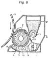
- the arrangement of the photosensitive drum, sleeve and developer vessel is substantially the same as in the embodiment shown in Fig. 3 except that as in the embodiment shown in Fig. 5, the sleeve 2 is rotatably arranged but the magnet 1b is fixed.
- This magnet 1b is characterized in that poles S and N are arranged alternately along the inner circumference of the sleeve but the magnet 1b has a non-magnetized portion 9 in at least a part of the developer vessel.
- the magnetic brush which has performed the developing operation is easily scraped from the sleeve 2 into the developer vessel 6 by the scraping plate 10 in the non-magnetized portion 9 of the magnet 1, and the earing promoting component 4 and developer component 3 are uniformly stirred and they are supplied onto the sleeve 2 again in the form of a homogeneous mixture, whereby separation of the earing promoting component 4 from the developer component 3 is effectively controlled.
- the rotation speed of the sleeve may be the same as in the embodiment illustrated in Fig. 5.
- a mixture of the above-mentioned earing promoting component 20 and developer component 21 is supplied to the concentrated parallel magnetic field region 22 of the delivering sleeve 17, and the mixture is disentangled in this region 22 so that the density is coarsened. If the mixture of the earing promoting component 20 and developer component 21 is thus disentangled in the density-coarsened state, the earing promoting component is always held on the sleeve 17, and even if the developer component 21 is supplied onto this earing promoting component 20, mixing and stirring of both the components can be accomplished uniformly and very effectively without compression of the particles, with the result that the toner particles can be charged effectively and blocking of the toner particles can be prevented. This stirring with no compressive force can be accomplished only when both the components are passed through the concentrated parallel magnetic field region between the magnetic pole in the sleeve and the magnetic material 23.
- the magnetic brush 19 is magnified by the earing promoting mechanism 23 as a magnetic magnifying glass and this magnified magnetic brush 19 is cut by the non-magnetic ear cutting mechanism 16, very high precision cutting of the magnetic brush, that is, high precision ear cutting, can be accomplished. Therefore, according to this embodiment of the present invention, an image having a uniform density can be formed stably along the entire surface of the photosensitive drum 5.
- the earing promoting mechanism 23 may be formed of an optional magnetic material, for example, a soft iron plate, a steel plate, a sintered ferrite plate, a nickel plate or a cobalt plate. In order to maintain good and uniform earing while preventing the waving phenomenon, it is preferred that the thickness of the earing promoting mechanism be in the range of from 0.5 to 5 mm.
- the ear cutting mechanism 16 may be formed of an optional non-magnetic material, for example, brass, phosphor bronze, aluminum, duralumin, non-magnetic stainless steel, various ceramic materials, glass or plastics.
- the magnet 18 be fixed and the sleeve 17 be rotated and delivery and cutting of the magnetic be performed in this state.
- the earing promoting mechanism 23 is arranged to confront the magnetic poles of the magnet 18.
- the magnetic brush 19 is moved in the same direction as the rotation direction of the sleeve.
- this embodiment may also be applied to the method where the magnet is rotated and the sleeve is fixed and the method where both the magnet and the sleeve are simultaneously rotated, and advantages as described above can similarly be attained.
- the earing promoting mechanism 23 composed of a magnetic material be arranged in the positional relation shown in Fig. 7, but of course, the arrangement of the mechanism 23 is not limited to that shown in Fig. 7.
- the earing promoting mechanism 23 is arranged on the magnetic brush return side of the developer vessel as shown in Fig. 9, and a modification in which the earing promoting mechanism 23 is arranged on the magnetic brush discharge side of the ear cutting mechanism 16 as shown in Fig. 10.
- magtic toner The preparation of the magnetic developer component (magnetic toner) will first be described.
- a starting material comprising 45 parts by weight of Arcon P-125 (hydrogenated styrene resin supplied by Arakawa Rinsan Kagaku Kogyo K.K.), 10 parts by weight of Migrosine stearate (salt of 1 part by weight of Migrosine Base with 4 parts by weight of stearic acid), 25 parts by weight of Amide AP-1 (fatty acid amide having a melting point of 98°C, supplied by Nippon Kasei K.K.), 20 parts by weight of Evaflex 420 (ethylene-vinyl acetate copolymer supplied by Mitsui Polychemical K.K).
- Arcon P-125 hydrogenated styrene resin supplied by Arakawa Rinsan Kagaku Kogyo K.K.
- Migrosine stearate salt of 1 part by weight of Migrosine Base with 4 parts by weight of stearic acid
- Amide AP-1 fatty acid amide having a melting point of 98°C, supplied by Nippo
- the particles (100 parts by weight) were homogeneously mixed with 0.5 part by weight of Printex L (carbon black) and 0.3 part by weight of Aerosil R972 (finely divided silica) by a Henschal mixer to form a conductive magnetic toner (1).
- the resistivity of the toner particles. was 10 8 Q-cm.
- a starting material comprising 14 parts by weight of Pliolite ACL (styrene-acrylic copolymer supplied by Goodyear Co.), 31 parts by weight of Hi-Wax 200P (polyethylene wax supplied by Mitsui Polychemical K.K.) and 55 parts by weight of Magnetic Iron Oxide RB-BL (triiron tetroxide supplied by Titan Kogyo K.K.) was melted and kneaded by using a hot three-roll mill and was then cooled and finely pulverized by a jet mill. The pulverization product was classified by an air classifying apparatus supplied by Alpine Co. to obtain particles having a particle size of 5 to 15 ⁇ m.
- Pliolite ACL styrene-acrylic copolymer supplied by Goodyear Co.
- Hi-Wax 200P polyethylene wax supplied by Mitsui Polychemical K.K.
- Magnetic Iron Oxide RB-BL triiron tetroxide supplied by Titan Kogyo K.K.
- a starting material comprising 40 parts by weight of Pliolite ACL, 5 parts by weight of Viscol 550P and Iron Black B6 was melted and kneaded by a hot three-roll mill and then cooled and finely pulverized by a jet mill. Particles having 5 to 15 11m were recovered by using an air classifying apparatus supplied by Alpine Co.
- a developer comprising 150 g of sintered ferrite particles having a particle size of 53 to 96 ⁇ m and 250 g of the magnetic toner (3) was caused to uniformly ear on a sleeve of a developing apparatus, and 250 g of the magnetic toner (3) as the reserve toner was charged in a hopper and 30000 prints were continuously formed in a chamber maintained at 35 to 38°C in the state where the developing bias was cut.
- the concentration of the magnetic toner on the sleeve was 63%. There was found no difference of the image density, fogging of the background or the image uniformity between the first print and the 30000th print, and a good image was stably formed on the 30000th print. After formation of 30000 prints, the magnetic toner concentration on the sleeve was 63%.
- the developing bias was cut and the copying operation was carried out by using the magnetic toner (3) alone.
- the image density was high at the start of the copying operation, but when 100 prints were continuously formed, removal of the untransferred toner on the drum was insufficient and the entire drum was stained black with the toner, and no image was obtained.
- Example 4 the weight ratio between the sintered ferrite particles and the developer component was changed, and the relation between the concentration of the developer component and the image density was examined. The obtained results are shown in Table 1.
- the image densities and fog densities of copies obtained in Examples 1 through 4 and Comparative Examples 1 through 5 are shown in Table 2. Incidentally, the density was measured by using Sakura Densitometer PDA65 (supplied by Konishiroku Shashin Kogyo K.K.).
- a developing apparatus of the type shown in Fig. 7 in which both the sleeve and magnet were rotated and a magnetic plate was attached on the toner hopper side of a non-magnetic ear cutting plate, 5 g of an earing promoting component comprising sintered ferrite particles of the manganese zinc iron oxide type (MFC-3 supplied by TDK Co. and having an average particle size of 40 ⁇ m and a particle size distribution of 23 to 53 um) was caused to uniformly ear on the sleeve, and a homogeneous mixture of 100 g of the magnetic toner (3) and 0.1 g of paper powder was charged in the hopper.
- the developing apparatus was set in a copying machine of the pressure fixation type and 10000 prints were continuously formed. There was found no difference of the image density, fogging of the background or the uniformity of the image quality between the first print and 10000th print, and a good image was stably formed in the 10000th print.
- Example 6 In the same apparatus as used in Example 6 except that the magnetic plate was not attached, the copying test was carried out in the same manner as in Example 6 by using 7 g of the same earing promoting component as used in Example 6 and a homogeneous mixture of 100 g of the magnetic toner (1) and 0.1 g of paper powder. When about 800 prints were formed, white lines appeared on the formed image. When the developing apparatus as examined, it was found that aggregates of paper powder were filled at the ear cutting plate to inhibit the delivery of the toner and bring about non-earing lines on the sleeve.
- Example 7 In the same developing apparatus as used in Example 7 except that the magnetic plate was not attached, the copying test was carried out in the same manner as described in Example 7 by using 5 g of the earing promoting component used in Example 7 and a homogeneous mixture of 100 g of the magnetic toner (3) and 0.1 g of paper powder.
- the uniformity of the image quality was reduced though no change was seen at first sight. Namely, although white lines were not observed, longitudinal lines slightly differing in the density were found, and when earing of the toner on the sleeve was examined, there locally appeared portions of a low toner density (high earing promoting component concentration), which formed the above-mentioned lines on the sleeve.
- the image densities (the density of the image area corresponding to the shear black portion having a side of 2 cm in the original) and fog densities (the density of the non-image area) of the copies obtained in Examples 5 through 7 and Comparative Examples 6 through 9 are shown in Table 3.
- the density was measured by using Sakura Densitometer PDA 65 (supplied by Konishiroku Shashin Kogyo K.K.).
Landscapes
- Physics & Mathematics (AREA)
- General Physics & Mathematics (AREA)
- Developing Agents For Electrophotography (AREA)
- Magnetic Brush Developing In Electrophotography (AREA)
Claims (7)
Applications Claiming Priority (4)
| Application Number | Priority Date | Filing Date | Title |
|---|---|---|---|
| JP14988882A JPS5940653A (ja) | 1982-08-31 | 1982-08-31 | 静電像の現像方法 |
| JP149888/82 | 1982-08-31 | ||
| JP184730/82 | 1982-10-22 | ||
| JP18473082A JPS5975269A (ja) | 1982-10-22 | 1982-10-22 | 静電像の磁気ブラシ現像法 |
Publications (3)
| Publication Number | Publication Date |
|---|---|
| EP0106465A2 EP0106465A2 (fr) | 1984-04-25 |
| EP0106465A3 EP0106465A3 (en) | 1985-11-13 |
| EP0106465B1 true EP0106465B1 (fr) | 1989-04-26 |
Family
ID=26479649
Family Applications (1)
| Application Number | Title | Priority Date | Filing Date |
|---|---|---|---|
| EP19830304975 Expired EP0106465B1 (fr) | 1982-08-31 | 1983-08-30 | Méthode de développement d'images latentes électrostatiques |
Country Status (3)
| Country | Link |
|---|---|
| EP (1) | EP0106465B1 (fr) |
| CA (1) | CA1204030A (fr) |
| DE (1) | DE3379747D1 (fr) |
Families Citing this family (2)
| Publication number | Priority date | Publication date | Assignee | Title |
|---|---|---|---|---|
| EP0332428B1 (fr) * | 1988-03-10 | 1994-07-06 | Canon Kabushiki Kaisha | Procédé pour la formation d'une image |
| US6691273B2 (en) | 2001-01-17 | 2004-02-10 | Telefonaktiebolaget Lm Ericsson (Publ) | Error correction using packet combining during soft handover |
Family Cites Families (7)
| Publication number | Priority date | Publication date | Assignee | Title |
|---|---|---|---|---|
| BE610591A (fr) * | ||||
| US2846333A (en) * | 1955-11-01 | 1958-08-05 | Haloid Xerox Inc | Method of developing electrostatic images |
| JPS5646596B2 (fr) * | 1974-08-28 | 1981-11-04 | ||
| US4331757A (en) * | 1976-12-29 | 1982-05-25 | Minolta Camera Kabushiki Kaisha | Dry process developing method and device employed therefore |
| US4294904A (en) * | 1979-11-21 | 1981-10-13 | Xerox Corporation | Inductive development materials for a magnetic development process |
| JPS5726878A (en) * | 1980-07-23 | 1982-02-13 | Mita Ind Co Ltd | Display device for remaining amount of two component type developer |
| JPS57155553A (en) * | 1981-03-23 | 1982-09-25 | Mita Ind Co Ltd | Electrostatic image developing method |
-
1983
- 1983-08-30 CA CA000435679A patent/CA1204030A/fr not_active Expired
- 1983-08-30 DE DE8383304975T patent/DE3379747D1/de not_active Expired
- 1983-08-30 EP EP19830304975 patent/EP0106465B1/fr not_active Expired
Also Published As
| Publication number | Publication date |
|---|---|
| CA1204030A (fr) | 1986-05-06 |
| EP0106465A2 (fr) | 1984-04-25 |
| EP0106465A3 (en) | 1985-11-13 |
| DE3379747D1 (en) | 1989-06-01 |
Similar Documents
| Publication | Publication Date | Title |
|---|---|---|
| EP0062445B1 (fr) | Procédé de développement d'images électrostatiques | |
| US4517274A (en) | Method for developing electrostatic latent images | |
| JPH0121505B2 (fr) | ||
| EP0183509B1 (fr) | Méthode de développement par brosse magnétique | |
| JPH0648399B2 (ja) | 静電像の現像方法 | |
| US5359147A (en) | Electrostatic latent image developer | |
| JPH0232622B2 (fr) | ||
| EP0106465A2 (fr) | Méthode de développement d'images latentes électrostatiques | |
| US4294904A (en) | Inductive development materials for a magnetic development process | |
| JPH0366666B2 (fr) | ||
| US5629119A (en) | Magnetic carrier for electrophotographic developing agent | |
| JPH0428106B2 (fr) | ||
| US5532095A (en) | Magnetic toner | |
| JPH0381145B2 (fr) | ||
| JP3010917B2 (ja) | 絶縁性磁性1成分トナーの現像方法 | |
| JPH024281A (ja) | 磁性キャリア | |
| JPH08314280A (ja) | 現像方法 | |
| JPH0257302B2 (fr) | ||
| JP3047073B2 (ja) | 高濃度現像方法 | |
| JPS5940653A (ja) | 静電像の現像方法 | |
| JPH0115062B2 (fr) | ||
| JPH0623868B2 (ja) | 反転現像方法 | |
| JPH0876482A (ja) | 二成分系現像剤 | |
| JPH0876446A (ja) | 二成分系現像剤 | |
| JPH04288555A (ja) | 磁性現像剤 |
Legal Events
| Date | Code | Title | Description |
|---|---|---|---|
| PUAI | Public reference made under article 153(3) epc to a published international application that has entered the european phase |
Free format text: ORIGINAL CODE: 0009012 |
|
| AK | Designated contracting states |
Designated state(s): DE FR GB IT NL |
|
| PUAL | Search report despatched |
Free format text: ORIGINAL CODE: 0009013 |
|
| AK | Designated contracting states |
Designated state(s): DE FR GB IT NL |
|
| 17P | Request for examination filed |
Effective date: 19860317 |
|
| 17Q | First examination report despatched |
Effective date: 19870424 |
|
| ITF | It: translation for a ep patent filed | ||
| GRAA | (expected) grant |
Free format text: ORIGINAL CODE: 0009210 |
|
| AK | Designated contracting states |
Kind code of ref document: B1 Designated state(s): DE FR GB IT NL |
|
| REF | Corresponds to: |
Ref document number: 3379747 Country of ref document: DE Date of ref document: 19890601 |
|
| ET | Fr: translation filed | ||
| PLBE | No opposition filed within time limit |
Free format text: ORIGINAL CODE: 0009261 |
|
| STAA | Information on the status of an ep patent application or granted ep patent |
Free format text: STATUS: NO OPPOSITION FILED WITHIN TIME LIMIT |
|
| 26N | No opposition filed | ||
| ITTA | It: last paid annual fee | ||
| PGFP | Annual fee paid to national office [announced via postgrant information from national office to epo] |
Ref country code: GB Payment date: 19970821 Year of fee payment: 15 |
|
| PGFP | Annual fee paid to national office [announced via postgrant information from national office to epo] |
Ref country code: DE Payment date: 19970905 Year of fee payment: 15 |
|
| PGFP | Annual fee paid to national office [announced via postgrant information from national office to epo] |
Ref country code: FR Payment date: 19980814 Year of fee payment: 16 |
|
| PGFP | Annual fee paid to national office [announced via postgrant information from national office to epo] |
Ref country code: NL Payment date: 19980827 Year of fee payment: 16 |
|
| PG25 | Lapsed in a contracting state [announced via postgrant information from national office to epo] |
Ref country code: GB Free format text: LAPSE BECAUSE OF NON-PAYMENT OF DUE FEES Effective date: 19980830 |
|
| GBPC | Gb: european patent ceased through non-payment of renewal fee |
Effective date: 19980830 |
|
| PG25 | Lapsed in a contracting state [announced via postgrant information from national office to epo] |
Ref country code: DE Free format text: LAPSE BECAUSE OF NON-PAYMENT OF DUE FEES Effective date: 19990601 |
|
| PG25 | Lapsed in a contracting state [announced via postgrant information from national office to epo] |
Ref country code: NL Free format text: LAPSE BECAUSE OF NON-PAYMENT OF DUE FEES Effective date: 20000301 |
|
| PG25 | Lapsed in a contracting state [announced via postgrant information from national office to epo] |
Ref country code: FR Free format text: LAPSE BECAUSE OF NON-PAYMENT OF DUE FEES Effective date: 20000428 |
|
| NLV4 | Nl: lapsed or anulled due to non-payment of the annual fee |
Effective date: 20000301 |
|
| REG | Reference to a national code |
Ref country code: FR Ref legal event code: ST |