EP0106480A2 - Ailettes de refroidissement pour échangeurs de chaleur - Google Patents
Ailettes de refroidissement pour échangeurs de chaleur Download PDFInfo
- Publication number
- EP0106480A2 EP0106480A2 EP83305076A EP83305076A EP0106480A2 EP 0106480 A2 EP0106480 A2 EP 0106480A2 EP 83305076 A EP83305076 A EP 83305076A EP 83305076 A EP83305076 A EP 83305076A EP 0106480 A2 EP0106480 A2 EP 0106480A2
- Authority
- EP
- European Patent Office
- Prior art keywords
- strip
- cooling fins
- rolls
- projections
- self
- Prior art date
- Legal status (The legal status is an assumption and is not a legal conclusion. Google has not performed a legal analysis and makes no representation as to the accuracy of the status listed.)
- Withdrawn
Links
- 238000001816 cooling Methods 0.000 title claims abstract description 17
- 239000000463 material Substances 0.000 claims description 7
- 238000004519 manufacturing process Methods 0.000 claims description 6
- 238000000926 separation method Methods 0.000 claims 1
- 229910000881 Cu alloy Inorganic materials 0.000 abstract description 3
- 238000000034 method Methods 0.000 description 3
- 230000002093 peripheral effect Effects 0.000 description 2
- 238000005452 bending Methods 0.000 description 1
- 238000007664 blowing Methods 0.000 description 1
Images


Classifications
-
- F—MECHANICAL ENGINEERING; LIGHTING; HEATING; WEAPONS; BLASTING
- F28—HEAT EXCHANGE IN GENERAL
- F28F—DETAILS OF HEAT-EXCHANGE AND HEAT-TRANSFER APPARATUS, OF GENERAL APPLICATION
- F28F1/00—Tubular elements; Assemblies of tubular elements
- F28F1/10—Tubular elements and assemblies thereof with means for increasing heat-transfer area, e.g. with fins, with projections, with recesses
- F28F1/12—Tubular elements and assemblies thereof with means for increasing heat-transfer area, e.g. with fins, with projections, with recesses the means being only outside the tubular element
- F28F1/24—Tubular elements and assemblies thereof with means for increasing heat-transfer area, e.g. with fins, with projections, with recesses the means being only outside the tubular element and extending transversely
- F28F1/32—Tubular elements and assemblies thereof with means for increasing heat-transfer area, e.g. with fins, with projections, with recesses the means being only outside the tubular element and extending transversely the means having portions engaging further tubular elements
- F28F1/325—Fins with openings
-
- B—PERFORMING OPERATIONS; TRANSPORTING
- B21—MECHANICAL METAL-WORKING WITHOUT ESSENTIALLY REMOVING MATERIAL; PUNCHING METAL
- B21D—WORKING OR PROCESSING OF SHEET METAL OR METAL TUBES, RODS OR PROFILES WITHOUT ESSENTIALLY REMOVING MATERIAL; PUNCHING METAL
- B21D13/00—Corrugating sheet metal, rods or profiles; Bending sheet metal, rods or profiles into wave form
- B21D13/04—Corrugating sheet metal, rods or profiles; Bending sheet metal, rods or profiles into wave form by rolling
-
- B—PERFORMING OPERATIONS; TRANSPORTING
- B21—MECHANICAL METAL-WORKING WITHOUT ESSENTIALLY REMOVING MATERIAL; PUNCHING METAL
- B21D—WORKING OR PROCESSING OF SHEET METAL OR METAL TUBES, RODS OR PROFILES WITHOUT ESSENTIALLY REMOVING MATERIAL; PUNCHING METAL
- B21D53/00—Making other particular articles
- B21D53/02—Making other particular articles heat exchangers or parts thereof, e.g. radiators, condensers fins, headers
- B21D53/022—Making the fins
- B21D53/025—Louvered fins
-
- F—MECHANICAL ENGINEERING; LIGHTING; HEATING; WEAPONS; BLASTING
- F28—HEAT EXCHANGE IN GENERAL
- F28F—DETAILS OF HEAT-EXCHANGE AND HEAT-TRANSFER APPARATUS, OF GENERAL APPLICATION
- F28F2215/00—Fins
- F28F2215/12—Fins with U-shaped slots for laterally inserting conduits
Definitions
- This invention relates to cooling fins for heat exchangers, and especially to heat exchanger qomprising tubes in contact with the fins.
- Such heat exchangers commonly include a multiplicity of tubes, often arranged in rows, which pass through openings, which may be either holes or slots in the side edges, in fins arranged in a stack in plaoes at right angles to the tube axes.
- the fins act as secondary cooling surfaces to the primary cooling surfaces provided by the tubes.
- Fin spacing is achieved by interpreting elements between the fins to hold them apart.
- the spacing members often take the form of tabs raised out of the material of the fins themselves, and are arranged to contact the surface of an adjacent fin to ensure a gap between it and the fin from which tha spacing member is raised.
- Such cooling fins are known as self-stacking cooling fins.
- Each of the fins in the stack is a separate member.
- One method of manufacture is for strip material to be rolled to produce the necessary openings and raised portions, and then cut into the required lengths. Then the fins can be inserted in the stack.
- a sheet of fin stock is repeatedly perforated across its width along closely spaced lines which are spaced apart by the desired fin width: the sheet is then folded zig-zag fashion along the perforations to form the stack of fin elements. Projections raised out of the stock are on opposite sides for each adjacent fin width in order to space the fins when the stack is formed.
- the invention provides self-stacking cooling fins for a heat exchanger comprising a strip having an alternating series of first and second portions, the first portions having projections upstanding from one side of the strip and the second portions having projections upstanding from the other side of the strip, the strip being folded between the first and the second portions in zig-zag fashion so that the projections extend in the same direction and space successive portions of the strip from each other.
- the fold regions are at the ends of the stack and do not impede the air flow through the stack.
- the fold regions lie between adjacent fins and across the whole face of the stack, and these do impede air flow thraugh the stack.
- the projections have been formed by feeding the strip material between a pair of rolls having shaped peripheries.
- one first portion and one second portion were formed during one revolution of the rolls.
- the rolls co-operate with each other such that over one half of their peripheral surfaces, projections are raised from one side of the strip, and over the other half of their peripheral surfaces, projections are raised from the opposite side of the strip.
- any even number of alternating regions could be provided at the roll periphery.
- the invention also provides apparatus for and a method of manufacturing self-stacking cooling fins according to the invention.
- a strip 31 of plain copper alloy is fed between two forming rolls 34,35, and emerges into a hopper 36 bent in zig-zag fashion.
- this shows the formed strip as it would appear if laid out flat: it will be appreciated however that the strip will not actually take up this shape in practice, but will actually be as shown in Figure 3.
- the strip 11 consists of successive portions .12 and 13.
- the portions 12 have projections upstanding from the upper side of the strip, as is apparent by reference to Figure 2.
- the portions13 have projections upstanding from the lower side of the strip, but in other respects the projections are identical to those in the portions 12.
- openings 15 formed in each side are staggered with respect to each other, so that the stacked fins can accommodate two rows of flat tubes offset with respect to each other in the heat exchanger.
- the material displaced out of the openings form projections 15a.
- louvres 21 formed by piercing the strip along parallel lines and bending the material up to form the louvres. Beyond the louvres 21, the strip has apertures 14.
- the material displaced in forming the apertures 14 forms two projecting flaps 14a, 14b. These flaps are the subject of our co-pending British Patent Application No 82 0457.
- the louvres 21 and the flaps 14a, 14b assist in creating turbulence in the in the air passing through the heat exchanger of which the fins form a part, and hence promote better heat transfer to the air.
- the succession of staggered openings 15, louvres 21 and apertures 14 is repeated along the length of the fin.
- two folds 22, 23 are produced by the forming rolls. As is shown in Figure 3, an approximately 90° fold is produced at each line 22, 23, and the region 24 between the fold thus acts as a spacing member assisting the spacing of successive fins.
- the portions 13 are the same as the portions 12, but the projections 14a, 14b, 15a and 21 are on the underside of the strip instead of on the top side.
- the projections When the strip is folded in zig-zag fashion, the projections all point in the same direction, and the openings 15 overlie each other.
- the projections space adjacent fins from each other.
- plain copper alloy strip in a roll 32 is fed through a magazine 33 to a pair of forming rolls 34, 35.
- the strip is formed in the rolls and fed to a hopper 36 where it folds up in a stack.
- a guillotine 42 cuts the folded strip at intervals of time in order to produce suitable stacks of fin for heat exchangers.
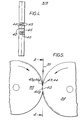
- Figure 5 shows an end wiew of the rolls but with the roll 35 rotated anticlockwise through 180° relative to the view of Figure 3.
- Figure 4 is an end view of roll 34 seen in the direction of the arrows 4-4.
- Projection 40 on roll 34 meshes with recess 40a to form fold lines 22,23. Clockwise from projection 40, the roll 34 has punches 43 for forming the openings 15 and punches 44 for forming the apertures 14, for one half the circumference of the roll 34 Equally, the roll 35 has a corresponding recess 43a and 44a for co-operating with the punches 43 and 44.
- the roll 34 At the half circumference position, the roll 34-has a recess 38 a which meshes with projection 38 to form folds 22, 23 but this time bent in the opposite sense to form the next fold of the zig-zag.
- the roll 34 has recesses which correspond to punches on the roll 35, in the order to form the projections on the other side of the strip to those produced by the first half-circumference.
- the rolls also have blades (not shown) for producing the louvre' 21.
- the rolls have small apertures 45 in their surface spaced around their entire circumferences for blowing the strip away from the rolls when it emerges below the nip pf the rolls.
- the stack of fins fed out of hopper 36 will have aligned openings 15, and flat tubes are slotted in from each side. Tube plates to form part of header tanks are added, and the parts are brazed together.
Landscapes
- Engineering & Computer Science (AREA)
- Mechanical Engineering (AREA)
- Physics & Mathematics (AREA)
- Geometry (AREA)
- Thermal Sciences (AREA)
- General Engineering & Computer Science (AREA)
- Heat-Exchange Devices With Radiators And Conduit Assemblies (AREA)
Applications Claiming Priority (2)
| Application Number | Priority Date | Filing Date | Title |
|---|---|---|---|
| GB8225864 | 1982-09-10 | ||
| GB8225864 | 1982-09-10 |
Publications (2)
| Publication Number | Publication Date |
|---|---|
| EP0106480A2 true EP0106480A2 (fr) | 1984-04-25 |
| EP0106480A3 EP0106480A3 (fr) | 1985-01-16 |
Family
ID=10532834
Family Applications (1)
| Application Number | Title | Priority Date | Filing Date |
|---|---|---|---|
| EP83305076A Withdrawn EP0106480A3 (fr) | 1982-09-10 | 1983-09-01 | Ailettes de refroidissement pour échangeurs de chaleur |
Country Status (3)
| Country | Link |
|---|---|
| EP (1) | EP0106480A3 (fr) |
| JP (1) | JPS59131887A (fr) |
| ES (1) | ES288245Y (fr) |
Cited By (2)
| Publication number | Priority date | Publication date | Assignee | Title |
|---|---|---|---|---|
| EP3306252A4 (fr) * | 2015-05-29 | 2018-05-09 | Mitsubishi Electric Corporation | Échangeur de chaleur et appareil à cycle de réfrigération |
| DE102017205147A1 (de) | 2017-03-27 | 2018-09-27 | Continental Automotive Gmbh | Verfahren zur Herstellung eines Wabenkörpers |
Families Citing this family (1)
| Publication number | Priority date | Publication date | Assignee | Title |
|---|---|---|---|---|
| US7488130B2 (en) * | 2007-02-01 | 2009-02-10 | Sanford, L.P. | Seal assembly for retractable instrument |
Family Cites Families (5)
| Publication number | Priority date | Publication date | Assignee | Title |
|---|---|---|---|---|
| US3167046A (en) * | 1956-01-24 | 1965-01-26 | Modine Mfg Co | Method of forming a sheet metal fin strip element for heat exchange structures |
| GB839333A (en) * | 1957-07-29 | 1960-06-29 | Richard Walker Kritzer | Improvements in heat transfer units |
| US3223153A (en) * | 1962-05-21 | 1965-12-14 | Modine Mfg Co | Fin and tube type heat exchanger |
| US3321014A (en) * | 1962-12-20 | 1967-05-23 | Borg Warner | Heat exchanger |
| EP0086559A3 (fr) * | 1982-02-16 | 1984-01-11 | Unipart Group Limited | Echangeurs de chaleur |
-
1983
- 1983-09-01 EP EP83305076A patent/EP0106480A3/fr not_active Withdrawn
- 1983-09-08 ES ES1983288245U patent/ES288245Y/es not_active Expired
- 1983-09-10 JP JP16737883A patent/JPS59131887A/ja active Pending
Cited By (5)
| Publication number | Priority date | Publication date | Assignee | Title |
|---|---|---|---|---|
| EP3306252A4 (fr) * | 2015-05-29 | 2018-05-09 | Mitsubishi Electric Corporation | Échangeur de chaleur et appareil à cycle de réfrigération |
| US10627175B2 (en) | 2015-05-29 | 2020-04-21 | Mitsubishi Electric Corporation | Heat exchanger and refrigeration cycle apparatus |
| DE102017205147A1 (de) | 2017-03-27 | 2018-09-27 | Continental Automotive Gmbh | Verfahren zur Herstellung eines Wabenkörpers |
| DE102017205147B4 (de) | 2017-03-27 | 2019-04-04 | Continental Automotive Gmbh | Verfahren zur Herstellung eines Wabenkörpers |
| US11131229B2 (en) | 2017-03-27 | 2021-09-28 | Vitesco Technologies GmbH | Method for producing a honeycomb body |
Also Published As
| Publication number | Publication date |
|---|---|
| JPS59131887A (ja) | 1984-07-28 |
| ES288245U (es) | 1986-06-01 |
| ES288245Y (es) | 1987-02-01 |
| EP0106480A3 (fr) | 1985-01-16 |
Similar Documents
| Publication | Publication Date | Title |
|---|---|---|
| EP0319451B1 (fr) | Echangeur de chaleur à ailettes sinusoidales perforées | |
| US6968891B2 (en) | Louver fin and corrugation cutter for forming louver fin | |
| CN102272547A (zh) | 用于热交换器的翅片和包括该翅片的热交换器 | |
| US5482115A (en) | Heat exchanger and plate fin therefor | |
| JP3974526B2 (ja) | ろう付け板を有する熱交換器 | |
| JPH0663710B2 (ja) | 一体構造のフィンユニットを備えた熱交換器及びその製造方法 | |
| JP2002228379A (ja) | 熱交換器のルーバーフィンおよびその熱交換器並びにそのルーバーフィンの組付け方法 | |
| EP1004370B1 (fr) | Procédé et appareil de profilage par roulage d'une pluralité de bandes métalliques pour échangeures de chaleur | |
| US20080047696A1 (en) | Heat transfer surfaces with flanged apertures | |
| US7004241B2 (en) | Flexible tube arrangement-heat exchanger design | |
| US4593756A (en) | Fin-and-tube type heat exchanger | |
| CN101341372A (zh) | 新型热交换器波纹及其应用 | |
| US20040031595A1 (en) | Method for producing an integrated heat exchanger and an integrated heat exchanger produced thereby | |
| US2856164A (en) | Heat exchanger | |
| US3266567A (en) | Heat exchanger | |
| DE69814020T2 (de) | Wärmetauscher und Verfahren zu dessen Herstellung | |
| EP0106480A2 (fr) | Ailettes de refroidissement pour échangeurs de chaleur | |
| US3273227A (en) | Fabrication of heat exchange devices | |
| US3292690A (en) | Heat exchangers | |
| US20050167088A1 (en) | Fin array for heat transfer assemblies and method of making same | |
| GB1471944A (en) | Heat exchangers | |
| DE602006000675T2 (de) | Wellrippe für integralgefertigten Wärmetäuscher | |
| EP2064509B1 (fr) | Surfaces de transfert de chaleur dotées d'ouvertures à brides | |
| US3309763A (en) | Method for making a heat exchanger | |
| JPH04270892A (ja) | 熱交換器 |
Legal Events
| Date | Code | Title | Description |
|---|---|---|---|
| PUAI | Public reference made under article 153(3) epc to a published international application that has entered the european phase |
Free format text: ORIGINAL CODE: 0009012 |
|
| AK | Designated contracting states |
Designated state(s): DE FR GB IT SE |
|
| PUAL | Search report despatched |
Free format text: ORIGINAL CODE: 0009013 |
|
| AK | Designated contracting states |
Designated state(s): DE FR GB IT SE |
|
| STAA | Information on the status of an ep patent application or granted ep patent |
Free format text: STATUS: THE APPLICATION IS DEEMED TO BE WITHDRAWN |
|
| 18D | Application deemed to be withdrawn |
Effective date: 19850917 |
|
| RIN1 | Information on inventor provided before grant (corrected) |
Inventor name: GEORGE, DAVID HEDLEY Inventor name: WILSON, CLIVE WINSTON |