EP2064509B1 - Surfaces de transfert de chaleur dotées d'ouvertures à brides - Google Patents
Surfaces de transfert de chaleur dotées d'ouvertures à brides Download PDFInfo
- Publication number
- EP2064509B1 EP2064509B1 EP07800510.5A EP07800510A EP2064509B1 EP 2064509 B1 EP2064509 B1 EP 2064509B1 EP 07800510 A EP07800510 A EP 07800510A EP 2064509 B1 EP2064509 B1 EP 2064509B1
- Authority
- EP
- European Patent Office
- Prior art keywords
- heat transfer
- transfer surface
- apertures
- flanges
- aperture
- Prior art date
- Legal status (The legal status is an assumption and is not a legal conclusion. Google has not performed a legal analysis and makes no representation as to the accuracy of the status listed.)
- Not-in-force
Links
- 230000002093 peripheral effect Effects 0.000 claims description 18
- 239000012530 fluid Substances 0.000 claims description 15
- 239000000463 material Substances 0.000 description 14
- 230000015572 biosynthetic process Effects 0.000 description 3
- 239000007788 liquid Substances 0.000 description 3
- 229910052782 aluminium Inorganic materials 0.000 description 2
- XAGFODPZIPBFFR-UHFFFAOYSA-N aluminium Chemical compound [Al] XAGFODPZIPBFFR-UHFFFAOYSA-N 0.000 description 2
- 230000003416 augmentation Effects 0.000 description 2
- 229910052751 metal Inorganic materials 0.000 description 2
- 239000002184 metal Substances 0.000 description 2
- 239000003921 oil Substances 0.000 description 2
- RYGMFSIKBFXOCR-UHFFFAOYSA-N Copper Chemical compound [Cu] RYGMFSIKBFXOCR-UHFFFAOYSA-N 0.000 description 1
- 238000010276 construction Methods 0.000 description 1
- 239000012809 cooling fluid Substances 0.000 description 1
- 229910052802 copper Inorganic materials 0.000 description 1
- 239000010949 copper Substances 0.000 description 1
- 229910003460 diamond Inorganic materials 0.000 description 1
- 239000010432 diamond Substances 0.000 description 1
- 230000001788 irregular Effects 0.000 description 1
- 238000004519 manufacturing process Methods 0.000 description 1
- 230000013011 mating Effects 0.000 description 1
- 238000000034 method Methods 0.000 description 1
- 238000012986 modification Methods 0.000 description 1
- 230000004048 modification Effects 0.000 description 1
- 229910001220 stainless steel Inorganic materials 0.000 description 1
- 239000010935 stainless steel Substances 0.000 description 1
Images


Classifications
-
- B—PERFORMING OPERATIONS; TRANSPORTING
- B23—MACHINE TOOLS; METAL-WORKING NOT OTHERWISE PROVIDED FOR
- B23P—METAL-WORKING NOT OTHERWISE PROVIDED FOR; COMBINED OPERATIONS; UNIVERSAL MACHINE TOOLS
- B23P15/00—Making specific metal objects by operations not covered by a single other subclass or a group in this subclass
- B23P15/26—Making specific metal objects by operations not covered by a single other subclass or a group in this subclass heat exchangers or the like
-
- B—PERFORMING OPERATIONS; TRANSPORTING
- B21—MECHANICAL METAL-WORKING WITHOUT ESSENTIALLY REMOVING MATERIAL; PUNCHING METAL
- B21D—WORKING OR PROCESSING OF SHEET METAL OR METAL TUBES, RODS OR PROFILES WITHOUT ESSENTIALLY REMOVING MATERIAL; PUNCHING METAL
- B21D53/00—Making other particular articles
- B21D53/02—Making other particular articles heat exchangers or parts thereof, e.g. radiators, condensers fins, headers
- B21D53/04—Making other particular articles heat exchangers or parts thereof, e.g. radiators, condensers fins, headers of sheet metal
-
- F—MECHANICAL ENGINEERING; LIGHTING; HEATING; WEAPONS; BLASTING
- F28—HEAT EXCHANGE IN GENERAL
- F28F—DETAILS OF HEAT-EXCHANGE AND HEAT-TRANSFER APPARATUS, OF GENERAL APPLICATION
- F28F1/00—Tubular elements; Assemblies of tubular elements
- F28F1/02—Tubular elements of cross-section which is non-circular
- F28F1/04—Tubular elements of cross-section which is non-circular polygonal, e.g. rectangular
-
- F—MECHANICAL ENGINEERING; LIGHTING; HEATING; WEAPONS; BLASTING
- F28—HEAT EXCHANGE IN GENERAL
- F28F—DETAILS OF HEAT-EXCHANGE AND HEAT-TRANSFER APPARATUS, OF GENERAL APPLICATION
- F28F1/00—Tubular elements; Assemblies of tubular elements
- F28F1/10—Tubular elements and assemblies thereof with means for increasing heat-transfer area, e.g. with fins, with projections, with recesses
- F28F1/40—Tubular elements and assemblies thereof with means for increasing heat-transfer area, e.g. with fins, with projections, with recesses the means being only inside the tubular element
-
- F—MECHANICAL ENGINEERING; LIGHTING; HEATING; WEAPONS; BLASTING
- F28—HEAT EXCHANGE IN GENERAL
- F28F—DETAILS OF HEAT-EXCHANGE AND HEAT-TRANSFER APPARATUS, OF GENERAL APPLICATION
- F28F13/00—Arrangements for modifying heat-transfer, e.g. increasing, decreasing
- F28F13/06—Arrangements for modifying heat-transfer, e.g. increasing, decreasing by affecting the pattern of flow of the heat-exchange media
- F28F13/12—Arrangements for modifying heat-transfer, e.g. increasing, decreasing by affecting the pattern of flow of the heat-exchange media by creating turbulence, e.g. by stirring, by increasing the force of circulation
Definitions
- This invention relates to heat exchangers, and in particular, to flow augmentation devices, such as fins, turbulizers or turbulators, used to increase heat transfer performance in heat exchangers.
- FIG. 4 Another type of turbulizer is shown in United States Patent No. 4,945,981 issued to Joshi .
- This patent shows the use of a louvered fin as a turbulizer. Louvered fins are commonly used on the air side of an air to liquid heat exchanger. In this Joshi patent, however, the louvered fin is located inside the heat exchanger tubes or channels that normally contain liquids, such as oils.
- CA 484 636 relates to a heat exchanger having spaced parallel metallic plates forming walls for a fluid flow passage with an undulated metallic plate disposed in the passage, the undulated plate having parallel rows of closely spaced rectangular perforations.
- the undulated plate is positioned within the fluid flow passage so that the crests and dwells thereof contact the walls of the fluid passage.
- Tab-like fins associated with each perforation extend from either side of the undulated surface which provides additional fin surface.
- the undulated plate is arranged within the heat exchanger so that flow through the heat exchanger is generally parallel to the longitudinal axis of the crests/dwells of the undulated plate.
- CA 484 636 does not disclose opposed peripheral edge portions of each of the perforations including respective flanges that extend outwardly from a single side of a planar fin forming said perforation, wherein the perforations are elongated, having a longitudinal axis extending in a direction transverse to the crests and wells of the udulated plate, and wherein the heat exchanger has a low pressure drop direction parallel to the planar fins and a high pressure drop direction transverse to the planar fins, the perforations being oriented in and the flanges extending in the high pressure drop direction.
- US 6,378,605 relates to a heat exchanger comprising a series of fins arranged external to the fluid flow conduits or tubes of the heat exchanger.
- the fins are formed with a plurality of piercings or perforations thereby forming a highly porous fin surface wherein the size of the apertures or perforations is relatively small with respect to the fin surface itself.
- the porous fins are arranged so as to be generally parallel to the flow of the cooling fluid, i.e. a gas, over the exterior of tube-like conduits, the perforations or piercings therefore being arranged generally perpendicular to the direction of fluid flow.
- US 6,378,605 does not disclose the fins being formed with spaced-apart apertures, wherein the apertures are elongated, having a longitudinal axis extending in a direction transverse to ridges formed by the fins, and wherein the heat exchanger has a low pressure drop direction parallel to the fins and a high pressure drop direction transverse to the fins, the piercings or perforations being oriented in and flanges formed by opposed peripheral edge portions of the piercings or perforations extending in the high pressure drop direction.
- corrugated heat transfer surfaces have a plurality of spaced-apart apertures with opposed peripheral edge portions which include transverse flanges to enhance heat transfer efficiency.
- a heat transfer surface for a heat exchanger comprising a corrugated member having parallel, spaced-apart ridges and planar fins extending therebetween.
- the planar fins are formed with spaced-apart apertures having opposed peripheral edge portions.
- the opposed peripheral edge portions of each aperture include respective flanges that extend outwardly from a single side of the planar fin forming said aperture.
- the apertures are elongated, having a longitudinal axis extending in a direction transverse to the ridges.
- the heat transfer surface has a low pressure drop direction parallel to the planar fins and a high pressure drop direction transverse to the planar fins, the apertures being oriented in and the flanges extending in the high pressure drop direction.
- a heat exchanger comprising a generally flat tube having first and second spaced-apart walls.
- a corrugated heat transfer surface is located in the tube.
- the heat transfer surface includes parallel, spaced-apart ridges with planar fins extending therebetween. Alternating ridges are in contact respectively with the first and second walls.
- the planar fins are formed with spaced-apart apertures having opposed peripheral edge portions. Also, the opposed peripheral edge portions of each aperture include respective flanges extending outwardly away from a single side of the planar fin forming said apertures.
- the tube has a longitudinal axis, the ridges of the heat transfer surface being oriented perpendicular to said longitudinal axis and flow through the tube being perpendicular to said ridges.
- the apertures are elongated, having a longitudinal axis extending in a direction transverse to the ridges and to the longitudinal flow direction the tube.
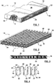
- Heat exchanger 10 consists of a single tube 12 containing a turbulizer or heat transfer surface 14, and as such, could be used to heat or cool one fluid flowing through tube 12 transferring heat to or from the ambient fluid surround tube 12. More likely, however, is that tube 12 would be a building block, such that a plurality of such tubes 12 would be stacked vertically in spaced-apart relationship with corrugated fins located between tubes 12.
- the open ends 16 at each end of tube 12 would either form a respective fluid inlet and outlet for the heat exchanger or would be attached to communicate with manifolds or headers (not shown) to supply fluid to a stack of tubes 12 and receive the fluid from them.
- Heat transfer surfaces 14 could also be attached to the outside surfaces of tubes 12, or located between stacked, spaced-apart tubes 12. Where heat transfer surfaces 14 are used inside tubes 12, they are often called turbulizers, because they produce or increase turbulence in the fluid flowing through the tubes. However, depending on the flow velocities, heat transfer surfaces 14 may just cause mixing in the fluid and not actually turbulence.
- turbulizer is intended to include heat transfer surfaces that operate in all flow conditions, turbulent or not.
- heat transfer surface or turbulizer 14 is a corrugated member 18 having parallel, spaced-apart upper and lower ridges 20, 22, and planar fins 24 extending between the ridges 20, 22.
- Upper and lower ridges 20, 22 are generally flat in the embodiment shown in Figures 2 and 4
- planar fins 24 are generally upright or vertical and parallel.
- Planar fins 24 are formed with a plurality of spaced-apart, "volcano-like" piercings or apertures 26.
- Apertures 26 are elongated, having a longitudinal axis extending in a direction transverse to ridges 20, 22. Apertures 26 will be described further below in connection with Figure 7, 8 and 9 .
- tube 12 as shown in Figure 1 normally would be an elongate tube having top and bottom or first and second, spaced-apart walls 28 and 30 and longitudinal side walls 32.
- the turbulizer's upper and lower ridges 20, 22 normally are in contact with the inside surfaces of first and second walls 28, 30 and if heat exchanger 10 is made of aluminum, the turbulizer ridges 20, 22 normally would be brazed to first and second walls 28, 30.
- turbulizer 14 is arranged in tube 12 such that the upper and lower ridges 20, 22 are disposed transversely to the longitudinal axis 34 of tube 12. Flow through tube 12 would thus be perpendicular to ridges 20, 22. This is referred to as the high pressure drop direction of turbulizer 14.
- the high pressure drop direction is transverse to planar fins 24, and apertures 26 extend in this high pressure drop direction.
- turbulizer 14 also has a low pressure drop direction parallel to planar fins 24. Turbulizer 14 could be turned 90 degrees, so that upper and lower ridges 20, 22 extend parallel to the longitudinal axis 34 of tube 12. Apertures 26 would then extend transversely to the longitudinal flow direction through tube 12. Where fins 24 are upright and parallel, or perpendicular to the tube walls 28, 30, flow through the apertures 26 would be generally perpendicular or normal to the fins 24 as well.
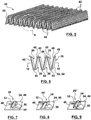
- a heat transfer surface or turbulizer 40 is shown which is similar to turbulizer 14, except that the upper and lower spaced-apart ridges 42, 44 are rounded and the planar fins 46 are inclined with respect to one another. The fins thus would also be inclined with respect to tube walls 28, 30.
- apertures 26 have opposed peripheral edge portions 48, 50.
- Peripheral edge portions 48, 50 have respective flanges 52, 54 that extend transversely from planar fins 24, 46.
- transverse flanges 52, 54 associated with each aperture 26 are angled slightly with respect to one another.
- transverse flanges 52, 54 could be made perpendicular to planar fins 24, 46.
- the flanges are considered to be generally perpendicular to the planar fins 24, 46 for the purposes of this specification.
- all of the apertures 26, or at least the flanges 52, 54 extend in the same direction in the turbulizer.
- flow through these apertures is referred to as being in the high pressure drop direction.
- the pressure drop where the flow is from right to left in Figures 4 and 6 is slightly higher than where the flow is from left to right.
- the flanges 52, 54 on alternating planar fins 24 could extend in opposite directions in the turbulizer. This could also be done in the Figure 6 embodiment if the fins 24 are spaced far enough apart that the flanges 52, 54 would not interfere with one another in adjacent fins.
- Turbulizers 14 and 40 could be located inside tubes 12, so that the flow through the turbulizers is in either direction through apertures 26.
- Figure 10 corresponds to the arrangement of the apertures as indicated in Figures 2 and 5 , where all of the apertures 26 are aligned in the longitudinal direction of heat exchanger tube 12. Apertures 26 are thus aligned in the high pressure drop direction of heat exchanger 10 and some part of the flow through tubes 12 can pass straight through the apertures 26.
- the apertures 26 are slightly offset from the apertures 26 in the next adjacent planar fin 24.
- the apertures 26 are even more offset in respect of the apertures 26 in the next adjacent planar fins 24, and in Figure 13 , apertures 26 are fully offset.
- Figure 14 illustrates that the flanges 52, 54 associated with each aperture 26 could be disposed at different angles relative to planar fins 24. Further, the flanges 52, 54 associated with each aperture 26 could be of different length, width or height. Similarly, the flanges associated with different apertures could also be of different length, width or height. Further, the apertures 26 could be spaced differently, as described further below. The apertures in planar fins 24 could also be located in spaced-apart groups. Figure 15 illustrates that the fin and aperture density could also be varied, if desired, Figure 15 having more fins and apertures than previously described embodiments, and thus having a higher fin and aperture density.
- Figure 16 is similar to Figures 10 to 13 , but it shows that some of the apertures 26' could be wider or larger than apertures 26, and some of the apertures 26" could be narrower or smaller than apertures 26. In Figure 16 , every other fin has these larger and smaller apertures 26' and 26".
- the apertures in alternating fins 24 are of different sizes, and are also spaced apart differently in adjacent planar fins 24.
- Figure 18 shows that the apertures 26, can be spaced apart differently in adjacent or alternating planar fins 24.
- Figure 19 shows that the apertures 26 could be diamond shaped or square in plan view.
- Figure 20 shows that the apertures 26 could be triangular shaped. Preferably the apertures in alternating rows would be inverted (not shown).
- Figure 21 shows that the apertures 26 could be circular in shape. Although two rows of apertures 26 are shown in fins 24, a single row of apertures 26 could be provided as well.
- Figure 22 shows that apertures 26 could be hourglass shaped.
- FIGS 19-22 disclose embodiments that are not part of the claimed invention.
- the method of making heat transfer surfaces or turbulizers 14 and 40 is to first start with a sheet of material, such as aluminum, copper or stainless steel. The sheet of material would then be pierced to form spaced-apart, parallel rows of spaced-apart apertures.
- the apertures could start by making a slit and then expanding the slit to form the peripheral flanges 52, 54. If the material is soft enough, or the apertures are small enough, a continuous peripheral flange could be formed as indicated in Figure 7 . If the material is more brittle or the apertures are larger, an aperture 26" would be formed as indicated in Figure 9 wherein the aperture peripheral flanges split and become discontinuous or jagged during formation.
- Figure 9 shows two different shapes (square and triangular) for the end portions of the peripheral flanges. Normally, it would be one or the other for both end portions, but they could be different, as indicated.
- an H-type slit would be made in the material and the slit opened up or expanded to form the opposed peripheral flange portions 52, 54.
- the apertures 26 are other shapes, such as are shown in Figures 19 to 22 , appropriate piercings would be made, so that when opened up, these shapes would be produced.
- the sheet of material is then bent along lines parallel to the rows of apertures.
- the bend lines would be spaced between the rows of apertures, thereby forming the ridges 20, 22 or 42, 44 along the bend lines and the planar fins 24 extending between the ridges.
- the sheet of material would be bent in opposite transverse directions on alternating bend lines.
- the sheet would be bent along two parallel bend lines between each row of apertures 26, thereby forming the ridges 20, 22 with generally flat peaks.
- the sheet in the Figure 2 embodiment would be bent in the same transverse direction along the parallel bend lines between alternating rows of apertures 26, or this double bend could be produced between only some of the adjacent rows of apertures 26, with the sheet being bent along a single bend line between other adjacent rows of apertures 26, thus producing a combination of the configurations shown in Figures 2 and 5 .
- the slitting of the sheet of material and the formation of the flanged apertures 26 is done in a single operation.
- the sheet can be pierced in the same transverse direction for all the apertures, or the sheet can be pierced in opposite transverse directions in adjacent rows of apertures.
- the sheet of material may be pierced and bent simultaneously, or in separate operations.
- the sheet of material can be pierced to form spaced-apart groups of apertures in each row of apertures. Further, the sheet could be pierced in opposite transverse directions in adjacent groups of apertures in each row of apertures. If the sheet material is soft enough, the sheet material may be stretched while the apertures are being pierced, thereby producing flanges 52, 54 that are elongated or wider or higher than normally would be the case. As indicated above, the apertures 26 are elongate having a longitudinal axis extending in a transverse direction to the ridges 20, 22 and 42, 44.
- the turbulizer could be gathered together after the sheet is bent transversely along the bend lines.
- the planar fins 24 could be angled with respect to one another and with respect to the first and second walls 28, 30 of tubes 12, or they could be substantially perpendicular and parallel.
- the sheet of material could be bent until the planar fins 24 are angled, and then the turbulizer gathered together to make the planar fins parallel to one another.
- both types of heat transfer surfaces 14 and 40 could be used in the same tube 12, and they could be orientated differently, so that some of them are in the high pressure drop direction and some of them are in the low pressure drop direction.
- Flanges 52, 54 could extend in opposite directions in different sections or in different planar fins 24 of the heat transfer surfaces, or portions of same, to vary the pressure drop as desired.
- Multiple sections of a same type of heat transfer surface could be used in each tube 12, again with some of them orientated in the high pressure drop direction and some of them orientated in the low pressure drop direction.
- each tube 12 could be located in each tube 12, again with the type and orientation mixed and matched, as desired.
- the heat transfer surfaces of this invention could be used between the tubes, and they could be used in air-to-air type heat exchangers to increase mixing or turbulence in the fluids flowing through or around the heat exchangers.
- the tubes 12, need not be tubes in the strict sense. They could be formed of mating plate pairs, or a pan and cover construction, or some other structure, as desired.
Landscapes
- Engineering & Computer Science (AREA)
- Physics & Mathematics (AREA)
- Mechanical Engineering (AREA)
- Thermal Sciences (AREA)
- General Engineering & Computer Science (AREA)
- Geometry (AREA)
- Heat-Exchange Devices With Radiators And Conduit Assemblies (AREA)
Claims (24)
- Surface de transfert thermique (14, 40) pour un échangeur thermique (10) comprenant :un élément ondulé comportant des nervures espacées parallèles (20, 22, 42, 44) et des ailettes planes (24, 46) qui s'étendent entre ;les ailettes planes (24, 46) étant formées de manière à comporter des ouvertures espacées (26) qui comportent des parties de bord périphériques opposées (48, 50) ; etlesdites parties de bord périphériques opposées de chaque ouverture (26) incluant des flancs respectifs (52, 54) qui s'étendent vers l'extérieur depuis un unique côté de l'ailette plane (24, 26) en formant ladite ouverture (26) ; et dans laquelle :les ouvertures (26) sont allongées et elles comportent un axe longitudinal qui s'étend dans une direction transversale par rapport aux nervures (20, 22, 42, 44) ; et dans laquelle :la surface de transfert thermique (14, 40) présente une direction de chute de pression faible qui est parallèle aux ailettes planes (24, 46) et une direction de chute de pression élevée qui est transversale par rapport aux ailettes planes (24, 46), les ouvertures (26) étant orientées dans la direction de chute de pression élevée et les flancs (52, 54) s'étendant suivant cette même direction.
- Surface de transfert thermique (14, 40) selon la revendication 1, dans laquelle les flancs (52, 54) associés à chaque ouverture (26) sont angulés l'un par rapport à l'autre.
- Surface de transfert thermique (14, 40) selon la revendication 1, dans laquelle les flancs (52, 54) associés à chaque ouverture sont continus sur la périphérie de l'ouverture (26).
- Surface de transfert thermique (14, 40) selon la revendication 1, dans laquelle les flancs (52, 54) associés à chaque ouverture (26) sont interrompus sur la périphérie de l'ouverture (26).
- Surface de transfert thermique (14, 40) selon la revendication 1, dans laquelle la surface de transfert thermique (14, 40) présente une direction de chute de pression faible qui est parallèle aux ailettes planes (24, 46) et une direction de chute de pression élevée qui est transversale par rapport aux ailettes planes (24, 46), et dans laquelle les ouvertures (26) sont décalées dans la direction de chute de pression élevée.
- Surface de transfert thermique (14, 40) selon la revendication 1, dans laquelle les flancs (52, 54) s'étendent tous dans la même direction dans la surface de transfert thermique (14, 40).
- Surface de transfert thermique (14, 40) selon la revendication 1, dans laquelle les flancs (52, 54) sur des ailettes planes alternées (24, 46) s'étendent dans des directions opposées dans la surface de transfert thermique (14, 40).
- Surface de transfert thermique (14, 40) selon la revendication 1, dans laquelle les ailettes planes (24, 46) sont inclinées les unes par rapport aux autres.
- Surface de transfert thermique (14, 40) selon la revendication 1, dans laquelle les ailettes planes (24, 46) sont parallèles les unes aux autres.
- Surface de transfert thermique (14, 40) selon la revendication 1, dans laquelle au moins certains des flancs (52, 54) sont de façon générale perpendiculaires aux ailettes planes (24, 46).
- Surface de transfert thermique (14, 40) selon la revendication 2, dans laquelle les flancs (52, 54) associés à chaque ouverture (26) sont disposés selon des angles différents par rapport aux ailettes planes (24, 46).
- Surface de transfert thermique (14, 40) selon la revendication 1, dans laquelle les flancs (52, 54) associés à chaque ouverture (26) sont de largeurs différentes.
- Surface de transfert thermique (14, 40) selon la revendication 1, dans laquelle les ouvertures (26) dans chaque ailette plane (24, 46) sont placées selon des groupes espacés.
- Surface de transfert thermique (14, 40) selon la revendication 1, dans laquelle les ouvertures (26) sont de différentes formes.
- Surface de transfert thermique (14, 40) selon la revendication 1, dans laquelle les ouvertures (26) sont de différentes dimensions.
- Surface de transfert thermique (14, 40) selon la revendication 1, dans laquelle les ouvertures (26) sont espacées de façon différente dans des ailettes planes adjacentes (24, 46).
- Echangeur thermique (10) comprenant :un tube de forme générale plate (12) comportant des première et seconde parois espacées (28, 30) ;une surface de transfert thermique ondulée (14, 40) placée dans ledit tube (12), la surface de transfert thermique (14, 40) incluant des nervures espacées parallèles (20, 22, 42, 44), des ailettes planes (24, 46) qui s'étendent entre, des nervures alternées (20, 22, 42, 44) étant respectivement en contact avec les première et seconde parois (28, 30) ;les ailettes planes (24, 46) étant formées de manière à comporter des ouvertures espacées (26) qui comportent des parties de bord périphériques opposées (48 ; 50) ; etlesdites parties de bord périphériques opposées de chaque ouverture (26) incluant des flancs respectifs (52, 54) qui s'étendent vers l'extérieur depuis un unique côté de l'ailette plane (24, 26) en formant ladite ouverture (26) ; dans lequel :le tube (12) comporte un axe longitudinal (34), les nervures (20, 22) de la surface de transfert thermique (14, 40) étant orientées perpendiculairement audit axe longitudinal (34) et le flux au travers du tube (12) étant perpendiculaire auxdites nervures (20, 22) ; et dans lequel :les ouvertures (26) sont allongées et comportent un axe longitudinal qui s'étend dans une direction transversale par rapport aux nervures et par rapport à la direction de flux longitudinale du tube (12).
- Echangeur thermique (10) selon la revendication 17, dans lequel les ailettes planes (24, 46) sont inclinées par rapport aux parois espacées (28, 30).
- Echangeur thermique (10) selon la revendication 17, dans lequel les ailettes planes (24, 46) sont perpendiculaires aux parois espacées (28, 30).
- Echangeur thermique (10) selon la revendication 17, dans lequel le tube (12) comporte des parties d'extrémité respectives (16) qui définissent une entrée de fluide et une sortie de fluide pour l'échangeur thermique.
- Echangeur thermique (10) selon la revendication 18, dans lequel lesdits flancs (52, 54) s'étendent tous de façon générale dans la même direction à l'intérieur du tube (12).
- Echangeur thermique (10) selon la revendication 17, dans lequel les flancs (52, 54) associés à chaque ouverture (26) sont continus sur la périphérie de l'ouverture (26).
- Echangeur thermique (10) selon la revendication 17, dans lequel les flancs (52, 54) associés à chaque ouverture (26) sont interrompus sur la périphérie de l'ouverture (26).
- Echangeur thermique (10) selon la revendication 23, dans lequel les flancs (52, 54) associés à chaque ouverture (26) sont angulés l'un par rapport à l'autre.
Applications Claiming Priority (2)
| Application Number | Priority Date | Filing Date | Title |
|---|---|---|---|
| CA2557422A CA2557422C (fr) | 2006-08-28 | 2006-08-28 | Surfaces de transfert thermique avec ouvertures a collerettes |
| PCT/CA2007/001484 WO2008025131A1 (fr) | 2006-08-28 | 2007-08-23 | Surfaces de transfert de chaleur dotées d'ouvertures à brides |
Publications (3)
| Publication Number | Publication Date |
|---|---|
| EP2064509A1 EP2064509A1 (fr) | 2009-06-03 |
| EP2064509A4 EP2064509A4 (fr) | 2013-06-05 |
| EP2064509B1 true EP2064509B1 (fr) | 2017-01-11 |
Family
ID=39133510
Family Applications (1)
| Application Number | Title | Priority Date | Filing Date |
|---|---|---|---|
| EP07800510.5A Not-in-force EP2064509B1 (fr) | 2006-08-28 | 2007-08-23 | Surfaces de transfert de chaleur dotées d'ouvertures à brides |
Country Status (4)
| Country | Link |
|---|---|
| EP (1) | EP2064509B1 (fr) |
| CN (2) | CN105215228A (fr) |
| CA (1) | CA2557422C (fr) |
| WO (1) | WO2008025131A1 (fr) |
Families Citing this family (3)
| Publication number | Priority date | Publication date | Assignee | Title |
|---|---|---|---|---|
| US20090260789A1 (en) * | 2008-04-21 | 2009-10-22 | Dana Canada Corporation | Heat exchanger with expanded metal turbulizer |
| JP2016080325A (ja) * | 2014-10-22 | 2016-05-16 | カルソニックカンセイ株式会社 | 熱交換器 |
| US11411153B2 (en) * | 2019-07-09 | 2022-08-09 | Dana Canada Corporation | Multi-sided thermal management device for electronic apparatus |
Family Cites Families (9)
| Publication number | Priority date | Publication date | Assignee | Title |
|---|---|---|---|---|
| CA484636A (fr) * | 1952-07-08 | Jensen Arthur | Methode pour former des surfaces a ailettes en epingles de pieces reticulees | |
| JPS649017A (en) * | 1987-05-01 | 1989-01-12 | Texas Instruments Inc | Vehicle and air heater therefor |
| GB8910975D0 (en) * | 1989-05-12 | 1989-06-28 | Imi Radiators | Radiators |
| JPH0492166U (fr) * | 1990-12-04 | 1992-08-11 | ||
| JPH06129734A (ja) * | 1992-10-15 | 1994-05-13 | Showa Alum Corp | 熱交換器 |
| US6378605B1 (en) * | 1999-12-02 | 2002-04-30 | Midwest Research Institute | Heat exchanger with transpired, highly porous fins |
| US6729388B2 (en) * | 2000-01-28 | 2004-05-04 | Behr Gmbh & Co. | Charge air cooler, especially for motor vehicles |
| US20040099408A1 (en) * | 2002-11-26 | 2004-05-27 | Shabtay Yoram Leon | Interconnected microchannel tube |
| JP2006105577A (ja) * | 2004-09-08 | 2006-04-20 | Usui Kokusai Sangyo Kaisha Ltd | フィン構造体および該フィン構造体を内装した伝熱管並びに該伝熱管を組込んだ熱交換器 |
-
2006
- 2006-08-28 CA CA2557422A patent/CA2557422C/fr not_active Expired - Fee Related
-
2007
- 2007-08-23 CN CN201510672799.3A patent/CN105215228A/zh active Pending
- 2007-08-23 WO PCT/CA2007/001484 patent/WO2008025131A1/fr not_active Ceased
- 2007-08-23 EP EP07800510.5A patent/EP2064509B1/fr not_active Not-in-force
- 2007-08-23 CN CNA2007800383399A patent/CN101523151A/zh active Pending
Non-Patent Citations (1)
| Title |
|---|
| None * |
Also Published As
| Publication number | Publication date |
|---|---|
| WO2008025131A1 (fr) | 2008-03-06 |
| EP2064509A4 (fr) | 2013-06-05 |
| CA2557422C (fr) | 2014-10-14 |
| CN101523151A (zh) | 2009-09-02 |
| EP2064509A1 (fr) | 2009-06-03 |
| CA2557422A1 (fr) | 2008-02-28 |
| CN105215228A (zh) | 2016-01-06 |
Similar Documents
| Publication | Publication Date | Title |
|---|---|---|
| US10048020B2 (en) | Heat transfer surfaces with flanged apertures | |
| AU640650B2 (en) | Heat exchangers | |
| US6378605B1 (en) | Heat exchanger with transpired, highly porous fins | |
| US11454448B2 (en) | Enhanced heat transfer surface | |
| CN103119388B (zh) | 板翅式换热器及其制造方法、换热工艺及空气分离工艺 | |
| JP6614140B2 (ja) | 性能強化特徴を備える流体チャネル及びそれを組み込んだデバイス | |
| EP2241851A2 (fr) | Ailette, échangeur thermique et ensemble d'échangeur thermique | |
| US20070012430A1 (en) | Heat exchangers with corrugated heat exchange elements of improved strength | |
| CN101194137B (zh) | 具有在通路中形成多个通道的热交换结构的板式换热器 | |
| US7059397B2 (en) | Heat exchanger with brazed plates | |
| US20090260789A1 (en) | Heat exchanger with expanded metal turbulizer | |
| EP3330657B1 (fr) | Lamelle d'évacuation de l'air d'un échangeur de chaleur et son procédé de fabrication | |
| CN111712683A (zh) | 间接热交换器 | |
| EP2064509B1 (fr) | Surfaces de transfert de chaleur dotées d'ouvertures à brides | |
| EP0838650B1 (fr) | Echangeur de chaleur avec plaques d'ailettes bosselées | |
| CA2330084C (fr) | Echangeur de chaleur avec ailettes tres poreuses fonctionnant par transpiration | |
| RU10861U1 (ru) | Пакет пластин для теплообменника | |
| EP0097612A2 (fr) | Echangeur de chaleur | |
| WO2007009220A1 (fr) | Echangeurs thermiques pourvus d'elements d'echange thermique ondules presentant une resistance amelioree | |
| JP2000105089A (ja) | 熱交換器 | |
| JPH05223406A (ja) | 熱交換器 |
Legal Events
| Date | Code | Title | Description |
|---|---|---|---|
| PUAI | Public reference made under article 153(3) epc to a published international application that has entered the european phase |
Free format text: ORIGINAL CODE: 0009012 |
|
| 17P | Request for examination filed |
Effective date: 20090327 |
|
| AK | Designated contracting states |
Kind code of ref document: A1 Designated state(s): AT BE BG CH CY CZ DE DK EE ES FI FR GB GR HU IE IS IT LI LT LU LV MC MT NL PL PT RO SE SI SK TR |
|
| AX | Request for extension of the european patent |
Extension state: AL BA HR MK RS |
|
| DAX | Request for extension of the european patent (deleted) | ||
| A4 | Supplementary search report drawn up and despatched |
Effective date: 20130508 |
|
| RIC1 | Information provided on ipc code assigned before grant |
Ipc: B21D 53/04 20060101ALI20130502BHEP Ipc: B21D 21/00 20060101ALI20130502BHEP Ipc: F28F 1/04 20060101ALI20130502BHEP Ipc: F28F 13/06 20060101AFI20130502BHEP Ipc: B21D 13/10 20060101ALI20130502BHEP Ipc: F28F 13/12 20060101ALI20130502BHEP Ipc: B23P 15/26 20060101ALI20130502BHEP Ipc: F28F 1/40 20060101ALI20130502BHEP |
|
| GRAP | Despatch of communication of intention to grant a patent |
Free format text: ORIGINAL CODE: EPIDOSNIGR1 |
|
| INTG | Intention to grant announced |
Effective date: 20160810 |
|
| GRAS | Grant fee paid |
Free format text: ORIGINAL CODE: EPIDOSNIGR3 |
|
| GRAA | (expected) grant |
Free format text: ORIGINAL CODE: 0009210 |
|
| AK | Designated contracting states |
Kind code of ref document: B1 Designated state(s): AT BE BG CH CY CZ DE DK EE ES FI FR GB GR HU IE IS IT LI LT LU LV MC MT NL PL PT RO SE SI SK TR |
|
| REG | Reference to a national code |
Ref country code: GB Ref legal event code: FG4D |
|
| REG | Reference to a national code |
Ref country code: CH Ref legal event code: EP |
|
| REG | Reference to a national code |
Ref country code: AT Ref legal event code: REF Ref document number: 861693 Country of ref document: AT Kind code of ref document: T Effective date: 20170115 |
|
| REG | Reference to a national code |
Ref country code: IE Ref legal event code: FG4D |
|
| REG | Reference to a national code |
Ref country code: DE Ref legal event code: R096 Ref document number: 602007049509 Country of ref document: DE |
|
| REG | Reference to a national code |
Ref country code: LT Ref legal event code: MG4D |
|
| REG | Reference to a national code |
Ref country code: NL Ref legal event code: MP Effective date: 20170111 |
|
| REG | Reference to a national code |
Ref country code: AT Ref legal event code: MK05 Ref document number: 861693 Country of ref document: AT Kind code of ref document: T Effective date: 20170111 |
|
| PG25 | Lapsed in a contracting state [announced via postgrant information from national office to epo] |
Ref country code: NL Free format text: LAPSE BECAUSE OF FAILURE TO SUBMIT A TRANSLATION OF THE DESCRIPTION OR TO PAY THE FEE WITHIN THE PRESCRIBED TIME-LIMIT Effective date: 20170111 |
|
| PG25 | Lapsed in a contracting state [announced via postgrant information from national office to epo] |
Ref country code: FI Free format text: LAPSE BECAUSE OF FAILURE TO SUBMIT A TRANSLATION OF THE DESCRIPTION OR TO PAY THE FEE WITHIN THE PRESCRIBED TIME-LIMIT Effective date: 20170111 Ref country code: LT Free format text: LAPSE BECAUSE OF FAILURE TO SUBMIT A TRANSLATION OF THE DESCRIPTION OR TO PAY THE FEE WITHIN THE PRESCRIBED TIME-LIMIT Effective date: 20170111 Ref country code: GR Free format text: LAPSE BECAUSE OF FAILURE TO SUBMIT A TRANSLATION OF THE DESCRIPTION OR TO PAY THE FEE WITHIN THE PRESCRIBED TIME-LIMIT Effective date: 20170412 Ref country code: IS Free format text: LAPSE BECAUSE OF FAILURE TO SUBMIT A TRANSLATION OF THE DESCRIPTION OR TO PAY THE FEE WITHIN THE PRESCRIBED TIME-LIMIT Effective date: 20170511 |
|
| PG25 | Lapsed in a contracting state [announced via postgrant information from national office to epo] |
Ref country code: SE Free format text: LAPSE BECAUSE OF FAILURE TO SUBMIT A TRANSLATION OF THE DESCRIPTION OR TO PAY THE FEE WITHIN THE PRESCRIBED TIME-LIMIT Effective date: 20170111 Ref country code: LV Free format text: LAPSE BECAUSE OF FAILURE TO SUBMIT A TRANSLATION OF THE DESCRIPTION OR TO PAY THE FEE WITHIN THE PRESCRIBED TIME-LIMIT Effective date: 20170111 Ref country code: PT Free format text: LAPSE BECAUSE OF FAILURE TO SUBMIT A TRANSLATION OF THE DESCRIPTION OR TO PAY THE FEE WITHIN THE PRESCRIBED TIME-LIMIT Effective date: 20170511 Ref country code: ES Free format text: LAPSE BECAUSE OF FAILURE TO SUBMIT A TRANSLATION OF THE DESCRIPTION OR TO PAY THE FEE WITHIN THE PRESCRIBED TIME-LIMIT Effective date: 20170111 Ref country code: BG Free format text: LAPSE BECAUSE OF FAILURE TO SUBMIT A TRANSLATION OF THE DESCRIPTION OR TO PAY THE FEE WITHIN THE PRESCRIBED TIME-LIMIT Effective date: 20170411 Ref country code: PL Free format text: LAPSE BECAUSE OF FAILURE TO SUBMIT A TRANSLATION OF THE DESCRIPTION OR TO PAY THE FEE WITHIN THE PRESCRIBED TIME-LIMIT Effective date: 20170111 Ref country code: AT Free format text: LAPSE BECAUSE OF FAILURE TO SUBMIT A TRANSLATION OF THE DESCRIPTION OR TO PAY THE FEE WITHIN THE PRESCRIBED TIME-LIMIT Effective date: 20170111 |
|
| REG | Reference to a national code |
Ref country code: DE Ref legal event code: R097 Ref document number: 602007049509 Country of ref document: DE |
|
| PG25 | Lapsed in a contracting state [announced via postgrant information from national office to epo] |
Ref country code: SK Free format text: LAPSE BECAUSE OF FAILURE TO SUBMIT A TRANSLATION OF THE DESCRIPTION OR TO PAY THE FEE WITHIN THE PRESCRIBED TIME-LIMIT Effective date: 20170111 Ref country code: CZ Free format text: LAPSE BECAUSE OF FAILURE TO SUBMIT A TRANSLATION OF THE DESCRIPTION OR TO PAY THE FEE WITHIN THE PRESCRIBED TIME-LIMIT Effective date: 20170111 Ref country code: EE Free format text: LAPSE BECAUSE OF FAILURE TO SUBMIT A TRANSLATION OF THE DESCRIPTION OR TO PAY THE FEE WITHIN THE PRESCRIBED TIME-LIMIT Effective date: 20170111 Ref country code: RO Free format text: LAPSE BECAUSE OF FAILURE TO SUBMIT A TRANSLATION OF THE DESCRIPTION OR TO PAY THE FEE WITHIN THE PRESCRIBED TIME-LIMIT Effective date: 20170111 Ref country code: IT Free format text: LAPSE BECAUSE OF FAILURE TO SUBMIT A TRANSLATION OF THE DESCRIPTION OR TO PAY THE FEE WITHIN THE PRESCRIBED TIME-LIMIT Effective date: 20170111 |
|
| PLBE | No opposition filed within time limit |
Free format text: ORIGINAL CODE: 0009261 |
|
| STAA | Information on the status of an ep patent application or granted ep patent |
Free format text: STATUS: NO OPPOSITION FILED WITHIN TIME LIMIT |
|
| PG25 | Lapsed in a contracting state [announced via postgrant information from national office to epo] |
Ref country code: DK Free format text: LAPSE BECAUSE OF FAILURE TO SUBMIT A TRANSLATION OF THE DESCRIPTION OR TO PAY THE FEE WITHIN THE PRESCRIBED TIME-LIMIT Effective date: 20170111 |
|
| 26N | No opposition filed |
Effective date: 20171012 |
|
| PG25 | Lapsed in a contracting state [announced via postgrant information from national office to epo] |
Ref country code: SI Free format text: LAPSE BECAUSE OF FAILURE TO SUBMIT A TRANSLATION OF THE DESCRIPTION OR TO PAY THE FEE WITHIN THE PRESCRIBED TIME-LIMIT Effective date: 20170111 |
|
| REG | Reference to a national code |
Ref country code: CH Ref legal event code: PL |
|
| PG25 | Lapsed in a contracting state [announced via postgrant information from national office to epo] |
Ref country code: MC Free format text: LAPSE BECAUSE OF FAILURE TO SUBMIT A TRANSLATION OF THE DESCRIPTION OR TO PAY THE FEE WITHIN THE PRESCRIBED TIME-LIMIT Effective date: 20170111 |
|
| GBPC | Gb: european patent ceased through non-payment of renewal fee |
Effective date: 20170823 |
|
| PG25 | Lapsed in a contracting state [announced via postgrant information from national office to epo] |
Ref country code: LI Free format text: LAPSE BECAUSE OF NON-PAYMENT OF DUE FEES Effective date: 20170831 Ref country code: CH Free format text: LAPSE BECAUSE OF NON-PAYMENT OF DUE FEES Effective date: 20170831 |
|
| REG | Reference to a national code |
Ref country code: FR Ref legal event code: ST Effective date: 20180430 |
|
| REG | Reference to a national code |
Ref country code: IE Ref legal event code: MM4A |
|
| REG | Reference to a national code |
Ref country code: BE Ref legal event code: MM Effective date: 20170831 |
|
| PG25 | Lapsed in a contracting state [announced via postgrant information from national office to epo] |
Ref country code: LU Free format text: LAPSE BECAUSE OF NON-PAYMENT OF DUE FEES Effective date: 20170823 |
|
| PG25 | Lapsed in a contracting state [announced via postgrant information from national office to epo] |
Ref country code: IE Free format text: LAPSE BECAUSE OF NON-PAYMENT OF DUE FEES Effective date: 20170823 Ref country code: GB Free format text: LAPSE BECAUSE OF NON-PAYMENT OF DUE FEES Effective date: 20170823 |
|
| PG25 | Lapsed in a contracting state [announced via postgrant information from national office to epo] |
Ref country code: FR Free format text: LAPSE BECAUSE OF NON-PAYMENT OF DUE FEES Effective date: 20170831 Ref country code: BE Free format text: LAPSE BECAUSE OF NON-PAYMENT OF DUE FEES Effective date: 20170831 |
|
| PG25 | Lapsed in a contracting state [announced via postgrant information from national office to epo] |
Ref country code: MT Free format text: LAPSE BECAUSE OF NON-PAYMENT OF DUE FEES Effective date: 20170823 |
|
| PG25 | Lapsed in a contracting state [announced via postgrant information from national office to epo] |
Ref country code: HU Free format text: LAPSE BECAUSE OF FAILURE TO SUBMIT A TRANSLATION OF THE DESCRIPTION OR TO PAY THE FEE WITHIN THE PRESCRIBED TIME-LIMIT; INVALID AB INITIO Effective date: 20070823 |
|
| PG25 | Lapsed in a contracting state [announced via postgrant information from national office to epo] |
Ref country code: CY Free format text: LAPSE BECAUSE OF NON-PAYMENT OF DUE FEES Effective date: 20170111 |
|
| PGFP | Annual fee paid to national office [announced via postgrant information from national office to epo] |
Ref country code: DE Payment date: 20190828 Year of fee payment: 13 |
|
| PG25 | Lapsed in a contracting state [announced via postgrant information from national office to epo] |
Ref country code: TR Free format text: LAPSE BECAUSE OF FAILURE TO SUBMIT A TRANSLATION OF THE DESCRIPTION OR TO PAY THE FEE WITHIN THE PRESCRIBED TIME-LIMIT Effective date: 20170111 |
|
| REG | Reference to a national code |
Ref country code: DE Ref legal event code: R119 Ref document number: 602007049509 Country of ref document: DE |
|
| PG25 | Lapsed in a contracting state [announced via postgrant information from national office to epo] |
Ref country code: DE Free format text: LAPSE BECAUSE OF NON-PAYMENT OF DUE FEES Effective date: 20210302 |