EP0106731A1 - Einrichtung zum Transport von Schnee - Google Patents
Einrichtung zum Transport von Schnee Download PDFInfo
- Publication number
- EP0106731A1 EP0106731A1 EP83401794A EP83401794A EP0106731A1 EP 0106731 A1 EP0106731 A1 EP 0106731A1 EP 83401794 A EP83401794 A EP 83401794A EP 83401794 A EP83401794 A EP 83401794A EP 0106731 A1 EP0106731 A1 EP 0106731A1
- Authority
- EP
- European Patent Office
- Prior art keywords
- air
- snow
- pipe
- mixture
- air generator
- Prior art date
- Legal status (The legal status is an assumption and is not a legal conclusion. Google has not performed a legal analysis and makes no representation as to the accuracy of the status listed.)
- Granted
Links
- 238000009434 installation Methods 0.000 claims abstract description 31
- 239000000203 mixture Substances 0.000 claims abstract description 29
- 238000004519 manufacturing process Methods 0.000 claims abstract description 23
- 238000005070 sampling Methods 0.000 claims description 8
- 210000000056 organ Anatomy 0.000 claims description 5
- 230000032258 transport Effects 0.000 description 22
- 235000016623 Fragaria vesca Nutrition 0.000 description 1
- 240000009088 Fragaria x ananassa Species 0.000 description 1
- 235000011363 Fragaria x ananassa Nutrition 0.000 description 1
- 238000004873 anchoring Methods 0.000 description 1
- 230000015572 biosynthetic process Effects 0.000 description 1
- 238000006073 displacement reaction Methods 0.000 description 1
- 239000000463 material Substances 0.000 description 1
- 230000008018 melting Effects 0.000 description 1
- 238000002844 melting Methods 0.000 description 1
- 238000011144 upstream manufacturing Methods 0.000 description 1
Images
Classifications
-
- E—FIXED CONSTRUCTIONS
- E01—CONSTRUCTION OF ROADS, RAILWAYS, OR BRIDGES
- E01H—STREET CLEANING; CLEANING OF PERMANENT WAYS; CLEANING BEACHES; DISPERSING OR PREVENTING FOG IN GENERAL CLEANING STREET OR RAILWAY FURNITURE OR TUNNEL WALLS
- E01H4/00—Working on surfaces of snow or ice in order to make them suitable for traffic or sporting purposes, e.g. by compacting snow
- E01H4/02—Working on surfaces of snow or ice in order to make them suitable for traffic or sporting purposes, e.g. by compacting snow for sporting purposes, e.g. preparation of ski trails; Construction of artificial surfacings for snow or ice sports ; Trails specially adapted for on-the-snow vehicles, e.g. devices adapted for ski-trails
-
- F—MECHANICAL ENGINEERING; LIGHTING; HEATING; WEAPONS; BLASTING
- F25—REFRIGERATION OR COOLING; COMBINED HEATING AND REFRIGERATION SYSTEMS; HEAT PUMP SYSTEMS; MANUFACTURE OR STORAGE OF ICE; LIQUEFACTION SOLIDIFICATION OF GASES
- F25C—PRODUCING, WORKING OR HANDLING ICE
- F25C3/00—Processes or apparatus specially adapted for producing ice or snow for winter sports or similar recreational purposes, e.g. for sporting installations; Producing artificial snow
- F25C3/04—Processes or apparatus specially adapted for producing ice or snow for winter sports or similar recreational purposes, e.g. for sporting installations; Producing artificial snow for sledging or ski trails; Producing artificial snow
-
- F—MECHANICAL ENGINEERING; LIGHTING; HEATING; WEAPONS; BLASTING
- F25—REFRIGERATION OR COOLING; COMBINED HEATING AND REFRIGERATION SYSTEMS; HEAT PUMP SYSTEMS; MANUFACTURE OR STORAGE OF ICE; LIQUEFACTION SOLIDIFICATION OF GASES
- F25C—PRODUCING, WORKING OR HANDLING ICE
- F25C2303/00—Special arrangements or features for producing ice or snow for winter sports or similar recreational purposes, e.g. for sporting installations; Special arrangements or features for producing artificial snow
- F25C2303/044—Snow making using additional features, e.g. additives, liquid gas
Definitions
- the present invention relates to a snow transfer installation.
- a snow removal operation consisting in evacuating snow from the locations where it constitutes a nuisance towards a place of discharge which can be either a ski slope (it is therefore possible to carry out a snowmaking operation in parallel ) or a discharge.
- the fixed installation can only be used in places where there are snow piles.
- the mobile installation has several faults, mainly excessive weight requiring the use of oversized carrier vehicles. Snow removal operations near homes using such a mobile installation have a high noise level, particularly annoying when these operations are carried out at night.
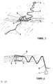
- An object of the present invention consists of a snow transfer installation comprising at least one member for removing snow associated with a member for producing a mixture of snow and air, said members for removing and producing mixture being mounted on a vehicle, a pipe for transporting the snow and air mixture, an air generator, characterized in that the air generator is independent of the mixture sampling and production organs and is connected to the member for producing a mixture by means of a pipe of which at least a portion is flexible.
- the air generator is not mounted on the vehicle carrying the snow removal member and the member for producing a mixture of air and snow; it is independent of said vehicle and can be located at a chosen location, for the duration of the operations, without having to permanently accompany the assembly constituted by the removal member and the production member.
- the air generator can constitute a fixed station, permanently located without having to be moved. It can thus be installed on the edge of a ski slope, a path, a road or in a room. It includes a fan and an energy source (autonomous thermal engine or electric motor) delivering its power to the fan.
- the air generator can also constitute a mobile station independently of the vehicle carrying the sampling and production organs; the engine is then of the thermal type.
- This mobile station can be carried on the platform of a caterpillar or a road vehicle or simply carried by a sledge which will be towed by means of an annexed machine for installation.
- the mobile station comprising the air generator is generally stationary.
- the air generator is connected to the member for producing the snow and air mixture by means of a pipe of which at least a portion is flexible.
- the entire pipe is flexible so as to allow the vehicle carrying the sampling and production members to move relative to the air generator, stationary, over the greatest possible distance and compatible with correct operation of the installation. .
- a pipe length of around 50 meters already allows the installation to have remarkable productivity. Of course, all measures will be taken to avoid the line being crushed by the carrier vehicle.
- the pipe can for example be coiled behind said vehicle.
- the snow removal member is, for example, a cutter of the type described in French patent No. 2,289,414.
- the member for producing the air and snow mixture is for example an injector (rotary lock) as described in the same patent.
- the cutter is driven either by a hydraulic motor itself driven by a pump integral with the carrier vehicle, or by a mechanical PTO as found on agricultural motorcycle tractors.
- the injector is for example driven by a hydraulic motor, the pump of which can be driven by any power take-off.
- sampling and production organs are associated on a carrier vehicle such as a caterpillar or a motorcycle tractor.
- Snow, collected by the strawberry, is admitted into the injector in which air from the air generator is also admitted by means of the pipe provided for this purpose.
- the mixture of snow and air thus produced is admitted into a pipe which it traverses and at the end of which the snow is discharged either towards a discharge or towards a ski slope to be snowed (in the latter case the end of the pipe is advantageously equipped with an ejection nozzle).
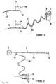
- two pipes are connected to the production member carried by the vehicle: the air pipe coming from the air generator and the pipe for transporting the snow and air mixture.
- the air line generally has a smaller diameter than that of the transport line.
- This transport pipe is advantageously flexible over at least a fraction of its length.
- the length of the transport pipe is arbitrary and is essentially a function of the distance which separates the carrier vehicle from the place where the snow is to be removed.
- a particular arrangement of the installation consists in using a set of pipes having the same length and an air-generating station with which the end of another portion of transport pipe is associated. It is then noted that a carrier vehicle can thus be connected by means of an air duct which is integral with it to an air generator and by means of a transport duct which is also integral with it at the end of the other portion of the transport pipe associated with said air generator.
- the two lines integral with the vehicle are secured to each other.
- a carrier vehicle can then snow-clear snow-covered locations located near an air generator, for example a stationary one, then go with its set of air-transport pipes to another generator near which it will operate after the pipe connections air to the generator on the one hand, and its transport line to the other portion of the transport line associated with the air generator, on the other hand, will have been made.
- This particular arrangement allows great autonomy, avoids displacement and carrying by the vehicle carrying very long driving lengths and makes the use of the installation very flexible.
- the installation can be such that the pipe connecting the air generator to the production member is partially fixed to the ground, for example anchored by any known means in the deep layers of snow.
- the part fixed to the ground of the air duct can be made of a rigid material. According to this particular mode, it is then possible to supply air to a production member located at a significant distance from the air generator, without having to handle long lengths of pipe.
- the transport pipe can also be fixed to the ground and be partially rigid.
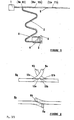
- a pipe fixed to the ground can, by means of the arrangements described below, convey air over part of its length and a mixture of snow and air over the other part of its length.
- This particular operation is possible by providing said rigid pipe with sockets making it possible to connect on the one hand a flexible air pipe and on the other hand a flexible transport pipe, the other ends of which are connected, respectively, to the upstream and downstream of the production unit.
- This rigid pipe can be fitted with valves, and the various sockets are fitted with shutters when they are not operating.
- outlets are provided with folding flaps allowing or not injecting the compressed air and collecting the snow and air mixture by means of said outlets.
- said sockets are coupled and mounted in pairs on the rigid pipe.
- said folding flaps are automatically controlled. This means that when a pipe is not connected to an outlet, the shutter is in the closed position and does not, in particular, allow air to escape from the pipe.
- means provided on said socket cause the flap to fold down and allow the air to engage in the flexible pipe, or to the mixture of snow and air coming from the flexible pipe connected downstream of the production member to propagate in the fixed pipe.
- the installation according to the invention is much more manageable than known installations. More particularly, it makes it possible to use high power air generators without increasing the load on the carrier vehicles, thus limited to the low weight of all of the sampling and mixture production members.
- the distance traveled by the air alone in the pipe which rests on the snow makes it possible to cool it and thus to avoid a partial melting of "cold" snow, the risk of which is the formation of a film of ice on the inner wall of the pipe on the first tens of meters of transport.
- the installation according to the invention finds a particularly important application in the snow removal of places, parking areas, outdoor skating rinks, paths etc ...
- the device according to FIG. 5 is particularly advantageous for snow removal from surfaces such as large parking areas.
- the main pipe (8) is then arranged along a long side of the parking area, one of its ends being connected to the air generator (1) located in a room, the other end being located in a landfill.
- the ends of the flexible pipes (2) and (6) coming from the vehicle (4) are then connected, respectively and successively to the pairs of sockets (9a-9b), (10a-10b), (11a-11b), etc. to carry out snow removal in portions of the surface of the parking area in question. It is advantageous in this case to install the main pipe (8) not on the ground but on posts to make it aerial.
Landscapes
- Engineering & Computer Science (AREA)
- Physics & Mathematics (AREA)
- Mechanical Engineering (AREA)
- Thermal Sciences (AREA)
- General Engineering & Computer Science (AREA)
- Architecture (AREA)
- Civil Engineering (AREA)
- Structural Engineering (AREA)
- Cleaning Of Streets, Tracks, Or Beaches (AREA)
- Centrifugal Separators (AREA)
- Air Transport Of Granular Materials (AREA)
- Buildings Adapted To Withstand Abnormal External Influences (AREA)
Priority Applications (1)
| Application Number | Priority Date | Filing Date | Title |
|---|---|---|---|
| AT83401794T ATE20828T1 (de) | 1982-09-17 | 1983-09-14 | Einrichtung zum transport von schnee. |
Applications Claiming Priority (2)
| Application Number | Priority Date | Filing Date | Title |
|---|---|---|---|
| FR8215687A FR2533244B1 (fr) | 1982-09-17 | 1982-09-17 | Installation de transfert de neige |
| FR8215687 | 1982-09-17 |
Publications (2)
| Publication Number | Publication Date |
|---|---|
| EP0106731A1 true EP0106731A1 (de) | 1984-04-25 |
| EP0106731B1 EP0106731B1 (de) | 1986-07-23 |
Family
ID=9277518
Family Applications (1)
| Application Number | Title | Priority Date | Filing Date |
|---|---|---|---|
| EP83401794A Expired EP0106731B1 (de) | 1982-09-17 | 1983-09-14 | Einrichtung zum Transport von Schnee |
Country Status (6)
| Country | Link |
|---|---|
| US (1) | US4538369A (de) |
| EP (1) | EP0106731B1 (de) |
| AT (1) | ATE20828T1 (de) |
| CA (1) | CA1234168A (de) |
| DE (1) | DE3364725D1 (de) |
| FR (1) | FR2533244B1 (de) |
Cited By (1)
| Publication number | Priority date | Publication date | Assignee | Title |
|---|---|---|---|---|
| FR2597131A1 (fr) * | 1986-04-15 | 1987-10-16 | Tech Realisations Et | Procede et dispositif de transport pneumatique de la neige |
Families Citing this family (5)
| Publication number | Priority date | Publication date | Assignee | Title |
|---|---|---|---|---|
| FR2607909B1 (fr) * | 1986-12-05 | 1992-01-17 | York Froid Ind | Procede d'enneigement de pistes artificielles de ski alpin ou nordique et moyens de mise en oeuvre du procede |
| US7290722B1 (en) | 2003-12-16 | 2007-11-06 | Snow Machines, Inc. | Method and apparatus for making snow |
| US20100202834A1 (en) * | 2007-01-18 | 2010-08-12 | Joseph Leitner | Snow transportation system |
| DK3042996T3 (en) * | 2015-01-12 | 2017-10-23 | Boschung Marcel Ag | Snow removal vehicle with a sweeping fan |
| EP3455566B1 (de) * | 2016-03-07 | 2021-08-18 | Industries SnöFlake Inc. | Fördervorrichtung für eine beschneiungsanlage |
Citations (5)
| Publication number | Priority date | Publication date | Assignee | Title |
|---|---|---|---|---|
| US2676471A (en) * | 1950-12-14 | 1954-04-27 | Tey Mfg Corp | Method for making and distributing snow |
| US3257815A (en) * | 1964-07-10 | 1966-06-28 | Conch Int Methane Ltd | Method and apparatus for the largescale production of snow fields for sports use |
| US3706414A (en) * | 1970-10-07 | 1972-12-19 | Herman K Dupre | Apparatus for making snow |
| FR2289414A1 (fr) * | 1974-10-30 | 1976-05-28 | Tech Realisations Et | Procede et dispositif de manutention de neige |
| FR2327172A2 (fr) * | 1975-10-10 | 1977-05-06 | Tech Realisations Et | Procede et dispositif de manutention de neige |
Family Cites Families (4)
| Publication number | Priority date | Publication date | Assignee | Title |
|---|---|---|---|---|
| US1468977A (en) * | 1922-11-28 | 1923-09-25 | Schiesari Mario | Method of and apparatus for removing snow |
| DE2548338C3 (de) * | 1974-10-30 | 1979-09-13 | Etudes Techniques Et Realisations (E.T.R.), Douai, Nord (Frankreich) | Verfahren zur Aufnahme von Schnee und gezielten Verteilung desselben auf einer Skipiste sowie Vorrichtung zur Durchführung des Verfahrens |
| US4249322A (en) * | 1979-06-21 | 1981-02-10 | Mclaughlin Charles S | Snowplow |
| US4404762A (en) * | 1982-02-08 | 1983-09-20 | Munsterer Gerald A | Ski trail resurfacing apparatus |
-
1982
- 1982-09-17 FR FR8215687A patent/FR2533244B1/fr not_active Expired
-
1983
- 1983-09-14 EP EP83401794A patent/EP0106731B1/de not_active Expired
- 1983-09-14 AT AT83401794T patent/ATE20828T1/de not_active IP Right Cessation
- 1983-09-14 DE DE8383401794T patent/DE3364725D1/de not_active Expired
- 1983-09-16 CA CA000436830A patent/CA1234168A/fr not_active Expired
- 1983-09-19 US US06/533,592 patent/US4538369A/en not_active Expired - Fee Related
Patent Citations (5)
| Publication number | Priority date | Publication date | Assignee | Title |
|---|---|---|---|---|
| US2676471A (en) * | 1950-12-14 | 1954-04-27 | Tey Mfg Corp | Method for making and distributing snow |
| US3257815A (en) * | 1964-07-10 | 1966-06-28 | Conch Int Methane Ltd | Method and apparatus for the largescale production of snow fields for sports use |
| US3706414A (en) * | 1970-10-07 | 1972-12-19 | Herman K Dupre | Apparatus for making snow |
| FR2289414A1 (fr) * | 1974-10-30 | 1976-05-28 | Tech Realisations Et | Procede et dispositif de manutention de neige |
| FR2327172A2 (fr) * | 1975-10-10 | 1977-05-06 | Tech Realisations Et | Procede et dispositif de manutention de neige |
Cited By (2)
| Publication number | Priority date | Publication date | Assignee | Title |
|---|---|---|---|---|
| FR2597131A1 (fr) * | 1986-04-15 | 1987-10-16 | Tech Realisations Et | Procede et dispositif de transport pneumatique de la neige |
| EP0242279A1 (de) * | 1986-04-15 | 1987-10-21 | ETUDES TECHNIQUES ET REALISATIONS S.A. CdF Ingénierie | Verfahren und Vorrichtung zum pneumatischen Schnee-Transport |
Also Published As
| Publication number | Publication date |
|---|---|
| EP0106731B1 (de) | 1986-07-23 |
| FR2533244B1 (fr) | 1985-02-15 |
| ATE20828T1 (de) | 1986-08-15 |
| FR2533244A1 (fr) | 1984-03-23 |
| DE3364725D1 (en) | 1986-08-28 |
| US4538369A (en) | 1985-09-03 |
| CA1234168A (fr) | 1988-03-15 |
Similar Documents
| Publication | Publication Date | Title |
|---|---|---|
| EP2908918B1 (de) | Kompaktantriebseinheit mit nebeneinanderliegenden bahnen | |
| EP0106731B1 (de) | Einrichtung zum Transport von Schnee | |
| CA2700581A1 (fr) | Dispositif de guidage et de captage d'energie electrique au sol pour vehicule, et vehicule de transport urbain equipe d'un tel dispositif | |
| EP0540406A1 (de) | Schutzsystem eines Getriebes, insbesondere eines Hubschraubergetriebes, im Falle eines Schmierölverlustes | |
| WO1995018895A1 (fr) | Dispositif de comblement d'une tranchee creusee dans le fond sous-marin pour recouvrir une canalisation deposee dans ladite tranchee | |
| WO2005054667A2 (fr) | Turbine et centrale hydraulique pour tres basse chute | |
| EP3207793A1 (de) | Maschine zum reinigen von boxen und entfernen von mist | |
| FR2679104A1 (fr) | Dispositif permettant d'assurer le prelevement et le stockage d'herbe ou produits similaires monte sur un vehicule. | |
| WO2023083639A1 (fr) | Module de refroidissement pour véhicule automobile avec un système de drainage | |
| CA2474081A1 (fr) | Procede d'installation d'un cable de fortes ou moyennes puissances dans le sol | |
| FR3024939A1 (fr) | Machine a curer les box et enlever le fumier | |
| EP0453358B1 (de) | Vorrichtung zum Sammeln und Abführen von Gärungsgasen, insbesondere aus dem in Schichten in einer Müllgrube deponierten und verfestigten Hausmüll | |
| FR2843602A1 (fr) | Accouplement rapide pour accoupler un outil a la fleche d' une pelle excavatrice hydraulique | |
| FR2982229A1 (fr) | Systeme de transfert de sable pour l'alimentation d'une sabliere de locomotive | |
| FR2541200A1 (fr) | Dispositif pour l'obturation d'un orifice de passage d'air, en particulier d'air de balayage d'un radiateur dans un circuit de refroidissement de moteur | |
| EP1781887A1 (de) | Verfahren zum befestigen und installieren eines tors und installationsbereites tor | |
| FR3103030A1 (fr) | Dispositif de pulvérisation pour la fabrication de neige artificielle et son procédé de mise en œuvre | |
| FR3028815A1 (fr) | Remorque pour la mise a l'eau et la manutention d'embarcations legeres | |
| FR2871959A1 (fr) | Poste de transformation electrique a aire de manoeuvre interieure. | |
| FR3144174A1 (fr) | Barrage mobile | |
| EP0823370B1 (de) | Antriebsvorrichtung für einen Verriegelungszylinder eines Fahrwerkslenkers eines Fahrzeuges | |
| FR2957576A1 (fr) | Agencement pour la liaison amovible d'une batterie d'alimentation d'un moteur d'entrainement d'un vehicule automobile | |
| FR2531118A1 (fr) | Element de barrage hydraulique et procedes pour son installation | |
| FR2652103A1 (fr) | Dispositif multifonctionnel de deneigement des surfaces et voies de circulation, destine a equiper une base mobile de vehicule. | |
| WO2002019817A1 (fr) | Dispositif de desherbage thermique |
Legal Events
| Date | Code | Title | Description |
|---|---|---|---|
| PUAI | Public reference made under article 153(3) epc to a published international application that has entered the european phase |
Free format text: ORIGINAL CODE: 0009012 |
|
| AK | Designated contracting states |
Designated state(s): AT CH DE FR IT LI |
|
| 17P | Request for examination filed |
Effective date: 19840514 |
|
| ITF | It: translation for a ep patent filed | ||
| GRAA | (expected) grant |
Free format text: ORIGINAL CODE: 0009210 |
|
| AK | Designated contracting states |
Kind code of ref document: B1 Designated state(s): AT CH DE FR IT LI |
|
| REF | Corresponds to: |
Ref document number: 20828 Country of ref document: AT Date of ref document: 19860815 Kind code of ref document: T |
|
| REF | Corresponds to: |
Ref document number: 3364725 Country of ref document: DE Date of ref document: 19860828 |
|
| PLBE | No opposition filed within time limit |
Free format text: ORIGINAL CODE: 0009261 |
|
| STAA | Information on the status of an ep patent application or granted ep patent |
Free format text: STATUS: NO OPPOSITION FILED WITHIN TIME LIMIT |
|
| 26N | No opposition filed | ||
| PGFP | Annual fee paid to national office [announced via postgrant information from national office to epo] |
Ref country code: FR Payment date: 19890726 Year of fee payment: 7 |
|
| PGFP | Annual fee paid to national office [announced via postgrant information from national office to epo] |
Ref country code: AT Payment date: 19890913 Year of fee payment: 7 |
|
| PGFP | Annual fee paid to national office [announced via postgrant information from national office to epo] |
Ref country code: CH Payment date: 19890927 Year of fee payment: 7 |
|
| ITTA | It: last paid annual fee | ||
| PG25 | Lapsed in a contracting state [announced via postgrant information from national office to epo] |
Ref country code: AT Effective date: 19900914 |
|
| PG25 | Lapsed in a contracting state [announced via postgrant information from national office to epo] |
Ref country code: LI Effective date: 19900930 Ref country code: CH Effective date: 19900930 |
|
| PGFP | Annual fee paid to national office [announced via postgrant information from national office to epo] |
Ref country code: DE Payment date: 19910430 Year of fee payment: 8 |
|
| PG25 | Lapsed in a contracting state [announced via postgrant information from national office to epo] |
Ref country code: FR Effective date: 19910530 |
|
| REG | Reference to a national code |
Ref country code: CH Ref legal event code: PL |
|
| REG | Reference to a national code |
Ref country code: FR Ref legal event code: ST |
|
| PG25 | Lapsed in a contracting state [announced via postgrant information from national office to epo] |
Ref country code: DE Effective date: 19920602 |