EP0106861B1 - Vorrichtung zum befestigen von kabeln, rohren oder dergleichen - Google Patents
Vorrichtung zum befestigen von kabeln, rohren oder dergleichen Download PDFInfo
- Publication number
- EP0106861B1 EP0106861B1 EP83901209A EP83901209A EP0106861B1 EP 0106861 B1 EP0106861 B1 EP 0106861B1 EP 83901209 A EP83901209 A EP 83901209A EP 83901209 A EP83901209 A EP 83901209A EP 0106861 B1 EP0106861 B1 EP 0106861B1
- Authority
- EP
- European Patent Office
- Prior art keywords
- strip
- ears
- plate
- buckle plate
- buckle
- Prior art date
- Legal status (The legal status is an assumption and is not a legal conclusion. Google has not performed a legal analysis and makes no representation as to the accuracy of the status listed.)
- Expired
Links
- 210000005069 ears Anatomy 0.000 claims description 31
- 238000003780 insertion Methods 0.000 claims description 4
- 230000037431 insertion Effects 0.000 claims description 4
- 239000002184 metal Substances 0.000 claims description 4
- 239000000463 material Substances 0.000 claims description 3
- 238000005452 bending Methods 0.000 claims description 2
- 238000010276 construction Methods 0.000 description 2
- 229910001220 stainless steel Inorganic materials 0.000 description 2
- 239000010935 stainless steel Substances 0.000 description 2
- 229910000619 316 stainless steel Inorganic materials 0.000 description 1
- 229910001209 Low-carbon steel Inorganic materials 0.000 description 1
- 229910000831 Steel Inorganic materials 0.000 description 1
- 239000007769 metal material Substances 0.000 description 1
- 238000012986 modification Methods 0.000 description 1
- 230000004048 modification Effects 0.000 description 1
- 239000010959 steel Substances 0.000 description 1
- 238000003466 welding Methods 0.000 description 1
Images
Classifications
-
- F—MECHANICAL ENGINEERING; LIGHTING; HEATING; WEAPONS; BLASTING
- F16—ENGINEERING ELEMENTS AND UNITS; GENERAL MEASURES FOR PRODUCING AND MAINTAINING EFFECTIVE FUNCTIONING OF MACHINES OR INSTALLATIONS; THERMAL INSULATION IN GENERAL
- F16L—PIPES; JOINTS OR FITTINGS FOR PIPES; SUPPORTS FOR PIPES, CABLES OR PROTECTIVE TUBING; MEANS FOR THERMAL INSULATION IN GENERAL
- F16L3/00—Supports for pipes, cables or protective tubing, e.g. hangers, holders, clamps, cleats, clips, brackets
- F16L3/22—Supports for pipes, cables or protective tubing, e.g. hangers, holders, clamps, cleats, clips, brackets specially adapted for supporting a number of parallel pipes at intervals
- F16L3/23—Supports for pipes, cables or protective tubing, e.g. hangers, holders, clamps, cleats, clips, brackets specially adapted for supporting a number of parallel pipes at intervals for a bundle of pipes or a plurality of pipes placed side by side in contact with each other
- F16L3/233—Supports for pipes, cables or protective tubing, e.g. hangers, holders, clamps, cleats, clips, brackets specially adapted for supporting a number of parallel pipes at intervals for a bundle of pipes or a plurality of pipes placed side by side in contact with each other by means of a flexible band
-
- Y—GENERAL TAGGING OF NEW TECHNOLOGICAL DEVELOPMENTS; GENERAL TAGGING OF CROSS-SECTIONAL TECHNOLOGIES SPANNING OVER SEVERAL SECTIONS OF THE IPC; TECHNICAL SUBJECTS COVERED BY FORMER USPC CROSS-REFERENCE ART COLLECTIONS [XRACs] AND DIGESTS
- Y10—TECHNICAL SUBJECTS COVERED BY FORMER USPC
- Y10T—TECHNICAL SUBJECTS COVERED BY FORMER US CLASSIFICATION
- Y10T24/00—Buckles, buttons, clasps, etc.
- Y10T24/14—Bale and package ties, hose clamps
- Y10T24/1457—Metal bands
- Y10T24/1459—Separate connections
- Y10T24/1461—One piece
- Y10T24/1463—Sheet metal
- Y10T24/1465—Buckle band connection
-
- Y—GENERAL TAGGING OF NEW TECHNOLOGICAL DEVELOPMENTS; GENERAL TAGGING OF CROSS-SECTIONAL TECHNOLOGIES SPANNING OVER SEVERAL SECTIONS OF THE IPC; TECHNICAL SUBJECTS COVERED BY FORMER USPC CROSS-REFERENCE ART COLLECTIONS [XRACs] AND DIGESTS
- Y10—TECHNICAL SUBJECTS COVERED BY FORMER USPC
- Y10T—TECHNICAL SUBJECTS COVERED BY FORMER US CLASSIFICATION
- Y10T24/00—Buckles, buttons, clasps, etc.
- Y10T24/40—Buckles
- Y10T24/4088—One-piece
- Y10T24/4093—Looped strap
Definitions
- This invention relates to a device for the strapping cables, pipes or other similar items, together or to a support, and which is intended to be assembled around the cables or the like without the use of tools, it being sufficient to assemble the device by pulling the strapping hand tight, and thus avoiding the possibility of over-tensioning the strap.
- Strapping devices are known, for example as described in US-A-2377224 comprising a strap constituted by a strip of bendable metal or non- metallic material attached at one end to a seal or buckle plate, conveniently made of sheet metal, which is adapted to secure the other end of the strip after the strip has been wrapped tight around the members to be strapped, wherein the seal or buckle plate has a bridge portion which is spaced above the surface of the plate and is wider than the width of the strip, the buckle plate also including two upstanding ears for holding the other end of the strip after it has been passed under the bridge portion and has been bent back over the bridge portion and positioned between the upstanding ears, the ears being finally clinched down upon the bent back end portion of the strip.
- the invention is characterised in that the two ears are in fixed positions, in which they remain throughout attachment of the strapping device and thereafter, spaced above the surface of the plate to form a passage therebeneath substantially in alignment with the bent back end portion of the strip, said two fixed ears having a gap therebetween sufficient to permit the thickness of the strip to be passed therethrough, and being respectively connected to the buckle plate at locations such that the strip can be inserted beneath the fixed ears by first tilting the strip slightly about its axis and then by sideways insertion of a side edge thereof through said gap and beneath one of the ears until the other side edge of the strip is clear of the other ear and then pushing the strip sideways in the opposite direction until its said other side edge lies beneath said second ear.
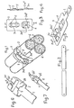
- the device comprises a strap 1 of bendable strip metal, conveniently 0.5 mms thick type 316 stainless steel, and a buckle plate 2, conveniently made of the same material 0.889 mms thick, and stamped to form a raised bridge portion 3 providing a passage beneath the bridge which is wider than the width of the strip steel forming the strap, the underside of the flat top of the bridge preferably being spaced from the surface of the plate by slightly less than the thickness of the strip.
- Slots 5 which may be defined by extensions of the opening produced by stamping up the bridge portion 3, are formed at opposite ends of the plate. Opposite ends of the slots may be formed downwards as shown to facilitate pushing the strip through the bridge.
- the buckle plate is also formed with a second raised bridge portion which is divided approximately along its centre line to form two fixed ears 3a' and 3a" and is made wider than the bridge 3.
- one end of the strip 1 is passed through the slot 5 nearest an end of the plate, from the raised bridge side of the buckle plate, for a distance of about 2.5 cms, and is folded back on the strip.
- the strip attached to the buckle plate is then wrapped around the cables 6 with the bridge portion 3 facing away from the cables, and the free end of the strip 1 is threaded under the ears 3a' and 3a" and through the passage under the bridge 3.
- the free end of the strip is then first tilted slightly about its axis and is slid through the gap 4 between the fixed ears 3a' and 3a" with its edge inserted beneath one of the ears. It is then pushed sideways until its other edge is clear of the end of the second ear, whereupon the strip is pushed sideways in the opposite direction until its said other edge is engaged below said second ear and the strip is centralised beneath the fixed ears.
- the strip and buckle are now secured.
- the fixing and securing of the strapping is thus a simple ' operation to perform, even under difficult conditions. No bending of the ears is necessary, and consequently damage to the surface finish on the buckle and strip is minimised.
- the overall width between their connections to the buckle 2 should be approximately twice the width of the strip.
- the internal width of the bridge 3 can be 11.2 mm and of the bridge 3a 14.3 mm.
- the free ends 3c of the ears may be bent slightly away from the buckle to form lead-in portions facilitating sideways insertion of the strip beneath the ears.
- the components may be made of mild steel or other suitable material.
- the strap may be attached to the buckle plate by welding, or by stamping it integrally with the buckle plate as shown in Figure 5, in which the buckle plate 2 of the construction shown in Figure 4 is made in one piece with the strip 1.
- the fixed ears 3a' and 3a" may be constituted by ears projecting from the edge of the buckle plate and folded back inwards to their fixed positions with a gap 4 therebetween.
- FIGS 6 and 7 which show modified constructions are particularly suitable for smaller and lighter strapping.
- the buckle portion 2 is integral with the strip 1, and both the bridge 3b and the ears 3b' and 3b" are formed by folding up ear portions from opposite sides of the buckle portion.
- the ear portions forming the bridge 3b may be shaped to form a recess 7 for centralising the strip when it is folded back over the bridge 3b.
- buckle portions of the embodiments of Figures 6 and 7 can also be made as separate buckle plates to which the end of the strap 1 can be attached. It is not essential for the bridge 3 or 3b to be raised above the main body or base of the buckle or buckle portion; it may lie substantially flush with the remainder of the plate forming the buckle.
Landscapes
- Engineering & Computer Science (AREA)
- General Engineering & Computer Science (AREA)
- Mechanical Engineering (AREA)
- Package Frames And Binding Bands (AREA)
Claims (7)
Applications Claiming Priority (6)
| Application Number | Priority Date | Filing Date | Title |
|---|---|---|---|
| GB8210203 | 1982-04-06 | ||
| GB8210203 | 1982-04-06 | ||
| GB08216872A GB2112846A (en) | 1981-06-16 | 1982-06-10 | Device for strapping cables etc. together |
| GB8216872 | 1982-06-10 | ||
| GB08231537A GB2117821B (en) | 1982-04-06 | 1982-11-04 | Device for strapping cables pipes or other similar items together or to supports |
| GB8231537 | 1982-11-04 |
Publications (2)
| Publication Number | Publication Date |
|---|---|
| EP0106861A1 EP0106861A1 (de) | 1984-05-02 |
| EP0106861B1 true EP0106861B1 (de) | 1987-07-22 |
Family
ID=27261548
Family Applications (1)
| Application Number | Title | Priority Date | Filing Date |
|---|---|---|---|
| EP83901209A Expired EP0106861B1 (de) | 1982-04-06 | 1983-04-05 | Vorrichtung zum befestigen von kabeln, rohren oder dergleichen |
Country Status (6)
| Country | Link |
|---|---|
| US (1) | US5007138A (de) |
| EP (1) | EP0106861B1 (de) |
| AU (1) | AU1379183A (de) |
| DE (1) | DE3372653D1 (de) |
| GB (1) | GB2117821B (de) |
| WO (1) | WO1983003656A1 (de) |
Families Citing this family (16)
| Publication number | Priority date | Publication date | Assignee | Title |
|---|---|---|---|---|
| GB2168103B (en) * | 1984-12-11 | 1986-12-31 | Bowthorpe Hellermann Ltd | Tying device |
| US4896402A (en) * | 1988-02-05 | 1990-01-30 | Band-It-Idex, Inc. | Cable tie |
| GB2261019B (en) * | 1991-11-02 | 1994-12-07 | Philip Fields Hayward | Fixing tie |
| US5715580A (en) * | 1996-09-09 | 1998-02-10 | Net/Werk/Usa, Inc. | Strapping system and fastener therefor |
| AU717523B2 (en) * | 1996-11-29 | 2000-03-30 | Spiral Guard Australia Pty Ltd | Hose mounting bracket |
| AUPO394896A0 (en) * | 1996-11-29 | 1997-01-02 | May, Peter Andrew John | Hose mounting bracket |
| GB2385787B (en) * | 2002-02-28 | 2005-07-06 | Spirent Plc | Metal banding tie |
| US20040200042A1 (en) * | 2003-04-14 | 2004-10-14 | Howell Frank A. | Rucksack rapid attachment buckle |
| RU2299662C1 (ru) * | 2005-10-04 | 2007-05-27 | Александр Александрович Храпинский | Замок бандажный |
| US9009923B2 (en) * | 2012-04-02 | 2015-04-21 | Panduit Corp. | Cushion sleeve |
| FR3022598B1 (fr) * | 2014-06-23 | 2016-07-15 | Caillau Ets | Collier de serrage a boucle transversale |
| FR3022531B1 (fr) * | 2014-06-23 | 2016-07-15 | Caillau Ets | Collier de serrage a boucle transversale |
| CN105276305A (zh) * | 2015-08-27 | 2016-01-27 | 无锡一名精密铜带有限公司 | 一种新型高压化肥专用管 |
| CN105065897A (zh) * | 2015-08-27 | 2015-11-18 | 无锡一名精密铜带有限公司 | 一种新型石油裂化管 |
| GB2574671A (en) * | 2018-06-15 | 2019-12-18 | D Line Europe Ltd | Conduit clip |
| US20250302184A1 (en) * | 2024-03-26 | 2025-10-02 | Haley Strategic Partners, LLC | Attachment mechanism |
Family Cites Families (20)
| Publication number | Priority date | Publication date | Assignee | Title |
|---|---|---|---|---|
| US211525A (en) * | 1879-01-21 | Improvement in colors derived from nitraniline | ||
| US180388A (en) * | 1876-07-25 | Improvement in bale-ties | ||
| US69849A (en) * | 1867-10-15 | sheppaed | ||
| US653337A (en) * | 1900-05-07 | 1900-07-10 | Sinclair Taliaferro | Bale-band fastening. |
| US834758A (en) * | 1906-04-11 | 1906-10-30 | Walter Ross Sr | Bale-buckle. |
| US1855007A (en) * | 1930-11-20 | 1932-04-19 | Boabands Ltd | Fastener for bands and the like |
| US2011634A (en) * | 1933-09-21 | 1935-08-20 | Adjusta Company | Adjustable strap fastening |
| US2192979A (en) * | 1937-09-08 | 1940-03-12 | Jr Michael J Mcaneny | Hose clamp |
| FR710993A (fr) * | 1938-11-25 | 1931-09-01 | Pince à ligaturer | |
| US2286159A (en) * | 1939-08-19 | 1942-06-09 | Remington Arms Co Inc | Article sealing and labeling machine |
| US2293562A (en) * | 1940-01-11 | 1942-08-18 | Maiden Form Brassiere Company | Buckle |
| GB570492A (en) * | 1943-07-09 | 1945-07-10 | Uniqlip Ltd | Improvements in or relating to end fastenings for straps |
| US2377224A (en) * | 1943-09-09 | 1945-05-29 | John M Gerrard | Seal |
| US2407466A (en) * | 1944-04-15 | 1946-09-10 | Leon N Alberts | Clasp |
| US2473209A (en) * | 1947-05-22 | 1949-06-14 | Lombardi Cyrus | Buckle |
| GB709133A (en) * | 1951-08-27 | 1954-05-19 | Steels & Busks Ltd | Improvements in buckles |
| US2759233A (en) * | 1952-01-16 | 1956-08-21 | Acme Steel Co | Strap seal and method of applying same |
| US2914827A (en) * | 1958-04-15 | 1959-12-01 | Lewis M Schott | Metal strap fastening means |
| BE627196A (de) * | 1962-12-18 | |||
| CH594821A5 (de) * | 1976-12-23 | 1978-01-31 | Edmund B Woringer |
-
1982
- 1982-11-04 GB GB08231537A patent/GB2117821B/en not_active Expired
-
1983
- 1983-04-05 AU AU13791/83A patent/AU1379183A/en not_active Abandoned
- 1983-04-05 WO PCT/GB1983/000102 patent/WO1983003656A1/en not_active Ceased
- 1983-04-05 EP EP83901209A patent/EP0106861B1/de not_active Expired
- 1983-04-05 DE DE8383901209T patent/DE3372653D1/de not_active Expired
-
1986
- 1986-08-25 US US06/899,947 patent/US5007138A/en not_active Expired - Lifetime
Also Published As
| Publication number | Publication date |
|---|---|
| GB2117821A (en) | 1983-10-19 |
| GB2117821B (en) | 1985-10-23 |
| WO1983003656A1 (en) | 1983-10-27 |
| AU1379183A (en) | 1983-11-04 |
| US5007138A (en) | 1991-04-16 |
| DE3372653D1 (en) | 1987-08-27 |
| EP0106861A1 (de) | 1984-05-02 |
Similar Documents
| Publication | Publication Date | Title |
|---|---|---|
| US5007138A (en) | Device for strapping cables, pipes or other similar items, together or to supports | |
| US5759004A (en) | MLT bent leg pushmount | |
| EP0618086B1 (de) | Verbesserungen an oder bezüglich der Ringschienenteile einer Ringbuchmechanik | |
| US4543691A (en) | Hose clamp | |
| US5332179A (en) | 2-way box mount | |
| EP0328305B1 (de) | Kabelbinder | |
| JP2006084033A (ja) | リベット連結装置 | |
| JPH0231570B2 (de) | ||
| HU212330B (en) | Arrangement particularly for connecting of the two ends of a clamp | |
| AU680956B2 (en) | Mounting device | |
| SK281436B6 (sk) | Svorka | |
| US6471552B2 (en) | Spring for securing a terminal block or the like to a rail | |
| GB2112846A (en) | Device for strapping cables etc. together | |
| CA1284573C (en) | Device for strapping cables, pipes or other similar items, together or to supports | |
| US5810305A (en) | Mounting device for securing an object to a post | |
| US4446604A (en) | Wrist bracelet clasp | |
| EP0731889B1 (de) | Rohrschelle | |
| GB2168103A (en) | Tying device | |
| CA2139290C (en) | Cover for a fuel tank support strap | |
| JPH0213594Y2 (de) | ||
| JP2544864Y2 (ja) | ベルトクランプ | |
| JPH0610144U (ja) | 取っ手 | |
| JP3692505B2 (ja) | 上折り曲げ付カバー | |
| JPS6011288Y2 (ja) | ケ−ブル等の取付用座付きサドル | |
| JPH01503635A (ja) | 固定要素 |
Legal Events
| Date | Code | Title | Description |
|---|---|---|---|
| PUAI | Public reference made under article 153(3) epc to a published international application that has entered the european phase |
Free format text: ORIGINAL CODE: 0009012 |
|
| AK | Designated contracting states |
Designated state(s): DE FR NL SE |
|
| 17P | Request for examination filed |
Effective date: 19840427 |
|
| GRAA | (expected) grant |
Free format text: ORIGINAL CODE: 0009210 |
|
| AK | Designated contracting states |
Kind code of ref document: B1 Designated state(s): DE FR NL SE |
|
| REF | Corresponds to: |
Ref document number: 3372653 Country of ref document: DE Date of ref document: 19870827 |
|
| ET | Fr: translation filed | ||
| PLBE | No opposition filed within time limit |
Free format text: ORIGINAL CODE: 0009261 |
|
| STAA | Information on the status of an ep patent application or granted ep patent |
Free format text: STATUS: NO OPPOSITION FILED WITHIN TIME LIMIT |
|
| 26N | No opposition filed | ||
| EAL | Se: european patent in force in sweden |
Ref document number: 83901209.3 |
|
| PGFP | Annual fee paid to national office [announced via postgrant information from national office to epo] |
Ref country code: FR Payment date: 20010423 Year of fee payment: 19 |
|
| PGFP | Annual fee paid to national office [announced via postgrant information from national office to epo] |
Ref country code: NL Payment date: 20010424 Year of fee payment: 19 |
|
| PGFP | Annual fee paid to national office [announced via postgrant information from national office to epo] |
Ref country code: SE Payment date: 20010427 Year of fee payment: 19 |
|
| PGFP | Annual fee paid to national office [announced via postgrant information from national office to epo] |
Ref country code: DE Payment date: 20010502 Year of fee payment: 19 |
|
| PG25 | Lapsed in a contracting state [announced via postgrant information from national office to epo] |
Ref country code: SE Free format text: LAPSE BECAUSE OF NON-PAYMENT OF DUE FEES Effective date: 20020406 |
|
| PG25 | Lapsed in a contracting state [announced via postgrant information from national office to epo] |
Ref country code: NL Free format text: LAPSE BECAUSE OF NON-PAYMENT OF DUE FEES Effective date: 20021101 Ref country code: DE Free format text: LAPSE BECAUSE OF NON-PAYMENT OF DUE FEES Effective date: 20021101 |
|
| EUG | Se: european patent has lapsed |
Ref document number: 83901209.3 |
|
| PG25 | Lapsed in a contracting state [announced via postgrant information from national office to epo] |
Ref country code: FR Free format text: LAPSE BECAUSE OF NON-PAYMENT OF DUE FEES Effective date: 20021231 |
|
| NLV4 | Nl: lapsed or anulled due to non-payment of the annual fee |
Effective date: 20021101 |
|
| REG | Reference to a national code |
Ref country code: FR Ref legal event code: ST |