EP0106898B1 - Mikrowellenofen - Google Patents
Mikrowellenofen Download PDFInfo
- Publication number
- EP0106898B1 EP0106898B1 EP82901308A EP82901308A EP0106898B1 EP 0106898 B1 EP0106898 B1 EP 0106898B1 EP 82901308 A EP82901308 A EP 82901308A EP 82901308 A EP82901308 A EP 82901308A EP 0106898 B1 EP0106898 B1 EP 0106898B1
- Authority
- EP
- European Patent Office
- Prior art keywords
- heating
- high frequency
- weight
- food
- output
- Prior art date
- Legal status (The legal status is an assumption and is not a legal conclusion. Google has not performed a legal analysis and makes no representation as to the accuracy of the status listed.)
- Expired
Links
- 235000013305 food Nutrition 0.000 claims abstract description 23
- 238000010438 heat treatment Methods 0.000 claims description 108
- 244000144977 poultry Species 0.000 abstract description 4
- 235000015278 beef Nutrition 0.000 abstract description 2
- 238000010411 cooking Methods 0.000 description 14
- 235000013594 poultry meat Nutrition 0.000 description 9
- 241000287828 Gallus gallus Species 0.000 description 8
- 238000004804 winding Methods 0.000 description 8
- 230000002093 peripheral effect Effects 0.000 description 5
- 238000000034 method Methods 0.000 description 4
- 238000012545 processing Methods 0.000 description 4
- 230000005540 biological transmission Effects 0.000 description 2
- 239000000470 constituent Substances 0.000 description 2
- 238000007796 conventional method Methods 0.000 description 2
- 230000001419 dependent effect Effects 0.000 description 2
- 230000000694 effects Effects 0.000 description 2
- 239000000463 material Substances 0.000 description 2
- 230000010355 oscillation Effects 0.000 description 2
- 230000005855 radiation Effects 0.000 description 2
- 239000000126 substance Substances 0.000 description 2
- 239000003990 capacitor Substances 0.000 description 1
- 238000010276 construction Methods 0.000 description 1
- 238000001816 cooling Methods 0.000 description 1
- 230000007423 decrease Effects 0.000 description 1
- 230000003247 decreasing effect Effects 0.000 description 1
- 238000013461 design Methods 0.000 description 1
- 238000010586 diagram Methods 0.000 description 1
- 238000002474 experimental method Methods 0.000 description 1
- 235000015277 pork Nutrition 0.000 description 1
Images


Classifications
-
- H—ELECTRICITY
- H05—ELECTRIC TECHNIQUES NOT OTHERWISE PROVIDED FOR
- H05B—ELECTRIC HEATING; ELECTRIC LIGHT SOURCES NOT OTHERWISE PROVIDED FOR; CIRCUIT ARRANGEMENTS FOR ELECTRIC LIGHT SOURCES, IN GENERAL
- H05B6/00—Heating by electric, magnetic or electromagnetic fields
- H05B6/64—Heating using microwaves
- H05B6/66—Circuits
- H05B6/68—Circuits for monitoring or control
- H05B6/687—Circuits for monitoring or control for cooking
Definitions
- a high frequency output is generally selected based upon the kind of heating load in carrying out high frequency heating and cooking.
- the high frequency output selected is dependent upon the constituent materials or substances of the heating load.
- cooking time is determined by the high frequency output selected and the weight of the heating load. Therefore, while preparing the heating load and consulting a cook book, the user may select, calculate or determine the high frequency output and heating time in view of the kind and weight of the heating load.
- the cook book generally discusses a full range of high frequency outputs and cooking times appropriate to all of the different kinds and weights of the. heating loads which have been derived from preliminary or well established experiments. It is customary practice to enter those appropriate high frequency outputs and cooking times on a keyboard of the appliance.
- the conventional appliance requires a very complicated procedure and results in an increased possibility of faulty operation and inconvenience in use.
- the microcomputer is programmed to permit all possible combinations of the high frequency output and the heating time to be established.
- the capacity of a ROM in the microcomputer should be very large.
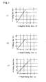
- FIG. 1 shows some examples of chicken often cooked in American homes.
- Fig. 1 shows some examples of chicken often cooked in American homes.
- chicken which are widely cooked in American homes: Cornish hen, chicken and turkey. It is appreciated that the high frequency outputs and heating times which are necessary to cook those kinds of poultry meat are as follows:
- Figs. 1A, 1 B and 1C The relationships among the weight of the heating load, the heating time and the high frequency output in those cases are depicted in Figs. 1A, 1 B and 1C.
- the user of the conventional appliance finds the optimum value of high frequency output and that of heating time from the book and introduces these values through high frequency output setting pads and heating time setting pads.
- the user should calculate the heating time setting by multiplying the weight of the heating load by a unit time as shown in the book.
- FIG. 2 An improved high frequency heating appliance of which a flow chart is illustrated in Fig. 2 has been suggested.
- the heating load is grouped into major classes and sub-classes as follows:
- weight brackets having its unique constants assigned thereto assure approximate values of heating time.
- the weight brackets are usually equally spaced and, for example, every 2 kg against a maximum of 6 kg.
- a total of 18 constants determinative of weight-to-time relationship a 1 , a 12 , a 13 , a 2 ...a 53 , b 1 , b 12 ...b 52 are required since the same weight brackets apply to the sub-class.
- a greater number of the major classes or sub-classes would cause a remarkable increase in the number of the constants and therefore the capacity of a ROM contained in a microcomputer.
- EP-A-0029483 discloses a high frequency heating apparatus comprising a heating chamber to receive food, a high frequency oscillator to heat the food by radiating high frequency waves into said heating chamber, a control circuit unit including a microcomputer having a program function and a control function to control the output of waves of said high frequency oscillator, selection keys to select a major classification of the food in the chamber and feed this information into said control circuit unit, and a weight key to feed the weight of the food into said control circuit unit.
- EP-A-0029483 discloses the use of a means for remotely sensing the power absorbed by the food and varies the cooking time in response thereto.
- the disadvantage of such an arrangement is that of additional complication and expense.
- the present invention seeks to overcome these disadvantages by relying on the use of a stored lock up table within a microcomputer, but wherein the number of constants employed are reduced as compared with known arrangements.
- the present invention is characterised in that the control circuit unit possesses a means to determine a minor classification of the food from the information of the major classification of the food from said selection keys and the information of the weight of the food from said weight key and a setting means to set the output of the waves and heating time T from the information of the minor classification and the information of the weight from said weight key, and said heating time T is determined in the following formula, supposing the constants set by the information of the minor classification from said judging means to be a, b and the weight of the food to be W: where i is the major classification and j is the minor classification.
- the heating load has its unique weight range primarily depending upon the sub-class thereof.
- the kind of the heating load is suggested predominantly by the weight thereof when determined.
- the optimum amount of heating time is decided primarily and automatically as long as the weight and kind of the heating load are already known.
- the optimum amount of high frequency output is dependent upon the constituent materials or substances of the heating load and in other words upon the kind (sub-class) of the heating load.
- weight brackets of the heating loads one of predominant factors of determining heating output and time, as stored in a program in a microcomputer, are brought into well agreement with usual weight ranges of, for example, poultry covering Cornish hen, chicken and turkey.
- a selected one of heating outputs is preset for each of the weight brackets which correspond to the major classes of the heating load.
- the high frequency output and the heating time are determined automatically predominantly by specifying the major class and the weight of the heating load, so that heating is effected with the optimum high frequency output and the heating time which are both most suitable for the sub-class of the heating load.
- the user may conduct cooking operation at the high frequency output and heating time most suitable for the sub-class of the heating load, merely by selecting the major classes of the heating load generally known to the public and setting the weight of the heating load (i.e., without the need to select the high frequency output and the heating time or retrieve the sub-class of the heating load).
- the present appliance is therefore very easy to operate and convenient to use without the need to consult the cook book.
- the present appliance requires only a series combination of these two factors in programming the microcomputer and permits the use of a cost-saving microcomputer with a decreased requirement for ROM capacity.
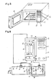
- a high frequency heating appliance is shown referring to Figs. 4 to 6.
- a high frequency oscillator 1 of the design that provides microwave oscillation at 2450 MHz is coupled via a metal-made waveguide 2 and an antenna 3.
- High frequency waves from the high frequency oscillator 1 is directed into the waveguide 2 and radiated toward the interior of a heating chamber 4 after traveling through the waveguide 2.
- the high frequency waves effect dielectric heating on food 5 from inside while being absorbed by the food 5 mounted within the heating chamber 4.
- the high frequency oscillator 1 is subject to self-heating due to its internal loss and is therefore cooled by a blower fan 6 to prevent faulty operation during oscillation.
- air fed via the blower fan passes through perforations 7 in a wall of the heating chamber 4 and enters the heating chamber 4.
- the air in the heating chamber 4 traverses perforations 8 in a wall of the heating chamber 4 while carrying stream generated from the food 5 during high frequency heating. Further, the air is discharged to the exterior of the high frequency heating appliance after traveling through the heating chamber 4 and a drain guide 9 communicating between the interior and exterior of the high frequency heating appliance.
- a control panel 10 as shown in Fig. 5 carries a keyboard 12 including a plurality of key pads 11 manually operable by the user for introducing heating output, heating time and heating mode settings and display elements 13 such as LEDs and fluorescent display tubes for displaying the heating output, time and mode settings.
- a freely openable and closable door 14 provides access to the heating chamber 4 for the food 5.
- a control circuit of the high frequency heating appliance will not be described by reference to Fig. 6.
- the high frequency heating appliance is usually plugged into a plug receptacle in a house for power supply via a power plug.
- One end 15 of the power plug is connected to a fuse 16 which will fuse in response to operation of a short switch for preventing leakage of a substantial amount of microwaves if any electric components of the high frequency heating appliance is short-circuited or grounded or an interlock as described below becomes melted.
- the interlock 17 whose contact is opened and closed upon opening and closing movement of the door 14 is connected to the fuse 16.
- the interlock 17 is also connected to reply 19 which is switched on to ihterrupt heating in response to a heating start command from a microcomputer 18 and switched off in response to an end or halt command from the same.
- the relay 19 is connected to a second interlock 20 whose contact is opened and closed upon movement of the door 14 for provision of doubled safeguard.
- the interlock 20 is connected to a primary winding 22 of a high voltage transformer 21. Connected across the primary winding 22 of the high voltage transformer 21 are the cooling fan 6 and the above mentioned short switch 23 which works to render the whole of the circuit inoperable when the interlock 17 or 20 becomes melted.
- the remaining end 24 of the power plug is connected directly to the primary winding 22 of the high voltage transformer 21.
- An AC power input to the high voltage transformer 21 is boosted into a high voltage power output through operation of the high voltage transformer 21.
- the resultant high voltage power output is multiplied and rectified into a high voltage DC power output through a voltage multiplier and rectifier composed of a high voltage capacitor 25 and a high voltage diode 26.
- the high voltage DC power output is fed to the high frequency oscillator 1 via a high voltage switch 27 switchable in a given cycle, to thereby permit the amount of the high frequency output to be variable.
- the high voltage DC power output supplied to the high frequency oscillator 1 is converted into high frequency radiations in the high frequency oscillator 1 and the radiations are delivered from the antenna 3.
- the high frequency waves serve to heat the food 5 in the above described manner.
- the high voltage transformer 21 further includes a heater winding 28 and a biquadratic winding 29, with the heater winding 28 leading to a heater 30 of the high frequency oscillator 1 for heating the heater.
- the function of the biquadratic winding 29 is to find that the door 14 has been opened in the course of heating and the interlocks 17 and 20 have been switched off to interrupt AC power supply to the high voltage transformer 21 and to inform the microcomputer 18 of this finding and eventually disenergize the relay 19. It is noted that the high voltage switch 27 are switched on and off at the given interval in response to commands from the microcomputer 18 when heating output is set upon the user's actuation of the output setting key.
- the microcomputer 18 plays an important role in the whole of the control circuit.
- the primary function of the microcomputer 18 is to control peripheral circuits, analyze and calculate information from the peripheral circuits and then control the peripheral circuits according to the results of such analysis and calculation.
- the microcomputer 18 is set up by input terminals 31 for receipt of information characteristic of selected ones of heating output, time and modes as introduced via the keyboard 12, a cooking interruption command from the biquadratic winding 29 of the high voltage transformer 21, etc.; an accumulator 32 for temporarily storing the commands, the information, etc.
- ROM 33 for storing all of the commands and information necessary for controlling the whole system
- RAM 34 for storing the information and data fed from the input terminals 31
- central processing unit 35 for analyzing and calculating the information, data and various commands
- output terminals 36 for delivering output signals for controlling the peripheral circuits according to the resultant data.
- the output terminals 36 of the microcomputer 18 feed the output signals to the input terminals 37 on the keyboard 12 so that output signals will be available at the keypads 11 on the keyboard 12.
- a signal received by an input terminal 31 is temporarily loaded into the accumulator 32 via the input terminals 31 of the microcomputer 18 for subsequent comparison with the data in the ROM 33, transmission to the RAM 34 or the central processing unit 35 and calculation in the central processing unit 35. If the case permits, signals resulting from the calculation are transferred from the output terminal 36 to the peripheral circuits such as the display 13, the relay 19 and the high voltage switch 29 to enable the same.
- Actuations of the keyboard 12 by the user and in other words information characteristic of the heating time and high frequency output settings is fed into the microcomputer 18, thus opening and closing the relay 19 in response to the heating time settings and switching on and off the high voltage switch 27 in response to the high frequency output settings.
- the output terminals 39 of the microcomputer 18 deliver the output signals to the display tubes 13 on the control panel 10 for the purpose of displaying the cooking output, time and modes settings.
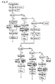
- Fig. 7 shows a flow chart drawn in conjunction with the microcomputer 18.
- Fig. 8 graphically represents the contents of the ROM in the microcomputer 18.
- weight brackets "0.15-0.7-kg", “0.7-1.5 kg” and "1.5-5.8 kg”. These weight brackets correspond to the actual weights of the load in the sub-classes “Cornish hen", “chicken” and “turkey” in the case of chicken. For example, “Cornish hen” which is widely used in home cooking falls within a weight range of "0.15 to 0.7 kg”.
- the optimum heating conditions for each of these weight brackets are established by heating outputs W 1 , W 2 ,...W 5 (in watts) and constants a 1 , a 12 ,...a 53 and b 1 , b 12 ,...b 52 which define heating time slots T 1 , T 2 ,...T 5 .
- W 1 , W 2 ,...W 5 in watts
- constants a 1 , a 12 ,...a 53 and b 1 , b 12 ,...b 52 which define heating time slots T 1 , T 2 ,...T 5 .
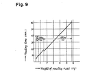
- Fig. 9 typically shows the relationship among the weight of poultry meat, heating output and heating time, in which heating is effected with a heating time as determined by a graph plotted with a straight line in zone "a" and 700 watts of output when weight is inputted within a range of "0.15 to 0.7 kg".
- the high frequency heating appliance embodying the present invention applicable as microwave ovens for home or business use is adapted such that it performs automatic determinations as to high frequency output and heating time if the kind (major class) and the actual weight of the heating load are keyed in.
- the present appliance provides convenience for the user's use, simplicity of the stored program in the microcomputer, minimum numbers of steps to be stored in the ROM and RAM and corresponding decreases in the capacities of the ROM and RAM.
Landscapes
- Physics & Mathematics (AREA)
- Electromagnetism (AREA)
- Electric Ovens (AREA)
- Control Of High-Frequency Heating Circuits (AREA)
Claims (2)
Applications Claiming Priority (1)
| Application Number | Priority Date | Filing Date | Title |
|---|---|---|---|
| PCT/JP1982/000149 WO1983003889A1 (en) | 1982-04-30 | 1982-04-30 | Microwave oven |
Publications (3)
| Publication Number | Publication Date |
|---|---|
| EP0106898A1 EP0106898A1 (de) | 1984-05-02 |
| EP0106898A4 EP0106898A4 (de) | 1984-09-06 |
| EP0106898B1 true EP0106898B1 (de) | 1987-07-01 |
Family
ID=13762240
Family Applications (1)
| Application Number | Title | Priority Date | Filing Date |
|---|---|---|---|
| EP82901308A Expired EP0106898B1 (de) | 1982-04-30 | 1982-04-30 | Mikrowellenofen |
Country Status (6)
| Country | Link |
|---|---|
| US (1) | US4629848A (de) |
| EP (1) | EP0106898B1 (de) |
| AU (1) | AU552208B2 (de) |
| CA (1) | CA1193328A (de) |
| DE (1) | DE3276669D1 (de) |
| WO (1) | WO1983003889A1 (de) |
Families Citing this family (16)
| Publication number | Priority date | Publication date | Assignee | Title |
|---|---|---|---|---|
| JP2589592B2 (ja) * | 1990-10-22 | 1997-03-12 | シャープ株式会社 | 電子レンジ |
| KR930011809B1 (ko) * | 1990-12-18 | 1993-12-21 | 주식회사 금성사 | 전자레인지의 자동요리방법 및 그 장치 |
| JPH04244521A (ja) * | 1991-01-29 | 1992-09-01 | Toshiba Corp | 加熱調理器 |
| KR930007513B1 (ko) * | 1991-04-01 | 1993-08-12 | 주식회사 금성사 | 전자레인지의 요리완료시간 예약방법 |
| TR25844A (tr) * | 1991-12-27 | 1993-09-01 | Gold Star Co | Bir mikro dalga firininda otomatik pisirme icin yöntem ve aygit. |
| US5321232A (en) * | 1992-01-03 | 1994-06-14 | Amana Refrigeration, Inc. | Oven controlled by an optical code reader |
| FR2701093B1 (fr) * | 1993-02-02 | 1995-04-14 | Moulinex Sa | Appareil de cuisson comportant un dispositif de dorage et un dispositif de génération d'énergie micro-ondes et procédé de commande de cuisson d'un tel appareil . |
| FR2703481B1 (fr) * | 1993-04-01 | 1995-05-12 | Moulinex Sa | Four de cuisson et son tableau de commande. |
| KR0129228B1 (ko) * | 1994-04-01 | 1998-04-09 | 구자홍 | 마이크로웨이브오븐의 자동조리 제어방법 및 장치 |
| EP0688146B1 (de) * | 1994-06-13 | 2000-04-26 | Whirlpool Europe B.V. | Verfahren zum Steueren eines Mikrowellenofens, Mikrowellenofen und seine Verwendung zum Kochen oder Erwarmen eines Nahrungmittels nach diesem Verfahren |
| EP0792083B1 (de) * | 1996-02-23 | 1999-07-28 | Samsung Electronics Co., Ltd. | Verfahren zum Steuern eines Mikrowellenofens zum Vermeiden des Übergarens kleiner Speiseportionen |
| KR970062531A (ko) * | 1996-02-23 | 1997-09-12 | 김광호 | 전자렌지의 구동제어방법 |
| US5812393A (en) * | 1996-05-14 | 1998-09-22 | Microwave Science, Llc | Interpretive BIOS machine and method of use thereof |
| US5883801A (en) * | 1996-05-14 | 1999-03-16 | Microwave Science, Llc | Method and apparatus for managing electromagnetic radiation usage |
| CN103120548B (zh) * | 2011-11-18 | 2016-08-03 | 乐金电子(天津)电器有限公司 | 食物烘烤一键制控制方法 |
| CN109253475B (zh) * | 2018-09-27 | 2020-07-03 | 广东美的厨房电器制造有限公司 | 控制方法、烹饪设备和计算机可读存储介质 |
Family Cites Families (8)
| Publication number | Priority date | Publication date | Assignee | Title |
|---|---|---|---|---|
| JPS592802B2 (ja) * | 1978-09-25 | 1984-01-20 | シャープ株式会社 | 加熱調理器 |
| JPS5582236A (en) * | 1978-12-14 | 1980-06-20 | Sanyo Electric Co Ltd | Cooking range with electronic controller |
| JPS56935A (en) * | 1979-06-15 | 1981-01-08 | Matsushita Electric Ind Co Ltd | High-frequency heating device |
| JPS5613692A (en) * | 1979-07-11 | 1981-02-10 | Matsushita Electric Industrial Co Ltd | High frequency heater |
| JPS5620931A (en) * | 1979-07-27 | 1981-02-27 | Sanyo Electric Co Ltd | Electronically controlled cooker |
| US4317977A (en) * | 1979-09-06 | 1982-03-02 | Litton Systems, Inc. | Power controlled microwave oven |
| US4447693A (en) * | 1979-09-06 | 1984-05-08 | Litton Systems, Inc. | Power controlled microwave oven |
| US4413168A (en) * | 1980-09-24 | 1983-11-01 | Raytheon Company | Heating time coupling factor for microwave oven |
-
1982
- 1982-04-30 AU AU83370/82A patent/AU552208B2/en not_active Expired
- 1982-04-30 US US06/819,009 patent/US4629848A/en not_active Expired - Lifetime
- 1982-04-30 DE DE8282901308T patent/DE3276669D1/de not_active Expired
- 1982-04-30 EP EP82901308A patent/EP0106898B1/de not_active Expired
- 1982-04-30 WO PCT/JP1982/000149 patent/WO1983003889A1/ja not_active Ceased
-
1983
- 1983-01-25 CA CA000420149A patent/CA1193328A/en not_active Expired
Also Published As
| Publication number | Publication date |
|---|---|
| EP0106898A4 (de) | 1984-09-06 |
| AU552208B2 (en) | 1986-05-22 |
| US4629848A (en) | 1986-12-16 |
| DE3276669D1 (en) | 1987-08-06 |
| CA1193328A (en) | 1985-09-10 |
| EP0106898A1 (de) | 1984-05-02 |
| WO1983003889A1 (en) | 1983-11-10 |
| AU8337082A (en) | 1983-11-21 |
Similar Documents
| Publication | Publication Date | Title |
|---|---|---|
| EP0106898B1 (de) | Mikrowellenofen | |
| US4520251A (en) | Method for operating a programmable microwave heating apparatus with food defrosting control | |
| US4463238A (en) | Combined microwave and electric heating oven selectively controlled by gas sensor output and thermistor output | |
| CA1166704A (en) | Heating apparatus provided with a voice synthesizing circuit | |
| US6689996B2 (en) | Microwave oven and method of controlling thereof | |
| EP1021066B1 (de) | Verfahren zum Betreiben eines Mikrowellenofens | |
| US4572935A (en) | Cooking apparatus having an initial temperature setting function | |
| CA2459604A1 (en) | Methods and apparatus for operating a speedcooking oven | |
| US3480753A (en) | Electronic oven | |
| DE4444778A1 (de) | Mikrowellenofen mit einer Induktionsheizfunktion sowie ein dazu geeignetes Steuerverfahren | |
| EP0688147B1 (de) | Verfahren zur Regelung eines Mikrowellenofens, Mikrowellenofen und seine Anwendung für Kochen oder Wärmung von Essen gemäss dem Verfahren | |
| CA1093647A (en) | Minimizing lamp flicker and blower speed variation in a microwave oven employing duty cycle power level control | |
| US3961152A (en) | Magnetron power supply and control circuit | |
| KR20040047079A (ko) | 가열조리장치 및 그 제어방법 | |
| US6448541B1 (en) | AC/DC type microwave oven | |
| CA1193673A (en) | High frequency heating appliance for effecting automatically preprogrammed cooking | |
| EP0688146A2 (de) | Verfahren zum Steueren eines Mikrowellenofens, Mikrowellenofen und seine Verwendung zum Kochen oder Erwarmen eines Nahrungmittels nach diesem Verfahren | |
| US4345135A (en) | Delay-start arrangement for a microwave oven | |
| CA1175913A (en) | High frequency heating appliance | |
| JPWO1983003889A1 (ja) | 高周波加熱装置 | |
| KR100259152B1 (ko) | 전자렌지의 부하 자동검출장치 | |
| KR0182525B1 (ko) | 복합조리기의 구동제어장치 및 그 구동제어방법 | |
| KR102817476B1 (ko) | 전자 레인지 | |
| KR19990058209A (ko) | 전자렌지의 중량별 해동 제어방법 | |
| KR0138559B1 (ko) | 전자렌지의 출력변환장치 |
Legal Events
| Date | Code | Title | Description |
|---|---|---|---|
| PUAI | Public reference made under article 153(3) epc to a published international application that has entered the european phase |
Free format text: ORIGINAL CODE: 0009012 |
|
| 17P | Request for examination filed |
Effective date: 19831219 |
|
| AK | Designated contracting states |
Kind code of ref document: A1 Designated state(s): DE FR GB SE |
|
| GRAA | (expected) grant |
Free format text: ORIGINAL CODE: 0009210 |
|
| AK | Designated contracting states |
Kind code of ref document: B1 Designated state(s): DE FR GB SE |
|
| ET | Fr: translation filed | ||
| REF | Corresponds to: |
Ref document number: 3276669 Country of ref document: DE Date of ref document: 19870806 |
|
| PLBE | No opposition filed within time limit |
Free format text: ORIGINAL CODE: 0009261 |
|
| STAA | Information on the status of an ep patent application or granted ep patent |
Free format text: STATUS: NO OPPOSITION FILED WITHIN TIME LIMIT |
|
| 26N | No opposition filed | ||
| EAL | Se: european patent in force in sweden |
Ref document number: 82901308.5 |
|
| REG | Reference to a national code |
Ref country code: GB Ref legal event code: 746 Effective date: 19951123 |
|
| REG | Reference to a national code |
Ref country code: FR Ref legal event code: D6 |
|
| PGFP | Annual fee paid to national office [announced via postgrant information from national office to epo] |
Ref country code: SE Payment date: 20010404 Year of fee payment: 20 |
|
| PGFP | Annual fee paid to national office [announced via postgrant information from national office to epo] |
Ref country code: FR Payment date: 20010409 Year of fee payment: 20 |
|
| PGFP | Annual fee paid to national office [announced via postgrant information from national office to epo] |
Ref country code: DE Payment date: 20010423 Year of fee payment: 20 |
|
| PGFP | Annual fee paid to national office [announced via postgrant information from national office to epo] |
Ref country code: GB Payment date: 20010425 Year of fee payment: 20 |
|
| REG | Reference to a national code |
Ref country code: GB Ref legal event code: IF02 |
|
| PG25 | Lapsed in a contracting state [announced via postgrant information from national office to epo] |
Ref country code: GB Free format text: LAPSE BECAUSE OF EXPIRATION OF PROTECTION Effective date: 20020429 |
|
| REG | Reference to a national code |
Ref country code: GB Ref legal event code: PE20 Effective date: 20020429 |
|
| EUG | Se: european patent has lapsed |
Ref document number: 82901308.5 |