EP0107295A2 - Système d'enregistrement et de reproduction du type vidéodisque - Google Patents
Système d'enregistrement et de reproduction du type vidéodisque Download PDFInfo
- Publication number
- EP0107295A2 EP0107295A2 EP83304991A EP83304991A EP0107295A2 EP 0107295 A2 EP0107295 A2 EP 0107295A2 EP 83304991 A EP83304991 A EP 83304991A EP 83304991 A EP83304991 A EP 83304991A EP 0107295 A2 EP0107295 A2 EP 0107295A2
- Authority
- EP
- European Patent Office
- Prior art keywords
- audio
- output
- frequency
- signal
- pass filter
- Prior art date
- Legal status (The legal status is an assumption and is not a legal conclusion. Google has not performed a legal analysis and makes no representation as to the accuracy of the status listed.)
- Granted
Links
Images


Classifications
-
- G—PHYSICS
- G11—INFORMATION STORAGE
- G11B—INFORMATION STORAGE BASED ON RELATIVE MOVEMENT BETWEEN RECORD CARRIER AND TRANSDUCER
- G11B20/00—Signal processing not specific to the method of recording or reproducing; Circuits therefor
- G11B20/10—Digital recording or reproducing
- G11B20/10527—Audio or video recording; Data buffering arrangements
-
- H—ELECTRICITY
- H04—ELECTRIC COMMUNICATION TECHNIQUE
- H04N—PICTORIAL COMMUNICATION, e.g. TELEVISION
- H04N5/00—Details of television systems
- H04N5/76—Television signal recording
- H04N5/91—Television signal processing therefor
- H04N5/92—Transformation of the television signal for recording, e.g. modulation, frequency changing; Inverse transformation for playback
- H04N5/9201—Transformation of the television signal for recording, e.g. modulation, frequency changing; Inverse transformation for playback involving the multiplexing of an additional signal and the video signal
- H04N5/9202—Transformation of the television signal for recording, e.g. modulation, frequency changing; Inverse transformation for playback involving the multiplexing of an additional signal and the video signal the additional signal being a sound signal
- H04N5/9204—Transformation of the television signal for recording, e.g. modulation, frequency changing; Inverse transformation for playback involving the multiplexing of an additional signal and the video signal the additional signal being a sound signal using frequency division multiplex
Definitions
- the present invention relates to a video disc type recording and reproducing system with multiplexed video and audio signals, and, more particularly, to such a system in which interference between sidebands of the frequency-modulated video signal and the frequency-modulated audio signal is eliminated.
- a video disc type recording and reproducing system typically comprises recording means and reproducing means the recording means comprising a first frequency modulator for modulating a video signal, a second frequency modulator for modulating an audio signal, an adder circuit for adding the modulated video and audio signals, a limiter connected to an output of the adder circuit for pulse width modulating the output signal from the adder circuit, and an electrical/optical modulator connected to the limiter.
- such a system is modified by introducing filter means connected between an output of the first frequency modulator and the adder circuit for removing a frequency component of the frequency-modulated video signal which covers a frequency component of the frequency modulated audio signal from the second frequency modulator to prevent second and higher order sidebands of the modulated video signal interfering with the audio signal multiplexed with it.
- the lower one of the secondary sidebands of the video RF signal which overlaps the audio carrier frequencies, is removed by the filter means so that the audio signals are not influenced thereby.
- the elimination of the secondary or higher order sidebands of the video signal does not affect reproduction of the video signal since the frequency range necessary to reproduce the video signal spans only the primary sideband.
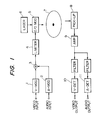
- FIG. 1 Systems in which video information as well as audio information is recorded on a video disc and are simultaneously reproduced are known, and an example thereof is shown in Figure 1.
- a video carrier of, for example, 8.2 MHz is frequency-modulated with the video information by a frequency modulator 1 so that the sync level, the pedestal level and the white peak level thereof become, for example, 7.6 MHz, 8.1 MHz and 9.3 MHz, respectively.
- At least one audio signal is also frequency-modulated by a frequency modulator 2, and outputs of the frequency modulators 1 and 2 are added by an adder circuit 3.
- An output of the adder circuit 3 is supplied to a limiter 4 by which an amplitude of the adder output is limited, and pulse width modulation is performed.
- An output of the limiter is supplied to an electrical/ optical ( E/ O) modulator 5 in which a laser beam from a laser source 6 is modulated by the limiter output, and the resultant signal is recorded on a video disc 7 in a known manner.
- E/ O electrical/ optical
- the recorded information is picked up by a pick-up 8 and amplified by an amplifier 9.
- An output of the amplifier 9 is suitably divided and the resultant video and audio information are detected by detectors 10 and 11, respectively.
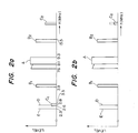
- Figure 2a shows an example of the frequency spectrum of the output of the limiter 4.
- letter A represents the frequency band of the frequency-modulated video signal
- B and B 2 are the primary sidebands thereof
- C 1 and C 2 are the secondary sidebands thereof.
- D and E are audio signal carriers when the audio system is a 2-channel or bilingual system.
- the frequency band width necessary to demodulate the video signal is from 3.9 to 13.5 MHz in the NTSC system in which the primary sidebands are included, because the modulation index is unity or smaller. Therefore, it is usual to set the audio subcarriers at, for example, 2.3 MHz and 2.8 MHz, so that these frequencies are out of the above frequency band necessary for video signal demodulation.
- the secondary sideband of the Y component is from 2.6 to 3.5 MHz, which covers at least a portion of the audio subcarriers.
- the level of the secondary sideband of the video RF signal is lower than that of the primary sideband, it still affects the audio subcarriers, because the level of the audio subcarriers is usually set at around one tenth the video carrier level, and may be further lowered by 6 dB by passage through the limiter 4. Therefore the carrier to noise ratio (C/N) of the frequency-modulated audio signal is degraded, resulting in a degraded S/N ratio and reproduction quality.
- C/N carrier to noise ratio
- a subcarrier of, for example, 47.2 KHz is frequency modulated with audio signals from 2 additional channels, respectively, and these frequency-modulated subcarriers are added to the main channel signals. Then the main carriers of 2.3 MHz and 2.8 MHz are frequency modulated with the resultant signals, respectively. In this case the effect of the secondary and/or higher sidebands of the frequency modulated video signal on the audio signals becomes more severe.
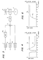
- the recording system according to the present invention differs from the conventional system in Figure 1 in that a band eliminating filter (BEF) 8a is provided between the video frequency modulator 1 and adder 3.
- Reference numerals 2 and 2a represent respective frequency modulators for the two audio signals.
- the BEF 8a has band eliminating characteristics such as shown by a curve S 1 in Figure 4. That is, the BEF 8a prevents or at least restricts passage of a frequency range from about 2 MHz to about 3 MHz, so that at least the lower of the secondary sidebands C 1 ( Figure 2) of the video signal is eliminated as shown in Figure 2b.
- the video RF signal may be distorted in either amplitude or phase or both due to the existence of the filter 8a.
- the BEF may exhibit group delay characteristics as shown by a chain line G 1 in Figure 4, which causes the deformation of the demodulated video signal.
- a notch filter as the filter 8a, or further connect a group delay compensation circuit 9a to the output of the BEF 8a as shown in Figure 5.
- the compensating circuit 9a has a constant gain S2 and group delay characteristics as shown by a chain line G 2 in Figure 6, which compensates for the group delay characteristics S1 of the BEF 8.
- FIG 7 shows another embodiment of the present invention which differs from the system in Figure 3 in that a digital encoder 10 is provided.
- the encoder 10 has an input to which the audio signal is supplied.
- An output of the encoder 10 is connected to the adder 4.
- the two audio signals supplied to the respective frequency modulators 2 and 2a are also supplied to the digital encoder 10 and digitised in a time sharing manner using a suitable modulation system such as pulse-code-modulation (PCM), to convert them into a series of pulses which are then added in the adder 4 to the outputs of modulator 2 and 2a.
- PCM pulse-code-modulation
- the eight to fourteen moedulation (EFM) system may be used.
- the frequency spectrum of the digital format includes pulses having widths of 3T to 11T when T is the bit period of the PCM signal. That is, 3T corresponds to about 720 KHz, 4T to about 540 KHz and 11T to about 200 KHz. These pulses are limited in level to about one tenth the level of the video main carrier and are added to the outputs of the filter 8a and the modulators 2 and 3a.
- the filter 8a may be a high pass filter (HPF) or a band pass filter (BPF).
- HPF high pass filter
- BPF band pass filter
- the resultant composite signal from the limiter 4 is cut around the zero crossing level and amplified to obtain a pulse-width-modulated signal.
- Figure 8 shows the frequency spectrum at the output of the adder 3 in which at the lower end is the spectrum F of the digital audio signal component.
- Figure 9 shows the waveforms at various points in the system of Figure 7, in which Figure 9a is the output waveform of the band pass filter 8a, Figure 9b is an audio output from one of the modulators 2 and 3a, Figure 9c is the waveform of the output of the digital encoder 10, Figure 9d is a composite waveform of the output of the adder 3 and Figure 9e is the pulse width modulated output of the limiter 4.
- Figure 9c the output waveform of the digital encoder 10 theoretically takes a step form as shown by the dotted line.
- the waveform in Figure 9e is obtained by cutting the waveform in Figure 9d at around the zero crossing levels and amplifying the resulting waveform, or by using a zero level comparator.
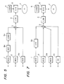
- Figure 10 is a reproducing system suitable for the recording system of Figure 3.
- the readout RF signal from a pick-up 8 is amplified by an amplifier 9 and supplied to a video band pass filter 13, an audio low pass filter 14 and a low pass filter 15.
- An output of the band pass filter 13 is supplied to a video detector 16 and demodulated thereby.
- An output of the low pass filter 14, which passes frequency components lower than 2.8 mHz is supplied to a band pass filter 17, which passes only the audio carrier, and the carrier component is detected by a detector 18.
- An output of the low pass filter 15, which passes only the digital audio information, is supplied to a decoder 19 and decoded thereby to form an audio signal.
- Figure 11 shows, in block diagram another embodiment of the reproducing system according to the present invention, which is suitable for use with the recording system of Figure 7.
- the output of the amplifier 9 is supplied to a low pass filter 15, to derive only the digital audio component F of Figure 8, and an output of the filter 15 is decoded by a decoder 19.
- the two audio signals are both FM processed and PCM processed. That is, the signal picked-up by the pick-up 8 contains the FM processed video signal, the FM processed audio signals and the PCM processed, time shared, audio signals.
- the picked-up signal is amplified by the amplifier 9 and supplied to the video band pass filter 13, the audio low pass filter 14 and the low pass filter 15, by which frequency ranges covering the secondary and higher order sidebands of the video signal are removed.
- An output of the video band pass filter 13 is demodulated by the detector 16 to provide a video output as in the embodiment of Figure 10.
- the audio signal component of the signal supplied from the amplifier 9 to the audio low pass filter 14 is passed through the latter and supplied to band pass filters 17R and 17L.
- the filter 17L is designed to pass the frequency band centered at, for example, 2.3 MHz
- the filter 17R is designed to pass the frequency band centered at 2.8 MHz. Therefore the frequency band centered at 2.3 MHz is demodulated by detector 18L to provide a L-channel audio output, and in a similar manner to the frequency band centered at 2.8 MHz is passed through the band pass filter 17R and demodulated by detector 18R to provide an R-channel audio output.
- the signal supplied to the low pass filter 15 is rejected, except for the frequency band covering the frequency spectrum F composed of the time shared PCM components shown in Figure 8. Therefore, the frequency component F is supplied to the decoder 19 and decoded separately to provide L-channel and R-channel outputs.
- the L and R channel outputs from the detectors 18L and 18R and the L and R channel outputs from the decoder 19 are selectable by means of a pair of switches 20 and 21.
- Each of the switches 20 and 21 has a pair of contacts, one contact of which is connected to the outputs of the detectors 18L and 18R, respectively, and the other contact of which is connected to the outputs of the decoder 19. Therefore, by operating the switches 20, 21, it is possible to derive L and R channel audio outputs from either the detectors 18L and 18R or the decoder 19.
Landscapes
- Engineering & Computer Science (AREA)
- Multimedia (AREA)
- Signal Processing (AREA)
- Television Signal Processing For Recording (AREA)
- Optical Recording Or Reproduction (AREA)
Applications Claiming Priority (8)
| Application Number | Priority Date | Filing Date | Title |
|---|---|---|---|
| JP149100/82 | 1982-08-30 | ||
| JP57149100A JPS5940308A (ja) | 1982-08-30 | 1982-08-30 | 記録媒体の記録方式 |
| JP15273/83 | 1983-02-03 | ||
| JP1527383U JPS59121976U (ja) | 1983-02-03 | 1983-02-03 | 多重情報記録装置 |
| JP45780/83 | 1983-03-18 | ||
| JP4578083A JPS59171011A (ja) | 1983-03-18 | 1983-03-18 | 記録再生方式 |
| JP1983119400U JPS6026604U (ja) | 1983-07-30 | 1983-07-30 | ビデオデイスク変調装置 |
| JP119400/83 | 1983-07-30 |
Publications (3)
| Publication Number | Publication Date |
|---|---|
| EP0107295A2 true EP0107295A2 (fr) | 1984-05-02 |
| EP0107295A3 EP0107295A3 (en) | 1986-08-27 |
| EP0107295B1 EP0107295B1 (fr) | 1990-08-16 |
Family
ID=27456353
Family Applications (1)
| Application Number | Title | Priority Date | Filing Date |
|---|---|---|---|
| EP19830304991 Expired EP0107295B1 (fr) | 1982-08-30 | 1983-08-30 | Système d'enregistrement et de reproduction du type vidéodisque |
Country Status (2)
| Country | Link |
|---|---|
| EP (1) | EP0107295B1 (fr) |
| DE (1) | DE3381815D1 (fr) |
Cited By (7)
| Publication number | Priority date | Publication date | Assignee | Title |
|---|---|---|---|---|
| DE3509733A1 (de) * | 1984-03-16 | 1985-10-24 | Pioneer Electronic Corp., Tokio/Tokyo | Plattenspieler mit digitalinformations-demodulationsbetrieb |
| DE3530203A1 (de) * | 1984-08-29 | 1986-03-20 | Pioneer Electronic Corp., Tokio/Tokyo | Taktsignalerzeugungsschaltung fuer ein wiedergabegeraet fuer digitalsignale |
| DE3708276A1 (de) * | 1986-03-14 | 1987-10-15 | Pioneer Electronic Corp | Bildplatte sowie aufzeichnungs- und wiedergabegeraet dafuer |
| US4855847A (en) * | 1983-12-29 | 1989-08-08 | Pioneer Electronic Corporation | Video disk reproducing device having improved motor speed control |
| EP0415289A3 (en) * | 1989-08-28 | 1991-07-31 | Sony Corporation | Cutting apparatus for an optical disc |
| EP0507525A1 (fr) * | 1991-04-03 | 1992-10-07 | Sony Corporation | Modulateurs pour signaux radio-fréquence |
| EP0984441A1 (fr) * | 1998-09-14 | 2000-03-08 | Matsushita Electric Industrial Co., Ltd. | Support d'enregistrement, appareil d'enregistrement et procédé d'enregistrement |
Family Cites Families (2)
| Publication number | Priority date | Publication date | Assignee | Title |
|---|---|---|---|---|
| FR2303426A1 (fr) * | 1975-03-04 | 1976-10-01 | Thomson Brandt | Procede de protection contre les evanouissements profonds des canaux de transmission, enregistrements et appareils suivant ce procede |
| DE3110968A1 (de) * | 1981-03-20 | 1982-09-30 | Licentia Patent-Verwaltungs-Gmbh, 6000 Frankfurt | Videorecorder zur aufzeichnung eines mit dem videosignal frequenzmodulierten bildtraegers |
-
1983
- 1983-08-30 EP EP19830304991 patent/EP0107295B1/fr not_active Expired
- 1983-08-30 DE DE8383304991T patent/DE3381815D1/de not_active Expired - Lifetime
Cited By (16)
| Publication number | Priority date | Publication date | Assignee | Title |
|---|---|---|---|---|
| US4855847A (en) * | 1983-12-29 | 1989-08-08 | Pioneer Electronic Corporation | Video disk reproducing device having improved motor speed control |
| DE3509733A1 (de) * | 1984-03-16 | 1985-10-24 | Pioneer Electronic Corp., Tokio/Tokyo | Plattenspieler mit digitalinformations-demodulationsbetrieb |
| DE3530203A1 (de) * | 1984-08-29 | 1986-03-20 | Pioneer Electronic Corp., Tokio/Tokyo | Taktsignalerzeugungsschaltung fuer ein wiedergabegeraet fuer digitalsignale |
| DE3708276A1 (de) * | 1986-03-14 | 1987-10-15 | Pioneer Electronic Corp | Bildplatte sowie aufzeichnungs- und wiedergabegeraet dafuer |
| US4782402A (en) * | 1986-03-14 | 1988-11-01 | Pioneer Electronic Corporation | Video disk with multiplexed video and digital information |
| EP0626680A3 (fr) * | 1989-08-28 | 1997-11-19 | Sony Corporation | Appareil pour la gravure d'un disque optique |
| US5084856A (en) * | 1989-08-28 | 1992-01-28 | Sony Corporation | Cutting apparatus for an optical disc |
| EP0415289A3 (en) * | 1989-08-28 | 1991-07-31 | Sony Corporation | Cutting apparatus for an optical disc |
| EP0507525A1 (fr) * | 1991-04-03 | 1992-10-07 | Sony Corporation | Modulateurs pour signaux radio-fréquence |
| KR100262790B1 (ko) * | 1991-04-03 | 2000-08-01 | 이데이 노부유끼 | 무선 주파수 변조기 |
| EP0984441A1 (fr) * | 1998-09-14 | 2000-03-08 | Matsushita Electric Industrial Co., Ltd. | Support d'enregistrement, appareil d'enregistrement et procédé d'enregistrement |
| EP0987698A1 (fr) * | 1998-09-14 | 2000-03-22 | Matsushita Electric Industrial Co., Ltd. | Support d'enregistrement, appareil d'enregistrement et procédé d'enregistrement |
| WO2000016323A1 (fr) * | 1998-09-14 | 2000-03-23 | Matsushita Electric Industrial Co., Ltd. | Support d'enregistrement, appareil pour l'enregistrement et procede d'enregistrement |
| US6157609A (en) * | 1998-09-14 | 2000-12-05 | Matsushita Electric Industrial Co., Ltd. | Recording medium, recording apparatus and recording method |
| US6349081B1 (en) | 1998-09-14 | 2002-02-19 | Matsushita Electric Industrial Co., Ltd. | Recording medium, recording apparatus and recording method |
| US6359846B1 (en) | 1998-09-14 | 2002-03-19 | Matsushita Electric Industrial Co., Ltd. | Recording medium recording apparatus and recording method |
Also Published As
| Publication number | Publication date |
|---|---|
| EP0107295A3 (en) | 1986-08-27 |
| DE3381815D1 (de) | 1990-09-20 |
| EP0107295B1 (fr) | 1990-08-16 |
Similar Documents
| Publication | Publication Date | Title |
|---|---|---|
| US4908581A (en) | Frequency demodulator having circuit cancelling undesired signal components | |
| US4322746A (en) | Crosstalk attenuator system | |
| US4464684A (en) | Video recorder providing transient-free audio signals | |
| EP0107295A2 (fr) | Système d'enregistrement et de reproduction du type vidéodisque | |
| KR920003521B1 (ko) | 자기기록장치 및 자기기록 재생장치 | |
| US4683502A (en) | Video disc type recording and reproducing system with interference reduction filter | |
| EP0086496B1 (fr) | Appareil magnétique d'enregistrement et de reproduction | |
| US4384302A (en) | Composite video signal limiter | |
| JPH0832069B2 (ja) | 記録情報再生装置 | |
| US4691246A (en) | Apparatus for multiplex recording and reproduction of audio and video signals | |
| US5053882A (en) | Video signal optical transmission system | |
| KR940009486B1 (ko) | 주파수변조파의 기록장치 | |
| EP0363965B1 (fr) | Procédé d'enregistrement d'un signal vidéo couleur fin sur un milieu d'enregistrement optique et procédé de reproduction d'un tel signal vidéo couleur enregistré | |
| US5231542A (en) | Method and device for improving bass response in magnetic tape recording | |
| JPS6252994B2 (fr) | ||
| JPS6120068B2 (fr) | ||
| JPS6214906B2 (fr) | ||
| JPS6049987B2 (ja) | Fm復調回路 | |
| US4864427A (en) | Disk reproducing method and apparatus for disks with different video bandwidths | |
| JPH0411424Y2 (fr) | ||
| EP0300801A2 (fr) | Appareil de démodulation de fréquence | |
| EP0434356B1 (fr) | Enregistreur à bande vidéo | |
| CA1078063A (fr) | Circuit reducteur des bruits | |
| EP0082205B1 (fr) | Circuit de reproduction d'un signal sonore multiplexe de television | |
| US3869583A (en) | Quadruphonic disc recording system utilizing single sideband modulation |
Legal Events
| Date | Code | Title | Description |
|---|---|---|---|
| PUAI | Public reference made under article 153(3) epc to a published international application that has entered the european phase |
Free format text: ORIGINAL CODE: 0009012 |
|
| AK | Designated contracting states |
Designated state(s): DE GB NL |
|
| PUAL | Search report despatched |
Free format text: ORIGINAL CODE: 0009013 |
|
| AK | Designated contracting states |
Kind code of ref document: A3 Designated state(s): DE GB NL |
|
| 17P | Request for examination filed |
Effective date: 19870219 |
|
| 17Q | First examination report despatched |
Effective date: 19881222 |
|
| GRAA | (expected) grant |
Free format text: ORIGINAL CODE: 0009210 |
|
| AK | Designated contracting states |
Kind code of ref document: B1 Designated state(s): DE GB NL |
|
| REF | Corresponds to: |
Ref document number: 3381815 Country of ref document: DE Date of ref document: 19900920 |
|
| PLBE | No opposition filed within time limit |
Free format text: ORIGINAL CODE: 0009261 |
|
| STAA | Information on the status of an ep patent application or granted ep patent |
Free format text: STATUS: NO OPPOSITION FILED WITHIN TIME LIMIT |
|
| REG | Reference to a national code |
Ref country code: GB Ref legal event code: 746 |
|
| 26N | No opposition filed | ||
| PGFP | Annual fee paid to national office [announced via postgrant information from national office to epo] |
Ref country code: GB Payment date: 19940822 Year of fee payment: 12 |
|
| PGFP | Annual fee paid to national office [announced via postgrant information from national office to epo] |
Ref country code: DE Payment date: 19940823 Year of fee payment: 12 |
|
| PGFP | Annual fee paid to national office [announced via postgrant information from national office to epo] |
Ref country code: NL Payment date: 19940831 Year of fee payment: 12 |
|
| PG25 | Lapsed in a contracting state [announced via postgrant information from national office to epo] |
Ref country code: GB Effective date: 19950830 |
|
| PG25 | Lapsed in a contracting state [announced via postgrant information from national office to epo] |
Ref country code: NL Effective date: 19960301 |
|
| GBPC | Gb: european patent ceased through non-payment of renewal fee |
Effective date: 19950830 |
|
| NLV4 | Nl: lapsed or anulled due to non-payment of the annual fee |
Effective date: 19960301 |
|
| PG25 | Lapsed in a contracting state [announced via postgrant information from national office to epo] |
Ref country code: DE Effective date: 19960501 |