EP0107429A2 - Machine pour la fermeture de récipients - Google Patents
Machine pour la fermeture de récipients Download PDFInfo
- Publication number
- EP0107429A2 EP0107429A2 EP83306092A EP83306092A EP0107429A2 EP 0107429 A2 EP0107429 A2 EP 0107429A2 EP 83306092 A EP83306092 A EP 83306092A EP 83306092 A EP83306092 A EP 83306092A EP 0107429 A2 EP0107429 A2 EP 0107429A2
- Authority
- EP
- European Patent Office
- Prior art keywords
- pick
- cap
- container
- caps
- members
- Prior art date
- Legal status (The legal status is an assumption and is not a legal conclusion. Google has not performed a legal analysis and makes no representation as to the accuracy of the status listed.)
- Withdrawn
Links
Images


Classifications
-
- B—PERFORMING OPERATIONS; TRANSPORTING
- B67—OPENING, CLOSING OR CLEANING BOTTLES, JARS OR SIMILAR CONTAINERS; LIQUID HANDLING
- B67B—APPLYING CLOSURE MEMBERS TO BOTTLES JARS, OR SIMILAR CONTAINERS; OPENING CLOSED CONTAINERS
- B67B3/00—Closing bottles, jars or similar containers by applying caps
- B67B3/20—Closing bottles, jars or similar containers by applying caps by applying and rotating preformed threaded caps
- B67B3/2013—Closing bottles, jars or similar containers by applying caps by applying and rotating preformed threaded caps by carousel-type capping machines
- B67B3/2033—Closing bottles, jars or similar containers by applying caps by applying and rotating preformed threaded caps by carousel-type capping machines comprising carousel co-rotating capping heads
Definitions
- the present invention relates to the application of closure caps to containers having externally screw-threaded necks.
- the containers are travelling continuously or by indexed steps when passing under the feed chute.
- the containers may be moving in an arcuate path in a star wheel or may be travelling on a linearly moving conveyor.
- the leading blank in the feed chute projects from the feed end of the chute and the chute is somewhat inclined to the direction in which the containers travel so that the top end of the bottle neck just strikes the inside of the closure blank skirt and draws the blank out of the chute, while passing under a hold-down plate which is progressively curved to an essentially horizontal position beyond the exit end of the chute. That arrangement works satisfactorily for feeding unthreaded blanks, since the internal diameter of the closure skirt is greater than the diameter of the bottle neck over the threads.
- the overhead pick-up member is preferably rotated to effect the initial turning of the cap.
- the cap itself may be directly driven, for example by contact with a stationary friction or toothed member or rotating wheel.
- the overhead pick-up'member is preferably carried in a horizontal circular path by a turret.
- the pick-up member is preferably a vacuum pad, carried on the lower end of a shaft, which is slidably mounted for vertical movement in the turret, and also arranged for rotation in the turret, which is itself arranged co-axially with a star-wheel for driving the bottles.
- the rotation of the pick-up member is preferably achieved by engagement of a drive wheel on its upper end with a stationary arcuate friction plate or toothed plate.
- the cap may itself be turned by engagement with the friction plate. In such case the cap may itself be turned in relation to the vacuum pad.
- the vacuum pad is preferably arranged to pick up a cap which has been fed from a cap feed chute and to remain engaged with the cap until the container reaches a point where it is released from the co-axial starwheel for transfer to a second starwheel which carries it forward possibly under a spinning head for final tightening.
- the cap pick-up member is preferably supported at a controlled level throughout its path, except in that portion of its path where the cap is in place on the container. In that portion of its path the cap pick-up member is preferably left floating so that it may follow the cap downwardly as it is screwed onto the container thread.
- suction may be applied through the pick-up member throughout its orbital path, suction may be switched off from the pick-up member at a point where the prescrewing is completed, so as to release the cap completely from the pick-up member at or before the point where transfer to a second starwheel or discharge means takes place.
- the pick-up head turret 1 shown in Figures 2 and 3, is supported by and driven by a co-axial starwheel 2, shown in Figure 3.
- Bottles or other containers are delivered sequentially to starwheel 2 in conventional manner by a bottle feed conveyor 3 or other conventional bottle feed.
- the bottles are transferred sequentially from starwheel 2 to a starwheel 4, which is co-axial and synchronised with a turret (not shown) carrying the spinning heads 5, by which the caps are to be tightened on the bottles.
- Prethreaded caps are fed to the turret 1 by means of a cap feed chute 6 ( Figure 2), which is preferably interlinked with a detector (not shoown) inspecting the bottle feed conveyor to detect a gap in the supply of bottles. In the event of such a gap the supply of caps to the turret 1 is interrupted.
- the cap feed chute 6 is connected to a stationary horizontal plate 7 and arcuate guide plate 8.
- the caps are picked up sequentially from the feed chute 6 by a star wheel 9, forming part of the turret 1, and are progressed sequentially along the plate 7, in which they are held at a defined position in relation to the central axis of the turret by the co-operation of the shape of the individual, cup-receiving recesses 10 in starwheel 9 in co-operation with the arcuate guide plate 8.
- a suction pick-up head 11 descends onto the cap, so that on reaching the end of plate 7 the cap is supported on the lower face of the pick-up head 11 in an essentially horizontal position.
- Each pick-up head 11 is carried by a support bracket 12, which is mounted for vertical movement on a pair of guide posts 14.
- the guide posts 14 are mounted at equiangular positions on the starwheel 9.
- Each bracket 12 is provided with a cam roller 15, which follows a stationary cam track 16 to effect vertical movement of the associated bracket 12 during rotation of starwheel 9 about the axis of a stationary spindle 17.
- the cam track is non-continuous as earlier explained and a gap is formed at 18 to allow the bracket 12 to descend freely while it is turned through about 90i about the axis of the spindle 17.
- the spindle 17 has an axial suction passage 19, which communicates with a part-circular peripheral gallery 20 lying within a hub member 21, secured to starwheel 9.
- the hub member 21 is provided with radial suction passages 22, in each of which a flexible hose 23 is mounted for connection with a suction passage 24 in a pick-up head support bracket 12.
- Each pick-up head 11 is carried by a hollow spindle 25, mounted in a bush 26 in a bracket 12 and carrying a friction drive wheel 27 at its upper end.
- the spindle 25 has a peripheral gallery 28 leading into the axial passage 29 of the spindle and communicating with the suction passage 24 in bracket 12.
- suction is applied at the lower face of the pick-up head during that part of each cycle where the associated suction passage 22 registers with the part circular gallery 20, irrespective of the:vertical movement of the bracket 12 and rotation of the spindle 25.
- FIG 1 A development of the cam track 16 is shown in Figure 1 and its relationship with the suction gallery 20 is shown in Figure 2.
- the pick-up head 11 is clear of the top of the cap.
- head 11 descends onto the cap and at station B the associated suction passage 22 comes into register with gallery 20 to switch on the suction to pick up the cap, so that at the end of the plate 7 the cap is supported beneath the suction pick-up head 11.
- the pick-up head descends onto the bottle and the cam roller 15 leaves the cam track 16.
- the friction wheel 27 comes into contact with a stationary arcuate friction plate 30. As the wheel 27 rolls along the friction plate 30, the spindle 25 and pick-up head 11 turn to run the cap down the neck thread of the underlying container driven by starwheel 2.
- the cam track 16 picks up the cam roller 15 at station E.
- the associated suction passage 22 reaches the end of gallery 20 before reaching station F, at which the container is transferred to the starwheel 4. Since suction has been switched off before reaching station F , the cap is free to move laterally in relation to the pick-up head 11 at this point.
- the essential feature of this sequence of operations is the maintenance of the cap in a level position by the pick-up head as it is carried from the feed chute, lowered onto the container neck and pre-screwed onto the container neck.
- the caps may be sufficiently tightened by the rotation imparted by engagement of the wheel 27 with the friction plate 30.
- starwheel 4 acts only as a means for discharging the containers from starwheel 2 and the associated spinning heads may be omitted.
- Starwheel 4 may be replaced by other discharge means.
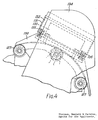
- toothed wheels 127 are mounted on the spindles 25 for co-operation with and engagement by an arcuate toothed rack 130.
- the rack 130 has a tail 131 slidably mounted in a fixed support 132, which is supported by a bracket 133 carried by an overhead structure 134.
- the rack 130 is pressed outwardly against the toothed wheels by a pair of compression springs 135, which allow the rack 130 to yield in the event of mismatch,between the teeth on wheels 127 and the teeth on rack 130. It will be understood that the teeth on both members are very shallow and of small angular extent.
- the application of suction to the pick-up heads 11 may be continued throughout the cycle or at least until the region of station F. At that location any unapplied cap may be removed from the pick-up head either by interruption of the suction to the pick-up head or by means of a mechanical knock-off ,device, (not shown), which physically separates an unapplied cap from the pick-up head.
- the rotation of the closure caps in the tightening direction may be achieved by rotating the cap or the pick-up head by means of a drive belt or the like in place of the stationary friction plate 30.
Landscapes
- Engineering & Computer Science (AREA)
- Mechanical Engineering (AREA)
- Sealing Of Jars (AREA)
- Specific Conveyance Elements (AREA)
- Closing Of Containers (AREA)
Applications Claiming Priority (2)
| Application Number | Priority Date | Filing Date | Title |
|---|---|---|---|
| GB8229676 | 1982-10-18 | ||
| GB8229676 | 1982-10-18 |
Publications (2)
| Publication Number | Publication Date |
|---|---|
| EP0107429A2 true EP0107429A2 (fr) | 1984-05-02 |
| EP0107429A3 EP0107429A3 (en) | 1985-03-13 |
Family
ID=10533667
Family Applications (1)
| Application Number | Title | Priority Date | Filing Date |
|---|---|---|---|
| EP83306092A Withdrawn EP0107429A3 (en) | 1982-10-18 | 1983-10-07 | Improvements in capping machines for containers |
Country Status (6)
| Country | Link |
|---|---|
| US (1) | US4559759A (fr) |
| EP (1) | EP0107429A3 (fr) |
| JP (1) | JPS5993686A (fr) |
| AU (1) | AU2019183A (fr) |
| ES (1) | ES8406370A1 (fr) |
| ZA (1) | ZA837649B (fr) |
Cited By (3)
| Publication number | Priority date | Publication date | Assignee | Title |
|---|---|---|---|---|
| ITBO20080777A1 (it) * | 2008-12-23 | 2010-06-24 | Moussavi Alireza Ditta Individuale | Macchina per il dosaggio di fluidi in contenitori |
| EP2724975A1 (fr) * | 2012-10-23 | 2014-04-30 | Krones AG | Dispositif et procédé d'alimentation de bouchons |
| CN112456410A (zh) * | 2020-11-02 | 2021-03-09 | 徐景峰 | 一种可升降可定位夹紧的小型封罐机 |
Families Citing this family (14)
| Publication number | Priority date | Publication date | Assignee | Title |
|---|---|---|---|---|
| JPH01144397U (fr) * | 1988-03-28 | 1989-10-04 | ||
| IT1234085B (it) * | 1989-05-25 | 1992-04-29 | Azionaria Costruzioni Acma Spa | Apparecchiatura per posizionare in maniera corretta degli erogatori daapplicare a dei contenitori |
| DE3927911A1 (de) * | 1989-08-24 | 1991-02-28 | Alfill Getraenketechnik | Verfahren und vorrichtung zum fuellen und verschliessen von dosen |
| IT1242601B (it) * | 1990-10-31 | 1994-05-16 | Azionaria Costruzioni Acma Spa | Apparecchiatura per l'applicazione di tappi a contenitori. |
| DE4136464A1 (de) * | 1991-11-06 | 1993-05-13 | Seitz Enzinger Noll Masch | Vorrichtung zum vereinzeln und bereitstellen von kronenkorken oder dgl. verschluessen |
| WO1993016952A1 (fr) * | 1992-02-26 | 1993-09-02 | Amcor Limited | Appareil pour amener des capsules en plastique a une machine a capsuler |
| ITBO20040325A1 (it) * | 2004-05-20 | 2004-08-20 | Tognazzi Srl | Dispositivo per l'avvitamento di tappi su corrispondenti articoli |
| KR100652408B1 (ko) * | 2005-04-27 | 2006-12-01 | 삼성전자주식회사 | 베이어 패턴의 디지털 컬러 영상 신호를 처리하는 방법 및장치 |
| WO2007054985A1 (fr) * | 2005-11-11 | 2007-05-18 | Tecnomax-Due S.N.C. Di Novarini S. & Boccardi M. | Tête de vissage/roulement pour bouchons pré-filetés |
| US7836669B1 (en) * | 2006-03-09 | 2010-11-23 | The Sherwin Williams Company | Lid applying apparatus and method with lid orienting device |
| US7603828B2 (en) * | 2006-04-26 | 2009-10-20 | Alcoa Closure Systems International, Inc. | Track adjustable mounting assemblies and associated methods |
| US7481122B2 (en) | 2006-10-20 | 2009-01-27 | Vibrac Llc | Apparatus for measuring torque |
| WO2010126928A2 (fr) * | 2009-05-01 | 2010-11-04 | Michelli Richard D | Appareil et procédés de remplissage/encapsulation de bouteille portable et automatique |
| DE102012103518A1 (de) * | 2012-04-20 | 2013-10-24 | Krones Ag | Vorrichtung zum Verschließen von Behältern |
Family Cites Families (11)
| Publication number | Priority date | Publication date | Assignee | Title |
|---|---|---|---|---|
| US1748961A (en) * | 1928-04-25 | 1930-03-04 | U S Bottlers Machinery Company | Capping appliance |
| US1888470A (en) * | 1931-08-17 | 1932-11-22 | Arthur I Risser | Screw cap applying machine |
| US2082048A (en) * | 1933-08-11 | 1937-06-01 | Pneumatic Scale Corp | Closure applying machine |
| US2310868A (en) * | 1940-07-17 | 1943-02-09 | Oswego Falls Corp | Machine for applying hood caps |
| FR1073442A (fr) * | 1952-12-18 | 1954-09-24 | Pneumatic Scale Corp | Appareil pour la pose de fermetures à vis sur des récipients |
| GB814585A (en) * | 1956-09-06 | 1959-06-10 | Owens Illinois Glass Co | Improvements in or relating to container closing apparatus |
| US2876606A (en) * | 1957-08-19 | 1959-03-10 | Owens Illinois Glass Co | Container closing apparatus |
| US3184897A (en) * | 1962-10-08 | 1965-05-25 | Anchor Hocking Glass Corp | Container pressure device |
| US3380225A (en) * | 1965-10-12 | 1968-04-30 | Anchor Hocking Glass Corp | Cap applicator |
| US3852941A (en) * | 1973-08-20 | 1974-12-10 | Pennwalt Corp | Vial capping apparatus |
| US4308707A (en) * | 1979-12-03 | 1982-01-05 | Owens-Illinois, Inc. | Closure pre-tightener for closure applicating machines |
-
1983
- 1983-10-07 EP EP83306092A patent/EP0107429A3/en not_active Withdrawn
- 1983-10-13 US US06/541,535 patent/US4559759A/en not_active Expired - Fee Related
- 1983-10-14 ZA ZA837649A patent/ZA837649B/xx unknown
- 1983-10-14 AU AU20191/83A patent/AU2019183A/en not_active Abandoned
- 1983-10-17 ES ES526525A patent/ES8406370A1/es not_active Expired
- 1983-10-18 JP JP58195125A patent/JPS5993686A/ja active Pending
Cited By (4)
| Publication number | Priority date | Publication date | Assignee | Title |
|---|---|---|---|---|
| ITBO20080777A1 (it) * | 2008-12-23 | 2010-06-24 | Moussavi Alireza Ditta Individuale | Macchina per il dosaggio di fluidi in contenitori |
| WO2010073118A1 (fr) * | 2008-12-23 | 2010-07-01 | Moussavi Alireza Ditta Individuale | Machine pour doser des fluides dans des récipients |
| EP2724975A1 (fr) * | 2012-10-23 | 2014-04-30 | Krones AG | Dispositif et procédé d'alimentation de bouchons |
| CN112456410A (zh) * | 2020-11-02 | 2021-03-09 | 徐景峰 | 一种可升降可定位夹紧的小型封罐机 |
Also Published As
| Publication number | Publication date |
|---|---|
| AU2019183A (en) | 1984-05-03 |
| ZA837649B (en) | 1984-07-25 |
| JPS5993686A (ja) | 1984-05-30 |
| EP0107429A3 (en) | 1985-03-13 |
| US4559759A (en) | 1985-12-24 |
| ES526525A0 (es) | 1984-08-01 |
| ES8406370A1 (es) | 1984-08-01 |
Similar Documents
| Publication | Publication Date | Title |
|---|---|---|
| US4559759A (en) | Capping machines for containers | |
| EP0014173B1 (fr) | Machine à capsuler | |
| US4205502A (en) | Rotary bottle closing machine | |
| US4624098A (en) | Container restraint system | |
| US6115992A (en) | Apparatus and method for pre-capping containers | |
| US3714760A (en) | High speed rotary container sealing machine with inclined sealing heads | |
| US4663913A (en) | Closure application system | |
| US9090408B2 (en) | Apparatus and method of conveying containers with base guidance | |
| US5284001A (en) | Spindle type straight line capper | |
| US2829757A (en) | Container feeding mechanisms | |
| US3537231A (en) | Bottle capper | |
| US20040065525A1 (en) | Transfer unit for containers | |
| US2810249A (en) | Apparatus for directing applicators into bottles | |
| US3782542A (en) | Automatic bottle thread inspection apparatus | |
| US5373683A (en) | Process and device for filling and sealing of containers | |
| US5012630A (en) | Closure application system | |
| US6430896B1 (en) | Capping machine | |
| US3309838A (en) | Capping machine | |
| US6345713B1 (en) | Automatic machine for overturning containers and the like | |
| US4724035A (en) | Apparatus for applying base cups to bottles | |
| WO2022214933A1 (fr) | Machine en ligne de remplissage et de capsulage de récipients | |
| US3073090A (en) | Means for sealing threaded-type containers | |
| US4070854A (en) | Apparatus for removing bottle caps | |
| US5050722A (en) | Apparatus for orienting articles | |
| US2801650A (en) | Filling structure |
Legal Events
| Date | Code | Title | Description |
|---|---|---|---|
| PUAI | Public reference made under article 153(3) epc to a published international application that has entered the european phase |
Free format text: ORIGINAL CODE: 0009012 |
|
| AK | Designated contracting states |
Designated state(s): AT BE CH DE FR GB IT LI NL SE |
|
| PUAL | Search report despatched |
Free format text: ORIGINAL CODE: 0009013 |
|
| AK | Designated contracting states |
Designated state(s): AT BE CH DE FR GB IT LI NL SE |
|
| 17P | Request for examination filed |
Effective date: 19850906 |
|
| 17Q | First examination report despatched |
Effective date: 19860324 |
|
| STAA | Information on the status of an ep patent application or granted ep patent |
Free format text: STATUS: THE APPLICATION HAS BEEN WITHDRAWN |
|
| 18W | Application withdrawn |
Withdrawal date: 19860902 |
|
| RIN1 | Information on inventor provided before grant (corrected) |
Inventor name: HERBERT, JAMES FREDERICK |