EP0107737A1 - Drahtschneidelektrode für funkenerosive drahtschneidmaschine - Google Patents
Drahtschneidelektrode für funkenerosive drahtschneidmaschine Download PDFInfo
- Publication number
- EP0107737A1 EP0107737A1 EP83901393A EP83901393A EP0107737A1 EP 0107737 A1 EP0107737 A1 EP 0107737A1 EP 83901393 A EP83901393 A EP 83901393A EP 83901393 A EP83901393 A EP 83901393A EP 0107737 A1 EP0107737 A1 EP 0107737A1
- Authority
- EP
- European Patent Office
- Prior art keywords
- wire electrode
- wire
- cut
- electrode
- cutting apparatus
- Prior art date
- Legal status (The legal status is an assumption and is not a legal conclusion. Google has not performed a legal analysis and makes no representation as to the accuracy of the status listed.)
- Granted
Links
- 238000003754 machining Methods 0.000 title abstract 2
- 238000005520 cutting process Methods 0.000 claims description 59
- 239000003990 capacitor Substances 0.000 claims description 14
- 230000005611 electricity Effects 0.000 claims description 6
- 238000007599 discharging Methods 0.000 claims description 2
- 238000010438 heat treatment Methods 0.000 abstract description 9
- 230000000704 physical effect Effects 0.000 abstract description 2
- 238000009760 electrical discharge machining Methods 0.000 description 14
- 238000001816 cooling Methods 0.000 description 7
- 239000012530 fluid Substances 0.000 description 5
- 230000007246 mechanism Effects 0.000 description 5
- 238000010586 diagram Methods 0.000 description 3
- 238000005516 engineering process Methods 0.000 description 3
- 238000000034 method Methods 0.000 description 3
- 230000002093 peripheral effect Effects 0.000 description 3
- 229910001369 Brass Inorganic materials 0.000 description 2
- XEEYBQQBJWHFJM-UHFFFAOYSA-N Iron Chemical group [Fe] XEEYBQQBJWHFJM-UHFFFAOYSA-N 0.000 description 2
- 239000010951 brass Substances 0.000 description 2
- 239000012811 non-conductive material Substances 0.000 description 2
- 235000008733 Citrus aurantifolia Nutrition 0.000 description 1
- 235000011941 Tilia x europaea Nutrition 0.000 description 1
- 229910001297 Zn alloy Inorganic materials 0.000 description 1
- 238000005452 bending Methods 0.000 description 1
- 239000004020 conductor Substances 0.000 description 1
- 238000010276 construction Methods 0.000 description 1
- TVZPLCNGKSPOJA-UHFFFAOYSA-N copper zinc Chemical compound [Cu].[Zn] TVZPLCNGKSPOJA-UHFFFAOYSA-N 0.000 description 1
- 238000004880 explosion Methods 0.000 description 1
- 230000004927 fusion Effects 0.000 description 1
- 239000004571 lime Substances 0.000 description 1
- 239000000463 material Substances 0.000 description 1
- 239000002184 metal Substances 0.000 description 1
- 229910052751 metal Inorganic materials 0.000 description 1
- 238000012986 modification Methods 0.000 description 1
- 230000004048 modification Effects 0.000 description 1
- 238000013021 overheating Methods 0.000 description 1
- 230000035939 shock Effects 0.000 description 1
- 238000005482 strain hardening Methods 0.000 description 1
- 230000008016 vaporization Effects 0.000 description 1
Images

Classifications
-
- B—PERFORMING OPERATIONS; TRANSPORTING
- B23—MACHINE TOOLS; METAL-WORKING NOT OTHERWISE PROVIDED FOR
- B23H—WORKING OF METAL BY THE ACTION OF A HIGH CONCENTRATION OF ELECTRIC CURRENT ON A WORKPIECE USING AN ELECTRODE WHICH TAKES THE PLACE OF A TOOL; SUCH WORKING COMBINED WITH OTHER FORMS OF WORKING OF METAL
- B23H7/00—Processes or apparatus applicable to both electrical discharge machining and electrochemical machining
- B23H7/02—Wire-cutting
- B23H7/08—Wire electrodes
- B23H7/10—Supporting, winding or electrical connection of wire-electrode
Definitions
- This invention relates to a wire-electrode cutting apparatus and, more particularly, to a wire-electrode cutting apparatus to cut a wire-cutting electrode to be used for a wire-cut electric discharge machine.
- a wire-electrode to be used for the wire-cut spark erosion has a tendency such that the spark erosion is performed by setting the tensile strength of the wire-electrode to be a higher value upon working using a wire having a high-tensile strength, e.g. a brass (Copper-Zinc alloy) or the like as an electrode wire.
- a wire having a high-tensile strength e.g. a brass (Copper-Zinc alloy) or the like as an electrode wire.
- pliers cutting nipper, cutting pliers, or other various kinds of metal scissors to cut the wire electrode.
- the cutting by means of such various kinds of tools and the like causes various types of burr, bending portion, damaged portion, etc. at the cutting edge portion by the wire-electrode.
- a diameter of its cutting surface is substantially the same as that of the wire-electrode used, or the cutting surface is pressed flat-like shape having a large maximum diameter.
- the cutting portion upon the cutting of a wire-electrode, the cutting portion is pulled and stretched so as to be thin by applying a tensile force to the wire electrode to cut the wire while causing the work hardening, thereby obtaining the cutting portion which has a better linearity but no burr.
- a wire-electrode with a high tensile strength that has been frequently used in recent years as described above, even if it is cut by means of a mechanical stretching-cutting apparatus, the electrode wire will have been cut before it is sufficiently pulled and stretched since an elongation percentage is low, although the tensile strength is high, thus cutting edge portion does not become the straight line.
- the electrode wire is cut so that the cross section of the cutting portion is about the same shape before cutting, and any burrs and the like are frequently formed on the cutting surface. Hence, it is difficult to pass the wire-electrode through the guides and nozzles of the working machine, 'the inserting hole of the workpiece or the like.
- the present invention was made to eliminate such conventional drawbacks. It is and object of the invention to provide a novel wire cutting apparatus in which a simple heating apparatus can be used and the wire electrode can be almost instantaneously cut at a desired location, and in which the wire electrode can be cut so that the end portion is straight and elongated and in a better state such that no burr exists at the cutting surface.
- the gist of the present invention is that the wire electrode cutting apparatus is constituted in such a manner that the cutting is done while pulling and stretching and locally heating the wire electrode at a constant temperature in the state that a constant tensile force is applied to the cutting portion of the wire electrode, thereby obtaining the elongated cutting edge without any burrs.
- a wire electrode cutting apparatus 10 comprises a wire electrode sending section 1 and a wire electrode pulling section 2 which are mounted on bases or the like (not shown) attached respectively to a pair of upper and lower arms (not shown) that are fixedly or elevationally supported to a column of a wire-cut electric discharge machine.
- the sending section 1 and the pulling section 2 are similarly constituted; namely, they comprise capstans 11 and 21, pinch rollers 12 and 22 adapted to pressure a wire electrode 3 to the capstans 11 and 21, and motors 13 and 23 for driving the capstans 11 and 21.
- a reference numeral 4 is a reel for supplying the wire electrode 3, while 5 collecting reel therefor.
- the wire electrode 3 is pulled out from the supplying reel 4 and gets through the pass between the capstan 11 and the pinch roller 12. Then, it gets through the pass between the capstan 21 and the pinch roller 22 at the wire electrode pulling section 2 and is rolled round collecting reel 5.
- the wire electrode 3 may be cut so as to be a proper length and may be thrown into a vessel and the like as short pieces.
- the pinch rollers 12 and 22 are constituted in such a manner that they sufficiently and strongly press the wire electrode 3 to the capstans 11 and 21 by well-known means such as a spring or the like, and these pinch rollers are rotatably supported while being applied the frictional forces by the capstans 11 and 21.
- the motor 13 is not necessarily an essential component for the spark erosion, it is needed for automatic wire- threading after cutting the wire electrode.
- the capstan 21 is coupled to the motor 23 and is constituted so as to rotate in the direction so that the wire electrode 3 moves from the sending portion 1 to the pulling section 2 and so as not to move the wire electrode 3 if the motor 23 is inoperative during the spark erosion.
- the peripheral speed of the capstan 21 on the pulling side is larger than that of the capstan 11 on the sending slide because the diameter of the capstan 11 has been present to be slightly smaller than that of the capstan 12; thus, a predetermined tensile force is applied to the wire electrode 3.
- the motor 13 to drive the capstan 11 may be used as a braking generator, and the capstan 11 may be also used not as a capstan but as a braking roller or a loading roller.
- a capacitor 83 is charged to a predetermined voltage through a resistor 81 by a DC power supply (not shown) connected to terminals 82. and 84.
- Power feeding pulleys 6 and 7 are arranged with a predetermined interval between the sending the sending section 1 and the pulling section 2. These power feeding pulleys 6 and 7 are adapted to detachably about on the wire electrode 3 and are connected through a switch 8 with the capacitor 83. These pulleys are come into contact with the wire electrode 3 that will be stretched between the sending section 1 and the pulling section 2 if necessary when the wire electrode is cut.
- the switch 8 When the switch 8 is turned on, the electricity accumulated in the capacitor 83 flows from the power feeding pulley 6 through the wire electrode 3 between the pulleys 6 and 7 to the pulley 7, thereby heating the wire electrode 3.
- well-known wire electrode positioning guides of the die type or boat form having a V groove or the lime are respectively provided between the sending section 1 and the power feeding pulley 6 and between the pulling section 2 and the power feeding pulley 7.
- the portion between the above-mentioned pair of positioning guides is a workpiece working section.
- a tension detecting mechanism 9 for detecting a tensile force to be applied to the wire electrode 3 is attached to the motor 23 connected to the capstan 21 of the pulling section 2.
- the tension detecting mechanism 9 comprises a power supply 91 for supplying a driving power to the motor 23, a resistor 92 interposed between the motor 23 and the power supply 91 for sensing the power supplied, and a signal converter 93. Input terminals of the signal converter 93 are connected across the resistor 92 and its output terminal is connected to the switch 8 to sending a switching control signal.
- the capstans 11 and 21 of the sending section 1 and pulling section 2 are rotated at the same speed or with a slight difference in speed, and the wire electrode 3 which has been wound around the supplying reel 4 is sent out from the sending section 1 to the pulling section 2.
- the power feeding pulleys 6 and 7 are first moved to come into contact with the wire electrode 3, then the rotation of the motor 13 of the sending section 1 is stopped and only the motor 23 of the pulling section 2 is rotated.
- the wire electrode 3 is fixed on the side of sending section 1 or forcibly pulled for causing the motor 13 or the like to reversely rotate, so that the tensile force to be applied to the wire electrode 3 rapidly increases.
- the wire electrode 3 is constituted in such a manner that it is sandwiched by the capstan 11 and pinch roller 12 and by the capstan 21 and pinch roller 22, this may be constituted in such a manner as shown in Fig. 2 that the wire electrode 3 is wrapped around the capstan 11 and pinch roller 12 and then around the capstan 21 and pinch roller 22 (this wrapping order may by vice versa; namely, the wire electrode 3 may be wrapped around the pinch roller 12 and capstan 11 and then around the pinch roller 22 and capstan 21) in order to prevent the wire electrode 3 from slipping.
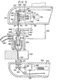
- FIG. 3 there is illustrated the state in that a wire electrode cutting apparatus with a construction similar to the above-mentioned embodiment is installed in the electric discharge machine.
- reference numerals 101 and 102 indicate upper and lower arms which are fixed or elevationally supported to a column of the electric discharge machine (not shown); 103 is a workpiece which is supported by a well-known supporting apparatus (not shown) and is sent for working; 104 a wire electrode; 105 a work head elevationally supported to the arm 101; 106 a capstan for sending the wire electrode; 107 a pinch roller for sending the wire electrode; 108 a braking motor for driving the capstan 106; 109 denotes a solenoid consisting of a coil 110, an iron core 111, a spring 112, a contact holder 113, and contacts 114 and 115; 116 a power transformer; 117 a capacitor; 118 a diode; 119 power terminals; 120 and 121 are cooling tubes; 122 a cooling tube holder; 123 an electrode fetching guide; 124 a capstan for pulling the wire electrode; 125 a pinch roller for pulling the wire electrode; 126 a motor to drive the
- a solenoid controller 130 a power supplying shoe for spark erosion; 131 an energizing shoe holder which is movably supported by the work head 105; 132 a pressure contact member which is detachably supported through the wire electrode 104 to the power supplying shoe by the work head 105; 133 a nozzle casing fixed to the work head 105; 134 a guide for fetching the electrode; 135 a working fluid nozzle; 136 a spring; 137 a guide holder for supporting a die-type electrode guide 138; 139 a hose for introducing the working fluid from a working fluid supplying apparatus (not shown); and 140 a nozzle for fixing the hose.
- FIG. 3 there is shown the state in that the spark erosion has been finished.
- the work feeding of the workpiece 103, supply of the working fluid from the hose 139 and supply of working pulses from the power supplying shoe 130 are all stopped, the feeding of the wire electrode by the capstans 124 and 106 is still continued.
- the coil 110 of the solenoid 109 is not energized, so that the contacts 114 and 115 are apart from the wire electrode 104.
- the power supplying shoe 130 and its holder 131 are first rewardly moved to the location indicated by the alternate long and short claim line and a driving current of the braking motor 108 is reduced at a proper rate while rotating the motor 126, thereby reducing the speed of the motor 108.
- the load of the motor 126 gradually increases and the tensile force to be applied to the wire electrode 104 increases, and the driving current of the motor 126 also increases.
- the solenoid controller 129 energizes the coil 110 of the solenoid 109 to move the iron core 111 to the left in Fig. 3 for causing the contacts 114 and115 to come into contact with the wire electrode 104 through the contact holder 113, thereby applying the rapid braking to the braking motor 108 to stop it.
- the charges in the capacitor 117 are discharged through the wire electrode 104 between the contacts 114 and 115 and the wire electrode 104 is heated.
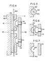
- the wire electrode 104 in the corresponding portion passes through the inside of the cold reserving tubes 120 and 121, and since the heat of that portion inside thereof is absorbed by the cooling tubes 120 and 121, an increase in temperature is suppressed.
- the portion locating at the gap between both cooling tubes becomes high temperature, resulting in a reduction of the tensile strength and an increase in elongation percentage, so that the wire electrode 104 is cut at this portion.
- the details of the cooling tubes 120 and 121 are illustrated in Figs. 4 to 7.
- the wire electrode can be smoothly cut without being affected due to a rush current, shock, or the like of the motor 126.
- the wire electrode 104 thus cut is wound by "the capstan 124 and then the workpiece 103 of which the work has been finished is replaced by a new one.
- the capstans 106 and 124 are again rotated and the free edge portion of the wire electrode 104 remaining in the gap between the cooling tubes 120 and 121 passes through the inside of the cooling tubes 121 and drops. Thereafter, it sequentially passes through the electrode fetching guide 134 and die-type electrode guide 138, and if necessary, it passes through a small hole formed at the work starting point in the workpiece 103, then passes through the electrode fetching guide 123 and enters the lower arm 102. The wire electrode 104 then enters the pass between the capstan 124 and the pinch roller 125 and is caught. Thereafter, it is introduced to a collecting apparatus (not shown) by a well-known pulling apparatus (not shown).
- This embodiment is separately provided from the electrode feeding mechanism for spark erosion such as the above-mentioned capstan 106 or the like.
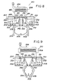
- a reference numeral 210 represents a wire cutting apparatus.
- Its base 201 has a rectangular shape which is long in the moving direction of the wire electrode and has a projection 211 at its peripheral edge porion on the longitudinal side, and its vertical cross section in the longitudinal direction is U-shaped, and is a member made of non-conductive material.
- a pair of L-character like moving-members 202 and 203 consisting of non-conductive material are respectively slidably supported in the longitudinal direction in the concave portion of the base 201 by means of a plurality of guide rollers 212 and 212 attached to the base 201.
- stoppers for preventing these moving members 202 and 203 from mutually approaching from the locations shown in Fig. 8 and springs adapted to press these moving members 202 and 203 toward the stoppers.
- Wedge-shaped electrode members 221 and 231 each consisting of conductive material are fixedly adhered to each one end of the moving members 202 and 203.
- swinging pressure members222 and 232 are attached to the locations at which they face those electrode members and are detachable so that they are rotatable by pivotal axes 209 and 209.
- a pair of bent levers 204 and 205 which respectively have rollers 241 and 251 at their points are attached between the moving members 202 and 203 so that they can be freely opened and closed by opening-closing fulcrum axes 242 and 252 mounted at the peripheral edge portion of the base 201.
- the rollers 241 and 251 are abut on the swinging pressure members 222 and 232, respectively.
- a leaf spring 206 is interposed between the handles of the levers 204 and 205, so that the levers 204 and 205 are subject to the elastic force in the direction such that their handles are opened.
- the levers are positioned at its maximum opening locations, namely at the moving end positions to be restricted by stoppers (not shown).
- springs are also interposed between the moving member 202 and the swinging pressure member 222 and between the moving member 203 and the swinging pressure member 232. These springs serve to act the elastic forces thereon in the direction so as to respectively detach the swinging pressure members 222 and 232 from the electrode members 221 and 231, thereby to come into contact with the rollers 241 and 251. Therefore, in the state shown in Fig. 8, microgaps through which a wire electrode 207 can pass almost rectilinearly as a whole are formed between the moving members 202 and 203 and the swinging pressure members 222 and 232. Upon spark erosion, the wire electrode 207 is inserted therein.
- a limit switch 283 is attached to the swinging pressure member 222. This limit switch 283 is turned on when the swinging pressure member 222 moves for a constant microdistance from the position shown in Fig. 8 to the left in the drawing.
- the electrode members 221 and 231 are connected through the limit switch 283 to the secondary side of a transformer 208.
- the primary side of the transformer 208 is connected through a cord 284 to a commercial power source.
- a DC power source and a controlled pulse power source may be of course, substituted for the transformer 208 as a power source to heat the wire electrode. It may be also possible to heat using an electric discharge circuit consisting of a capacitor to be charged by a direct current which is gotten by rectification of commercial electric power and a switching device which can control the discharge of said capacitor.
- these heating power sources should be set or controlled so as not to cause fusion, vaporizing explosion, or the like due to overheating in dependence upon material, diameter, length, or the like of a wire-electrode.
- Fig. 8 can be also used as an apparatus of the manually operating handy type, it may be also possible to use it attaching to fixed locations of a pair of arm holding column of the wire-cut electric discharge machine. In such a case, it can be constituted such that the cutting machine is placed to a proper location during the spark erosion and upon cutting operation of the wire-electrode, it is moved to a suitable cutting portion, thereby manually or automatically cutting the wire electrode. Furthermore, the operations of the levers 204 and 205, or the like and the power control or the like can be also controlled by a sequential control apparatus or the like.
- a tensile force to be applied to the wire electrode and a magnitude of a current flowing therethrough; however, for example, in case of a brass wire having a diameter of 0.2 mm, it is recommended to apply the tensile force of about 1.8-1.9 kg and heat the wire electrode by passing a peak current of 30-150 A therethrough.
- the wire electrode when a discharge energy of the capacitor is set to be extremely large, the wire electrode might have been fused and cut from the portion that become thin or the like, or otherwise it may further explosively vaporized and fused. Such a situation is unpreferable since the cutting portion is melted and solidified like a droplet and a large burr occurs and an oxidized decomposed portion or the like can be also caused.
- tension detecting mechanism it is possible to adopt other various kinds of well-known mechanical, electrical, or electromechanical methods in place of the above-mentioned method of measuring a motor driving current for driving the capstans.
- a method of supplying power to and heating the wire electrode it is possible to divisionally discharge a number of times from the capacitor by switching the switch a number of times or to repeat the charge and discharge a plurality of times. Furthermore, it is possible to construct such that the electrostatic capacity and/or charging voltage of the capacitor can be switched over and selected. It may be also possible to turning on and off a pulse power source which enables easy control of a heating current, for example a DC voltage source by a switching device and to use by pulse-width modulating these on-off signals.
- the wire electrode cutting apparatus according to the present invention is constructed as described above; therefore, this can be installed by slightly modifying the wire-cut electric discharge machine that has been already used.
- the wire electrode cutting apparatus since constant quantities of power and heat are applied to the wire electrode to be cut under a predetermined tensile force, as a conventional well-known cutter, the wire electrode is cut in the most ideal conditions such that the shape and physical property of the cutting portion are constant and no burr exists, and that the end portion is linearly elongated and is appropriately hardened. Therefore, the wire-electrode can be extremely easily inserted through the guides and nozzles or the like of the electric discharge machine of through a small hole formed in a workpiece.
- the wire electrode cutting apparatus according to the present invention is particularly suitable to be installed to an electric discharge machine which is provided with an automatically wire inserting or threading apparatus.
Landscapes
- Chemical & Material Sciences (AREA)
- Chemical Kinetics & Catalysis (AREA)
- Electrochemistry (AREA)
- Engineering & Computer Science (AREA)
- Mechanical Engineering (AREA)
- Electrical Discharge Machining, Electrochemical Machining, And Combined Machining (AREA)
Applications Claiming Priority (4)
| Application Number | Priority Date | Filing Date | Title |
|---|---|---|---|
| JP6248382U JPS58164700U (ja) | 1982-04-28 | 1982-04-28 | ワイヤ切断器 |
| JP62483/82U | 1982-04-28 | ||
| JP7000382U JPS58175880U (ja) | 1982-05-13 | 1982-05-13 | ワイヤ電極切断装置 |
| JP70003/82U | 1982-05-13 |
Publications (3)
| Publication Number | Publication Date |
|---|---|
| EP0107737A1 true EP0107737A1 (de) | 1984-05-09 |
| EP0107737A4 EP0107737A4 (de) | 1986-05-14 |
| EP0107737B1 EP0107737B1 (de) | 1990-09-19 |
Family
ID=26403525
Family Applications (1)
| Application Number | Title | Priority Date | Filing Date |
|---|---|---|---|
| EP83901393A Expired EP0107737B1 (de) | 1982-04-28 | 1983-04-28 | Drahtschneidelektrode für funkenerosive drahtschneidmaschine |
Country Status (5)
| Country | Link |
|---|---|
| EP (1) | EP0107737B1 (de) |
| AU (1) | AU570410B2 (de) |
| DE (1) | DE3342785C2 (de) |
| GB (1) | GB2130951B (de) |
| WO (1) | WO1983003789A1 (de) |
Cited By (2)
| Publication number | Priority date | Publication date | Assignee | Title |
|---|---|---|---|---|
| EP0220436A3 (en) * | 1985-09-16 | 1988-07-27 | Charmilles Technologies Sa | Device for straightening and cutting a metal wire |
| WO2021263121A1 (en) * | 2020-06-25 | 2021-12-30 | Jabil Inc. | Apparatus, system and method for cutting and delivering stamped contacts |
Families Citing this family (1)
| Publication number | Priority date | Publication date | Assignee | Title |
|---|---|---|---|---|
| CN117943643A (zh) * | 2024-02-27 | 2024-04-30 | 泰州市巨久不锈钢有限公司 | 一种不锈钢板局部加热切割装置 |
Family Cites Families (3)
| Publication number | Priority date | Publication date | Assignee | Title |
|---|---|---|---|---|
| JPS5676338A (en) * | 1979-11-21 | 1981-06-23 | Inoue Japax Res Inc | Method and apparatus for wire cut discharge type machining |
| DE3037505A1 (de) * | 1979-10-04 | 1981-04-16 | Inoue-Japax Research Inc., Yokohama, Kanagawa | Verfahren und vorrichtung zum drahtschneiden eines werkstueckes durch elektroerosion |
| CH633471A5 (fr) * | 1980-01-08 | 1982-12-15 | Charmilles Sa Ateliers | Machine pour usiner par etincelage erosif. |
-
1983
- 1983-04-28 EP EP83901393A patent/EP0107737B1/de not_active Expired
- 1983-04-28 AU AU15133/83A patent/AU570410B2/en not_active Ceased
- 1983-04-28 GB GB08333377A patent/GB2130951B/en not_active Expired
- 1983-04-28 DE DE19833342785 patent/DE3342785C2/de not_active Expired - Lifetime
- 1983-04-28 WO PCT/JP1983/000134 patent/WO1983003789A1/ja not_active Ceased
Non-Patent Citations (2)
| Title |
|---|
| No further relevant documents disclosed * |
| See also references of WO8303789A1 * |
Cited By (3)
| Publication number | Priority date | Publication date | Assignee | Title |
|---|---|---|---|---|
| EP0220436A3 (en) * | 1985-09-16 | 1988-07-27 | Charmilles Technologies Sa | Device for straightening and cutting a metal wire |
| WO2021263121A1 (en) * | 2020-06-25 | 2021-12-30 | Jabil Inc. | Apparatus, system and method for cutting and delivering stamped contacts |
| US12330898B2 (en) | 2020-06-25 | 2025-06-17 | Jabil Inc. | Apparatus, system and method for cutting and delivering stamped contacts |
Also Published As
| Publication number | Publication date |
|---|---|
| GB2130951A (en) | 1984-06-13 |
| DE3342785C2 (de) | 1993-08-12 |
| GB2130951B (en) | 1986-12-03 |
| GB8333377D0 (en) | 1984-01-18 |
| AU570410B2 (en) | 1988-03-17 |
| AU1513383A (en) | 1983-11-21 |
| EP0107737B1 (de) | 1990-09-19 |
| WO1983003789A1 (fr) | 1983-11-10 |
| EP0107737A4 (de) | 1986-05-14 |
| DE3342785T1 (de) | 1984-04-05 |
Similar Documents
| Publication | Publication Date | Title |
|---|---|---|
| US4618761A (en) | Electrode cutting apparatus for wire cut electric discharge machine | |
| US4367392A (en) | Automatic electrode wire rethreading device for travelling wire EDM apparatus | |
| US3987270A (en) | Automatic set-up electroerosion machining method and apparatus | |
| US3891819A (en) | Automatic set-up electroerosion machining method | |
| US4379959A (en) | Method of and apparatus for wire-cutting a workpiece by electroerosion | |
| EP0371724A1 (de) | Verfahren zum automatischen Zuführen eines Drahtes einer Elektroerosionsmaschine | |
| US4645894A (en) | Travelling wire EDM apparatus provided with electrode wire changer | |
| JPS6331334B2 (de) | ||
| JPH0253528A (ja) | ワイヤ放電加工機の結線方法 | |
| JP2553512B2 (ja) | 加工スリツト内に電極線を再度通すための手法とその応用装置 | |
| JPH0957539A (ja) | ワイヤ放電加工方法 | |
| US20080142487A1 (en) | Automatic Wire Threader | |
| EP0107737B1 (de) | Drahtschneidelektrode für funkenerosive drahtschneidmaschine | |
| EP0581493B1 (de) | Verfahren und Ausrüstung für den automatischen Übergang des zugeführten Drahtes in einer Funkenerosionsmaschine | |
| JPH0125654B2 (de) | ||
| JPS6137048B2 (de) | ||
| JP2518040B2 (ja) | ワイヤカット放電加工におけるワイヤ電極の切断処理装置及び切断処理方法 | |
| JPS58132420A (ja) | ワイヤカツト放電加工機におけるワイヤセツト方法及び装置 | |
| RU2470754C2 (ru) | Способ и устройство для формирования конца сварочного электрода | |
| US4980531A (en) | Prehesive device for the electrode wire of an EDM cutting machine | |
| JPS6341697B2 (de) | ||
| US20070295699A1 (en) | Multi-level welding position controller | |
| JP2680368B2 (ja) | ワイヤ放電加工機の結線作業時のワイヤ電極の座屈検出装置 | |
| US4378083A (en) | Wiring machine wire placing head | |
| JPH0525613B2 (de) |
Legal Events
| Date | Code | Title | Description |
|---|---|---|---|
| PUAI | Public reference made under article 153(3) epc to a published international application that has entered the european phase |
Free format text: ORIGINAL CODE: 0009012 |
|
| AK | Designated contracting states |
Designated state(s): FR |
|
| 17P | Request for examination filed |
Effective date: 19840330 |
|
| A4 | Supplementary search report drawn up and despatched |
Effective date: 19860514 |
|
| 17Q | First examination report despatched |
Effective date: 19871116 |
|
| GRAA | (expected) grant |
Free format text: ORIGINAL CODE: 0009210 |
|
| AK | Designated contracting states |
Kind code of ref document: B1 Designated state(s): FR |
|
| ET | Fr: translation filed | ||
| PLBE | No opposition filed within time limit |
Free format text: ORIGINAL CODE: 0009261 |
|
| STAA | Information on the status of an ep patent application or granted ep patent |
Free format text: STATUS: NO OPPOSITION FILED WITHIN TIME LIMIT |
|
| 26N | No opposition filed | ||
| PGFP | Annual fee paid to national office [announced via postgrant information from national office to epo] |
Ref country code: FR Payment date: 20000411 Year of fee payment: 18 |
|
| PG25 | Lapsed in a contracting state [announced via postgrant information from national office to epo] |
Ref country code: FR Free format text: THE PATENT HAS BEEN ANNULLED BY A DECISION OF A NATIONAL AUTHORITY Effective date: 20010430 |
|
| REG | Reference to a national code |
Ref country code: FR Ref legal event code: ST |