EP0107986B1 - Verfahren und Vorrichtung zur Wasserstoffumwandlung von Kohlenwasserstoffen - Google Patents
Verfahren und Vorrichtung zur Wasserstoffumwandlung von Kohlenwasserstoffen Download PDFInfo
- Publication number
- EP0107986B1 EP0107986B1 EP83401818A EP83401818A EP0107986B1 EP 0107986 B1 EP0107986 B1 EP 0107986B1 EP 83401818 A EP83401818 A EP 83401818A EP 83401818 A EP83401818 A EP 83401818A EP 0107986 B1 EP0107986 B1 EP 0107986B1
- Authority
- EP
- European Patent Office
- Prior art keywords
- fluid
- reactor
- zone
- catalyst
- funnel
- Prior art date
- Legal status (The legal status is an assumption and is not a legal conclusion. Google has not performed a legal analysis and makes no representation as to the accuracy of the status listed.)
- Expired
Links
- 238000000034 method Methods 0.000 title claims description 43
- 230000008569 process Effects 0.000 title claims description 37
- 229930195733 hydrocarbon Natural products 0.000 title claims description 11
- 150000002430 hydrocarbons Chemical class 0.000 title claims description 11
- 239000012530 fluid Substances 0.000 claims description 70
- 239000003054 catalyst Substances 0.000 claims description 62
- 239000002245 particle Substances 0.000 claims description 31
- 238000009826 distribution Methods 0.000 claims description 30
- 239000007788 liquid Substances 0.000 claims description 28
- 238000006243 chemical reaction Methods 0.000 claims description 22
- 239000007789 gas Substances 0.000 claims description 19
- 239000007787 solid Substances 0.000 claims description 17
- 239000007791 liquid phase Substances 0.000 claims description 11
- 239000007792 gaseous phase Substances 0.000 claims description 10
- 239000001257 hydrogen Substances 0.000 claims description 10
- 229910052739 hydrogen Inorganic materials 0.000 claims description 10
- 230000004888 barrier function Effects 0.000 claims description 7
- 238000010791 quenching Methods 0.000 claims description 5
- 238000007599 discharging Methods 0.000 claims 14
- 230000001174 ascending effect Effects 0.000 claims 8
- 239000004215 Carbon black (E152) Substances 0.000 claims 4
- 125000004435 hydrogen atom Chemical class [H]* 0.000 claims 4
- 239000011949 solid catalyst Substances 0.000 claims 4
- 230000001413 cellular effect Effects 0.000 claims 3
- 230000000149 penetrating effect Effects 0.000 claims 2
- 230000000694 effects Effects 0.000 claims 1
- 230000003197 catalytic effect Effects 0.000 description 36
- 239000006185 dispersion Substances 0.000 description 7
- 238000011282 treatment Methods 0.000 description 7
- UFHFLCQGNIYNRP-UHFFFAOYSA-N Hydrogen Chemical compound [H][H] UFHFLCQGNIYNRP-UHFFFAOYSA-N 0.000 description 6
- 230000006872 improvement Effects 0.000 description 6
- 239000012071 phase Substances 0.000 description 5
- 238000002347 injection Methods 0.000 description 4
- 239000007924 injection Substances 0.000 description 4
- 150000004945 aromatic hydrocarbons Chemical class 0.000 description 2
- 150000001875 compounds Chemical class 0.000 description 2
- 238000010276 construction Methods 0.000 description 2
- 230000009849 deactivation Effects 0.000 description 2
- 239000010432 diamond Substances 0.000 description 2
- 230000005484 gravity Effects 0.000 description 2
- 229910052751 metal Inorganic materials 0.000 description 2
- 239000002184 metal Substances 0.000 description 2
- 239000000203 mixture Substances 0.000 description 2
- 230000000750 progressive effect Effects 0.000 description 2
- 241000283153 Cetacea Species 0.000 description 1
- 238000009825 accumulation Methods 0.000 description 1
- 230000029936 alkylation Effects 0.000 description 1
- 238000005804 alkylation reaction Methods 0.000 description 1
- 239000000956 alloy Substances 0.000 description 1
- 229910045601 alloy Inorganic materials 0.000 description 1
- 239000011324 bead Substances 0.000 description 1
- 230000015572 biosynthetic process Effects 0.000 description 1
- 230000000903 blocking effect Effects 0.000 description 1
- 238000004517 catalytic hydrocracking Methods 0.000 description 1
- 239000000571 coke Substances 0.000 description 1
- 238000004939 coking Methods 0.000 description 1
- 238000001816 cooling Methods 0.000 description 1
- 238000005336 cracking Methods 0.000 description 1
- 238000006356 dehydrogenation reaction Methods 0.000 description 1
- 230000008021 deposition Effects 0.000 description 1
- 238000006477 desulfuration reaction Methods 0.000 description 1
- 230000023556 desulfurization Effects 0.000 description 1
- 238000004821 distillation Methods 0.000 description 1
- 230000003628 erosive effect Effects 0.000 description 1
- 238000005984 hydrogenation reaction Methods 0.000 description 1
- 230000001788 irregular Effects 0.000 description 1
- 238000006317 isomerization reaction Methods 0.000 description 1
- 238000004519 manufacturing process Methods 0.000 description 1
- 150000002739 metals Chemical class 0.000 description 1
- 230000005012 migration Effects 0.000 description 1
- 238000013508 migration Methods 0.000 description 1
- 230000000737 periodic effect Effects 0.000 description 1
- 239000003208 petroleum Substances 0.000 description 1
- 239000004033 plastic Substances 0.000 description 1
- 239000002574 poison Substances 0.000 description 1
- 231100000614 poison Toxicity 0.000 description 1
- 230000000171 quenching effect Effects 0.000 description 1
- 230000000284 resting effect Effects 0.000 description 1
- 238000000926 separation method Methods 0.000 description 1
- 230000009897 systematic effect Effects 0.000 description 1
- 238000010555 transalkylation reaction Methods 0.000 description 1
- 230000009466 transformation Effects 0.000 description 1
- 235000012773 waffles Nutrition 0.000 description 1
Images



Classifications
-
- C—CHEMISTRY; METALLURGY
- C10—PETROLEUM, GAS OR COKE INDUSTRIES; TECHNICAL GASES CONTAINING CARBON MONOXIDE; FUELS; LUBRICANTS; PEAT
- C10G—CRACKING HYDROCARBON OILS; PRODUCTION OF LIQUID HYDROCARBON MIXTURES, e.g. BY DESTRUCTIVE HYDROGENATION, OLIGOMERISATION, POLYMERISATION; RECOVERY OF HYDROCARBON OILS FROM OIL-SHALE, OIL-SAND, OR GASES; REFINING MIXTURES MAINLY CONSISTING OF HYDROCARBONS; REFORMING OF NAPHTHA; MINERAL WAXES
- C10G49/00—Treatment of hydrocarbon oils, in the presence of hydrogen or hydrogen-generating compounds, not provided for in a single one of groups C10G45/02, C10G45/32, C10G45/44, C10G45/58 or C10G47/00
- C10G49/10—Treatment of hydrocarbon oils, in the presence of hydrogen or hydrogen-generating compounds, not provided for in a single one of groups C10G45/02, C10G45/32, C10G45/44, C10G45/58 or C10G47/00 with moving solid particles
- C10G49/14—Treatment of hydrocarbon oils, in the presence of hydrogen or hydrogen-generating compounds, not provided for in a single one of groups C10G45/02, C10G45/32, C10G45/44, C10G45/58 or C10G47/00 with moving solid particles according to the "moving-bed" technique
-
- B—PERFORMING OPERATIONS; TRANSPORTING
- B01—PHYSICAL OR CHEMICAL PROCESSES OR APPARATUS IN GENERAL
- B01J—CHEMICAL OR PHYSICAL PROCESSES, e.g. CATALYSIS OR COLLOID CHEMISTRY; THEIR RELEVANT APPARATUS
- B01J8/00—Chemical or physical processes in general, conducted in the presence of fluids and solid particles; Apparatus for such processes
- B01J8/08—Chemical or physical processes in general, conducted in the presence of fluids and solid particles; Apparatus for such processes with moving particles
- B01J8/12—Chemical or physical processes in general, conducted in the presence of fluids and solid particles; Apparatus for such processes with moving particles moved by gravity in a downward flow
-
- C—CHEMISTRY; METALLURGY
- C10—PETROLEUM, GAS OR COKE INDUSTRIES; TECHNICAL GASES CONTAINING CARBON MONOXIDE; FUELS; LUBRICANTS; PEAT
- C10G—CRACKING HYDROCARBON OILS; PRODUCTION OF LIQUID HYDROCARBON MIXTURES, e.g. BY DESTRUCTIVE HYDROGENATION, OLIGOMERISATION, POLYMERISATION; RECOVERY OF HYDROCARBON OILS FROM OIL-SHALE, OIL-SAND, OR GASES; REFINING MIXTURES MAINLY CONSISTING OF HYDROCARBONS; REFORMING OF NAPHTHA; MINERAL WAXES
- C10G49/00—Treatment of hydrocarbon oils, in the presence of hydrogen or hydrogen-generating compounds, not provided for in a single one of groups C10G45/02, C10G45/32, C10G45/44, C10G45/58 or C10G47/00
- C10G49/002—Apparatus for fixed bed hydrotreatment processes
Definitions
- the present invention relates to a process and devices for catalytic treatment (or hydrotreatment) of a fluid charge and more particularly of demetallization, desulfurization, hydrotreatment and conversion or hydroconversion of hydrocarbons, in a fixed or mobile bed such as explained below.
- the invention is particularly applicable to catalytic treatments of liquid feedstocks, such as, for example, distillates from heavy petroleum crudes, residues from the distillation of atmospheric hydrocarbons and under vacuum, these treatments generally being carried out in the presence of hydrogen and / or of hydrogen-rich gas mixtures, on a solid catalytic converter, the catalytic converter being used in the form of particles (extruded catalyst, grains of various shapes, beads, etc.).
- the fresh catalyst is introduced into the upper part of the reactor; the system for injecting the charge and the hydrogen together in the form of a mixed fluid which travels from the bottom to the top of the reactor, is the subject of the present invention.
- the process according to the invention and the devices according to the invention are therefore suitable for injecting a feedstock and for withdrawing catalytic particles from cracking, hydrocracking, hydroreforming reactors, for the production of aromatic hydrocarbons, of isomerization of paraffinic, naphthenic or aromatic hydrocarbons, the various reactions of hydrogenation, hydrotreatment, dehydrogenation, alkylation, transalkylation, hydrodecyclization, hydrodealkylation, hydrovisco-reduction treatments , etc., reactors where the charge and / or the gases which are injected into it, travel from bottom to top.
- the fluid charge which is a mixture of a liquid and a gas, is introduced into the reactor or the enclosure containing catalytic particles by distribution members located at the bottom of the reactor or of the enclosure and circulates at counter-current of the catalyst from bottom to top (“up-flow”) before being evacuated, after its treatment, to the upper part of the reactor (or of the enclosure which is arbitrarily designated “reactor” in the following) of this description).
- up-flow bottom to top
- the flow of the catalyst by gravity, ensures a regular descent of the catalytic bed, while the upward circulation of the fluid charge allows in particular an easy adjustment of the residence time and ensures a controlled backwash of the bed.
- the countercurrent circulation of the feedstock and the catalyst makes it possible to obtain a high catalytic conversion since the fresh catalyst introduced at the top of the reactor processes an almost converted feedstock (that is to say essentially containing compounds of which transformation is difficult), while at the bottom of the reactor, the spent catalyst processes a fresh feed (that is to say rich in compounds which are easy to transform), which efficiently carries out the first stages of the conversion.
- US Pat. No. 3,826,737 discloses a process for catalytic conversion in a moving bed. This process is however more particularly adapted to the cocurrent circulation of the catalyst and the liquid charge, the latter being evacuated at the base of the reactor through a cylindrical grid disposed at the base of a catalyst discharge cone and which supports the bed. catalytic.
- Such a method has the disadvantage of a risk of fouling of the grid by grains of catalyst pushed against this grid by the liquid charge discharged from the bottom of the reactor. This can then result in an irregular distribution of the fluids in the catalyst, difficulties in the flow of the catalytic bed, with the risk of blocking certain zones of this bed, as well as an increase in the erosion of the catalyst due to the friction between blocked grains and free grains of the catalytic bed and between the free catalyst grains and the liquid charge discharge grid.
- the object of the invention is to provide a technique which overcomes the drawbacks mentioned above.
- This technique consists in injecting the liquid and the gases under the wall which supports the catalytic bed, through a plurality of orifices distributed over the section of the reactor, in accordance with various arrangements which are the subject of the invention.
- this result is obtained by a process (with progressive withdrawal of the pulverulent solid particles from a generally closed space) for introducing into said space a fluid charge consisting of a liquid and a gas (generally hydrogen) said generally closed space having substantially the shape of an elongated and substantially vertical volume of revolution, the solid particles being introduced into the upper part of the enclosure and gradually withdrawn into the lower part of the enclosure after having traveled from top to bottom in said enclosure, while the fluid charge is introduced at least in part and generally continuously into the lower part of said enclosure and is withdrawn therefrom in the upper part after having traveled from bottom to top in said enclosure, process in which the solid particles are gradually withdrawn by the lower end of at least one flared zone having a shape depending on the geometry of the reactor and in general the shape of an inverted cone or an inverted pyramid, c '' is to say of a cone or a pyramid whose apex is turned downwards, apex in which is pierced an opening of size suitable for the evacuation of solid particles, the wall of said flared
- a first type of distribution zone consists of a main pipe which is for example substantially horizontal or vertical when it enters the interior of the reactor, said pipe possibly forming at least one bend, its end (or end piece) then becoming substantially vertical under the wall of the flared zone which supports the catalytic bed.
- This nozzle is then subdivided into a plurality of branches (or spokes) arranged (toroidal distribution type and tube network) for example in a star (with at least 3 branches or spokes) each branch being provided with several orifices judiciously arranged (looking at the wall or arranged opposite or on the sides of the branch) all along the branch and through which the mixed fluid is injected in order to uniformly reach the catalytic bed, that is to say by irrigating it with homogeneously.
- branches or spokes arranged (toroidal distribution type and tube network) for example in a star (with at least 3 branches or spokes) each branch being provided with several orifices judiciously arranged (looking at the wall or arranged opposite or on the sides of the branch) all along the branch and through which the mixed fluid is injected in order to uniformly reach the catalytic bed, that is to say by irrigating it with homogeneously.
- the reactor 1 which may be of the radial or axial type, has at its upper part means for progressive introduction of catalyst (new or regenerated) shown diagrammatically by the conduit 2 which pours the catalyst particles to feed a fixed catalyst bed 3 or mobile.
- the catalyst flows by gravity into the reactor and is gradually evacuated via line 4, at the bottom of the reactor 1, by means of a withdrawal funnel 5 which, in the figure, appears in the appearance of a grid.
- This funnel here in the shape of an inverted cone, is therefore provided with openings such as 6, formed by the perforated spaces of the grid 5 which allow the liquid and gaseous charge injected to pass below the level of the grid or funnel 5 by a pipe such as 7, but do not allow the particles of the catalyst to pass.
- the angle a made by the axis of the cone (or the axis of the pyramid if the funnel has this shape) with one of the generatrices of the cone (or one of the edges of the pyramid) is generally between 10 and 80 °, preferably between 20 and 50 °.
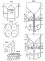
- the fluid charge consisting of two phases (liquid and gas), is therefore introduced into the lower part of the reactor 1 by at least one distribution zone comprising a distribution ramp 7 (horizontal, oblique or vertical or disposed in any suitable manner, for example vertical in certain industrial reactors) which feeds at least one vertical injection rod 8 from which radiate tubes 9 (or branches) arranged in a star as shown in FIG. 1 A, which is a cross section of reactor 1.
- a distribution ramp 7 horizontal, oblique or vertical or disposed in any suitable manner, for example vertical in certain industrial reactors
- FIG. 1 A which is a cross section of reactor 1.
- each branch 9 of the star 10 is provided with orifices 12 (holes or slots or other perforations of the same type) for the injection of the fluid charge inside the reaction zone.
- the charge-fluid, formed of two phases (liquid and gas) rises in the reactor against the current of the catalyst before being evacuated to the upper part of the reactor by means of collection and evacuation schematized by the pipe 11 , having the form, for example, of a rake consisting of collecting tubes connected to a discharge pipe.
- a ramp here horizontal 7 at least one end piece (or rod) 8 vertical and the branches 9 of various shapes.
- These branches represent either a star with inclined branches in FIG. 2 (or in the shape of an inverted umbrella whale), a star with shaped branches wavy in fig. 3.
- Fig. 4 shows the possible positions of the orifices such as 12 on a branch 9 with the aim of sending in multiple directions (shown schematically by the arrows 13 in all of FIGS. 1,2,3 and 4) the droplets of fluid in view to make them penetrate the catalytic mass homogeneously at any point on the surface of the grid or wall 5, through the openings 6 in FIG. 1.
- Distributor stars may have 3,4,5,6,7,8, etc., or more, of branches or spokes.
- Figs. 5 and 5A schematically illustrate an embodiment in which the evacuation of the catalyst is carried out by several withdrawal funnels. There is shown in these figs. 5 and 5A, only the bottom of a reactor 1 and the funnels such as 5 and in FIG. 5, a single rod and a single ramp 7. The sectional view 5A thus shows 4 funnels, only two of them being visible in FIG. 5, in axial section.
- the number of withdrawal funnels 4 depends on the geometry of the reactor, the mechanical construction constraints and the uniformity of the paths desired for the catalytic particles which pass through the various sectors of the reactor.
- Such a withdrawal mode makes it possible to easily adjust the catalyst flow rate, independently of that of the fluid charge and allows to carry out at will (in a moving bed) a continuous or discontinuous (that is to say periodic) withdrawal of the catalyst. .
- the mixed fluid injected by a distribution zone goes towards the funnel or the funnels which support the catalytic bed by first meeting before reaching this or these funnels, a space 18 (fig. 6), the upper part of which is provided with orifices large enough to let most of the gaseous phase of the mixed fluid pass but small enough to prevent the majority of the liquid phase of the mixed fluid from passing through, said space being crossed by vertical walls which delimit openings through said space, so that the mixed fluid, inside said space, divides on the one hand in gaseous phase and, on the other hand, in liquid phase , most of the gas phase reaching a funnel through said orifices of said upper part of the space, most of the liquid phase reaching a funnel after having traveled through said openings delimited by said vertical walls which cross said space, and after having mixed again (above said orifices in said upper part of space) with the major part of the gas phase in order to create contacts homogeneous and regular at all levels of the cata
- This improvement in the apparatus therefore makes it possible to obtain an even more regular dispersion of the fluid through the catalytic bed for a greater flow range.
- This improvement illustrated in FIG. 6 consists in having, in the reactor 1, between the grid 5, which supports the catalytic bed (withdrawal of the catalyst by the conduit 4) and the ramps such as 7, distribution zones of star shape or not (which one shown diagrammatically by the discs 8), an additional grid 14 (or any other equivalent means), the perforations 20 of which are small enough not to allow most of the liquid phase of the fluid to pass (introduced by the distribution zones 8), thus only allowing most of the gaseous phase of the fluid to pass.
- Continuous or substantially vertical walls or barriers 15 that is to say non-perforated or non-perforated), in the form of chimneys for example, are disposed, in a generally regular manner under this grid 14 by resting on this grid 14 (and whose lower ends are located sufficiently low in the reactor, generally at a level higher than that of the distribution zones 8) and thus delimit a compartment 18 and chimneys 19: the gaseous fraction of the fluid reached for the most part ( arrows 17) the grid 5 through the compartment 18 and the orifices 20, after having passed through zones 22 of accumulation and separation of a liquid phase and a gaseous phase.
- Trays or baffles 21 are arranged under the lower ends of the chimneys 19 (and above the level of the distribution zones) so that the mixed fluid injected by the distribution zones 8 and whose path is materialized by the arrows 13, accumulates in the compartments 18 creating liquid and gaseous clusters 22, most of the liquid rushing through the chimneys 19 (path materialized by the arrows 16).
- the improvement described above therefore acts as a mixer and for dispersing the fluid charge.
- the devices of fig. 6 can be further improved. It has in fact been noted that the gases, the path of which is materialized by arrows 17, tend to direct themselves and to accumulate in the angles ⁇ delimited by the walls of the funnel or funnels 5 and the wall of the reactor 1. To avoid the migration of gas under the upper part of the funnel and thus improve the distribution of gas and liquid throughout the section of the bed, the gas phase and the liquid phase (from the orifices of the upper part of said spaces) through a plurality of elongated non-communicating zones which are parallel and substantially vertical or oblique or partly vertical and partly oblique which thus oblige the gaseous particles to take a controlled path under the funnel or under the funnels.
- Fig. 7 illustrates this improvement: there are all the accessories in FIG.
- a plurality of elongated vertical zones separated by vertical barriers 23 On the right side of FIG. 7, the lower ends of these barriers are all at the same level; these ends are at different levels on the left side of fig. 7.
- the length of the barriers and their level depend essentially on the geometry of the distribution areas.
- Fig. 7A shows, by way of nonlimiting example, a method of construction of these barriers 23 which here are cham bres or honeycomb or honeycomb type tubes. The upper part of these tubes is placed in the immediate vicinity of the funnel grid 5 and preferably in contact with this funnel grid.
- Fig. 7B illustrates barriers 23 which are vertical in their lower part and oblique in the vicinity of the grid 5 which supports the reactor.
- FIG. 8 or fig. 9 Another improvement of the process and of the apparatus in accordance with the invention and also serving as a mixer for the fluid charge, is illustrated in FIG. 8 or fig. 9 (in FIG. 9, the pipe 4 for withdrawing the catalyst has not been shown).
- This process consists in making the mixed fluid flow, injected by a distribution zone of star shape or not, through a plurality of honeycomb layers, juxtaposed to each other and arranged between the distribution zone or zones and the funnel or funnels which support the catalytic bed, in order to cause a regular and homogeneous distribution of the charge in the catalytic fit and to ensure the best dispersion of gas and liquid for a wide range of flow.
- the fluid injected into the reactor 1 is circulated towards the grid 5 and its perforations 6, by the distribution system 7 and 8, of star shape or not (and for example in FIG. 9, of shape "Jet breaker", that is to say an injection pipe with a plurality of orifices surmounted by at least one plate or plate 27 which breaks the jet in rain, as indicated by the arrows 25) through the cells of a kind of waffle mold 26, itself made up of a series of elements 24 having the form of honeycombed plates or layers of various shapes (cylindrical or square, etc., for example) depending on the geometry from the reactor and clamped against each other.
- shape "Jet breaker” that is to say an injection pipe with a plurality of orifices surmounted by at least one plate or plate 27 which breaks the jet in rain, as indicated by the arrows 25
- the cells of a kind of waffle mold 26 itself made up of a series of elements 24 having the form of honeycombed plates or layers of various shapes (cylindrical or square, etc
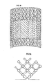
- each element has the shape of a rough or striated or fluted plate (usual English word: "corrugations") of ribs (as shown in fig. 10) and the plates, identical or different, are arranged to create paths complex (illustrated in FIGS. 8A and 9A) and continuous from the lower part to the upper part, allowing the mixed fluid to emerge at the upper part through a multitude of orifices and thus gain regular access over the entire section of the catalytic bed, through the funnel grid 5.
- each fluid path or path divides several times into two new paths, each of these new paths dividing in turn into other fluid paths.
- the plates whose general appearance is visible in fig. 10 are made of a suitable metal or alloy or plastic. They are found commercially ("Sulzer”, registered trademark).
- Fig. 11 illustrates an embodiment of this type of zone or distribution box. Everything happens as if the fluid was introduced into the reactor 1 through a kind of double wall integrated into the funnel grid.
- the charge is introduced by a conventional ramp 7 (which can be arranged in any suitable manner, horizontal or vertical most often in certain industrial reactors); the vertical pipe is a tube 8 of the same axis as that of the grid funnel 5, this tube opening at its upper part so as to form a second funnel 28 disposed in the vicinity of the perforated funnel 5 and under this funnel 5.
- quenches quenching or cooling
- a judiciously chosen liquid for example a liquid of the same kind as the feed, for example at the inlet or at the outlet of the reaction zone or else between the catalytic beds (because the processes and equipment described remain valid for superimposed catalytic beds) but also in the middle of one or more of the catalytic bed itself and in the latter case, it has proved to be judicious to inject the fluid used to make such a quench (cold hydrogen for example or cold liquid) using at least one distribution zone of star shape of the type described above for FIGS.
- Fig. 12 on which we recognize a star zone (7 and 8) for injecting the load (arrow 13) through a funnel-grid 5 in the bed 3, thus comprises two star zones 29 and 30 for performing quenches. The effluent is drawn off through line 11.
Landscapes
- Chemical & Material Sciences (AREA)
- Oil, Petroleum & Natural Gas (AREA)
- Chemical Kinetics & Catalysis (AREA)
- Organic Chemistry (AREA)
- Engineering & Computer Science (AREA)
- General Chemical & Material Sciences (AREA)
- Devices And Processes Conducted In The Presence Of Fluids And Solid Particles (AREA)
- Production Of Liquid Hydrocarbon Mixture For Refining Petroleum (AREA)
Claims (19)
Applications Claiming Priority (2)
| Application Number | Priority Date | Filing Date | Title |
|---|---|---|---|
| FR8216597 | 1982-10-04 | ||
| FR8216597A FR2533937B1 (fr) | 1982-10-04 | 1982-10-04 | Procede et dispositif d'hydroconversion d'hydrocarbures |
Publications (2)
| Publication Number | Publication Date |
|---|---|
| EP0107986A1 EP0107986A1 (de) | 1984-05-09 |
| EP0107986B1 true EP0107986B1 (de) | 1986-01-29 |
Family
ID=9277944
Family Applications (1)
| Application Number | Title | Priority Date | Filing Date |
|---|---|---|---|
| EP83401818A Expired EP0107986B1 (de) | 1982-10-04 | 1983-09-19 | Verfahren und Vorrichtung zur Wasserstoffumwandlung von Kohlenwasserstoffen |
Country Status (5)
| Country | Link |
|---|---|
| US (1) | US4571326A (de) |
| EP (1) | EP0107986B1 (de) |
| JP (1) | JPS5986692A (de) |
| DE (1) | DE3362031D1 (de) |
| FR (1) | FR2533937B1 (de) |
Families Citing this family (31)
| Publication number | Priority date | Publication date | Assignee | Title |
|---|---|---|---|---|
| US4968409A (en) * | 1984-03-21 | 1990-11-06 | Chevron Research Company | Hydrocarbon processing of gas containing feed in a countercurrent moving catalyst bed |
| FR2581564B1 (fr) * | 1985-05-13 | 1993-05-07 | Bp Chimie Sa | Appareil a lit fluidise comportant une grille de fluidisation a plusieurs pentes |
| US4664782A (en) * | 1986-01-09 | 1987-05-12 | Intevep, S.A. | Method for withdrawing particulate solid from a high pressure vessel |
| FR2633196B2 (fr) * | 1987-11-30 | 1991-05-31 | Inst Francais Du Petrole | Appareil pour injecter une charge d'hydrocarbures dans un reacteur |
| FR2623732B1 (fr) * | 1987-11-30 | 1990-05-04 | Inst Francais Du Petrole | Appareil pour injecter une charge d'hydrocarbures dans un reacteur |
| US4990241A (en) * | 1988-08-31 | 1991-02-05 | Amoco Corporation | Hydrotreating process to minimize catalyst slumping |
| US5916529A (en) * | 1989-07-19 | 1999-06-29 | Chevron U.S.A. Inc | Multistage moving-bed hydroprocessing reactor with separate catalyst addition and withdrawal systems for each stage, and method for hydroprocessing a hydrocarbon feed stream |
| US5076908A (en) * | 1989-07-19 | 1991-12-31 | Chevron Research & Technology Company | Method and apparatus for an on-stream particle replacement system for countercurrent contact of a gas and liquid feed stream with a packed bed |
| US5498327A (en) * | 1989-07-19 | 1996-03-12 | Stangeland; Bruce E. | Catalyst, method and apparatus for an on-stream particle replacement system for countercurrent contact of a gas and liquid feed stream with a packed bed |
| US5492617A (en) * | 1989-07-19 | 1996-02-20 | Trimble; Harold J. | Apparatus and method for quenching in hydroprocessing of a hydrocarbon feed stream |
| US5589057A (en) * | 1989-07-19 | 1996-12-31 | Chevron U.S.A. Inc. | Method for extending the life of hydroprocessing catalyst |
| US5472928A (en) * | 1989-07-19 | 1995-12-05 | Scheuerman; Georgieanna L. | Catalyst, method and apparatus for an on-stream particle replacement system for countercurrent contact of a gas and liquid feed stream with a packed bed |
| CA2040995A1 (en) * | 1990-05-16 | 1991-11-17 | Robert D. Buttke | Reduced gas holdup in catalytic reactor |
| US5603904A (en) * | 1993-06-18 | 1997-02-18 | Chevron U.S.A. Inc. | Apparatus for catalyst replacement |
| JP3431216B2 (ja) * | 1993-06-18 | 2003-07-28 | 千代田化工建設株式会社 | 触媒層支持構造 |
| US5723041A (en) * | 1994-10-10 | 1998-03-03 | Amoco Corporation | Process and apparatus for promoting annularly uniform flow |
| US5885534A (en) * | 1996-03-18 | 1999-03-23 | Chevron U.S.A. Inc. | Gas pocket distributor for hydroprocessing a hydrocarbon feed stream |
| US5879642A (en) * | 1996-04-24 | 1999-03-09 | Chevron U.S.A. Inc. | Fixed bed reactor assembly having a guard catalyst bed |
| US6086749A (en) * | 1996-12-23 | 2000-07-11 | Chevron U.S.A. Inc. | Catalyst and method for hydroprocessing a hydrocarbon feed stream in a reactor containing two or more catalysts |
| US6554994B1 (en) | 1999-04-13 | 2003-04-29 | Chevron U.S.A. Inc. | Upflow reactor system with layered catalyst bed for hydrotreating heavy feedstocks |
| US20030223924A1 (en) * | 2002-05-29 | 2003-12-04 | Bachtel Robert W. | Gas-pocket distributor and method of distributing gas |
| US20070140927A1 (en) * | 2005-12-16 | 2007-06-21 | Chevron U.S.A. Inc. | Reactor for use in upgrading heavy oil admixed with a highly active catalyst composition in a slurry |
| US8236170B2 (en) * | 2005-12-16 | 2012-08-07 | Chevron U.S.A. Inc. | Reactor for use in upgrading heavy oil |
| US8556238B2 (en) * | 2006-12-29 | 2013-10-15 | Econity Co., Ltd. | Diffuser for aeration |
| KR100778491B1 (ko) * | 2006-12-29 | 2007-11-28 | 주식회사 케이엠에스 | 폭기용 산기관 |
| US7901640B2 (en) * | 2008-05-13 | 2011-03-08 | Uop Llc | Optimized counter-current flow baffle |
| DE102011121188A1 (de) | 2011-12-16 | 2013-06-20 | Thyssen Krupp Uhde Gmbh | Vorrichtung und Verfahren zur Beseitigung von NOx und N20 |
| JP6267694B2 (ja) * | 2012-06-14 | 2018-01-24 | サウジ アラビアン オイル カンパニー | 温度勾配過程による原油の直接接触分解 |
| WO2016137955A1 (en) | 2015-02-27 | 2016-09-01 | Sabic Global Technologies B.V. | Minimizing coke formation in a reactor stripper |
| US11084003B2 (en) * | 2016-06-15 | 2021-08-10 | Satoshi ANZAI | Ultrafine bubble generation device for aquaculture or wastewater treatment |
| US11154793B2 (en) * | 2018-03-28 | 2021-10-26 | Uop Llc | Apparatus for gas-liquid contacting |
Family Cites Families (20)
| Publication number | Priority date | Publication date | Assignee | Title |
|---|---|---|---|---|
| NL79876C (de) * | 1900-01-01 | |||
| US2608474A (en) * | 1949-01-14 | 1952-08-26 | Shell Dev | Apparatus for contacting gaseous fluids with powdered solids |
| BE512379A (de) * | 1951-06-26 | |||
| BE528148A (de) * | 1953-04-21 | |||
| US2876079A (en) * | 1956-03-07 | 1959-03-03 | Exxon Research Engineering Co | Gas distributing arrangement for fluidized solids vessels |
| NL112468C (de) * | 1958-08-05 | |||
| GB1105614A (en) * | 1964-04-22 | 1968-03-06 | Ici Ltd | Catalytic converter |
| US3480265A (en) * | 1968-01-04 | 1969-11-25 | Vagn Deve | Shell sand treating apparatus and method |
| FR1564658A (de) * | 1968-02-13 | 1969-04-25 | ||
| DE1933857A1 (de) * | 1969-07-03 | 1971-01-21 | Atlantic Richfield Co | Verfahren zur Hydrierung von Kohlenwasserstoffen |
| GB1309427A (en) * | 1970-03-18 | 1973-03-14 | Air Prod & Chem | Upflow catalytic reactor and method |
| US3829983A (en) * | 1971-10-27 | 1974-08-20 | Phillips Petroleum Co | Grid plate |
| FR2313649A1 (fr) * | 1975-06-20 | 1976-12-31 | Kao Corp | Appareil pour chauffer ou refroidir du sable |
| HU172289B (hu) * | 1975-12-09 | 1978-07-28 | Richter Gedeon Vegyeszet | Mekhanizm dlja sozdanija psevdozhidkogo sloja pri sushke sypuchikh tvjordykh materialov |
| DE2721182A1 (de) * | 1977-05-11 | 1978-11-23 | Nukem Gmbh | Wirbelschichtreaktor zur aufarbeitung von kohlenstoffbeschichteten partikeln |
| NL7711019A (nl) * | 1977-10-07 | 1979-04-10 | Shell Int Research | Inrichting voor katalytische behandeling van koolwaterstoffen. |
| FR2460990A1 (fr) * | 1979-07-09 | 1981-01-30 | Inst Francais Du Petrole | Procede et appareil de conversion catalytique d'hydrocarbures |
| FR2480137A1 (fr) * | 1980-04-09 | 1981-10-16 | Saint Gobain Vitrage | Lit fluidise pour le traitement thermique de materiaux, notamment du verre |
| FR2504821B1 (fr) * | 1981-04-29 | 1986-05-02 | Inst Francais Du Petrole | Procede et dispositif pour soutirer des particules solides et introduire une charge liquide a la partie inferieure d'une zone de contact |
| IT1193589B (it) * | 1982-01-29 | 1988-07-08 | Montedison Spa | Distributore di gas per letti fluidizzati |
-
1982
- 1982-10-04 FR FR8216597A patent/FR2533937B1/fr not_active Expired
-
1983
- 1983-09-19 EP EP83401818A patent/EP0107986B1/de not_active Expired
- 1983-09-19 DE DE8383401818T patent/DE3362031D1/de not_active Expired
- 1983-10-04 US US06/539,029 patent/US4571326A/en not_active Expired - Fee Related
- 1983-10-04 JP JP58186649A patent/JPS5986692A/ja active Pending
Also Published As
| Publication number | Publication date |
|---|---|
| DE3362031D1 (en) | 1986-03-13 |
| FR2533937A1 (fr) | 1984-04-06 |
| EP0107986A1 (de) | 1984-05-09 |
| JPS5986692A (ja) | 1984-05-18 |
| FR2533937B1 (fr) | 1985-10-11 |
| US4571326A (en) | 1986-02-18 |
Similar Documents
| Publication | Publication Date | Title |
|---|---|---|
| EP0107986B1 (de) | Verfahren und Vorrichtung zur Wasserstoffumwandlung von Kohlenwasserstoffen | |
| EP0099800B1 (de) | Verfahren und Vorrichtung zur Wasserstoffbehandlung von Kohlenwasserstoffen in der Flüssigkeitsphase mit einem expandierten oder wallenden Katalysatorbett | |
| EP0064459B1 (de) | Verfahren und Vorrichtung zum Abführen von Festpartikeln und Einführen einer Flüssigkeit an der unteren Seite einer Kontaktzone | |
| EP0086684B1 (de) | Verfahren und Vorrichtung zur Abfuhr von Feststoffpartikeln und zum Beschicken einer Flüssigkeit am unteren Teil einer Kontaktzone | |
| EP1147809B1 (de) | Vorrichtung, die einen Wasserstrahlregler enthält, zur Verteilung einer mehrphasigen Mischung über ein Festbett | |
| EP3374073B1 (de) | Filterungs- und verteilungsvorrichtung für einen katalytischen reaktor | |
| FR2460990A1 (fr) | Procede et appareil de conversion catalytique d'hydrocarbures | |
| EP1464383A1 (de) | Vorrichtung zur Mischung und Verteilung einer Gasphase und einer Flüssigkeitphase zur Zufuhr in ein Festbett | |
| EP0152335B1 (de) | Verfahren und Apparat zum Abziehen katalytischer Teilchen ausserhalb einer Reaktionszone | |
| FR2883200A1 (fr) | Dispositif pour le melange et la repartition d'un gaz et d' un liquide en amont d'un lit granulaire | |
| EP0319368B1 (de) | Einspritzgerät für eine Kohlenwasserstoffladung in einem Reaktor | |
| EP3618947B1 (de) | Neue vorrichtung zum verteilen eines polyphasengemisches in einer kammer mit einem fluidisierten medium | |
| EP3417932A1 (de) | Reaktoren im fest- und mobilbett mit radialem ablauf des zu verabeitenden verfahrensflusses, die verbesserte innenteile umfassen | |
| KR102608484B1 (ko) | 촉매 반응기용의 제거가능한 바스켓 | |
| FR2995798A1 (fr) | Reacteur de regeneration en continu de catalyseur avec des moyens deflecteurs pour devier l'ecoulement du catalyseur dans la zone d'oxychloration | |
| FR2980719A1 (fr) | Plateau distributeur pour la distribution d'un melange polyphasique avec cheminees tronquees en peripherie. | |
| FR2623732A1 (fr) | Appareil pour injecter une charge d'hydrocarbures dans un reacteur | |
| EP3536398B1 (de) | Vorrichtung zur mischung eines fluides für einen katalytischen bett | |
| WO2019072601A1 (fr) | Dispositif de melange et de distribution avec ouverture longitudinale | |
| FR3066409A1 (fr) | Dispositif de melange et de distribution avec injection de fluide de trempe ameliore |
Legal Events
| Date | Code | Title | Description |
|---|---|---|---|
| PUAI | Public reference made under article 153(3) epc to a published international application that has entered the european phase |
Free format text: ORIGINAL CODE: 0009012 |
|
| AK | Designated contracting states |
Designated state(s): BE DE GB IT NL |
|
| 17P | Request for examination filed |
Effective date: 19840917 |
|
| ITF | It: translation for a ep patent filed | ||
| GRAA | (expected) grant |
Free format text: ORIGINAL CODE: 0009210 |
|
| AK | Designated contracting states |
Designated state(s): BE DE GB IT NL |
|
| RIN1 | Information on inventor provided before grant (corrected) |
Inventor name: RENARD, PIERRE Inventor name: COURTEHEUSE, GERARD Inventor name: BISCHOFF, DIDIER |
|
| REF | Corresponds to: |
Ref document number: 3362031 Country of ref document: DE Date of ref document: 19860313 |
|
| PLBE | No opposition filed within time limit |
Free format text: ORIGINAL CODE: 0009261 |
|
| STAA | Information on the status of an ep patent application or granted ep patent |
Free format text: STATUS: NO OPPOSITION FILED WITHIN TIME LIMIT |
|
| 26N | No opposition filed | ||
| PGFP | Annual fee paid to national office [announced via postgrant information from national office to epo] |
Ref country code: NL Payment date: 19870930 Year of fee payment: 5 |
|
| PG25 | Lapsed in a contracting state [announced via postgrant information from national office to epo] |
Ref country code: GB Effective date: 19880919 |
|
| PG25 | Lapsed in a contracting state [announced via postgrant information from national office to epo] |
Ref country code: BE Effective date: 19880930 |
|
| BERE | Be: lapsed |
Owner name: INSTITUT FRANCAIS DU PETROLE Effective date: 19880930 |
|
| PG25 | Lapsed in a contracting state [announced via postgrant information from national office to epo] |
Ref country code: NL Effective date: 19890401 |
|
| NLV4 | Nl: lapsed or anulled due to non-payment of the annual fee | ||
| GBPC | Gb: european patent ceased through non-payment of renewal fee | ||
| PG25 | Lapsed in a contracting state [announced via postgrant information from national office to epo] |
Ref country code: DE Effective date: 19890601 |