EP0108458A1 - Verfahren zum Ätzen von Höhlen und Öffnungen in Substraten - Google Patents
Verfahren zum Ätzen von Höhlen und Öffnungen in Substraten Download PDFInfo
- Publication number
- EP0108458A1 EP0108458A1 EP83201569A EP83201569A EP0108458A1 EP 0108458 A1 EP0108458 A1 EP 0108458A1 EP 83201569 A EP83201569 A EP 83201569A EP 83201569 A EP83201569 A EP 83201569A EP 0108458 A1 EP0108458 A1 EP 0108458A1
- Authority
- EP
- European Patent Office
- Prior art keywords
- etching
- etched
- etchant
- substrate
- gravitational field
- Prior art date
- Legal status (The legal status is an assumption and is not a legal conclusion. Google has not performed a legal analysis and makes no representation as to the accuracy of the status listed.)
- Granted
Links
Images

Classifications
-
- C—CHEMISTRY; METALLURGY
- C23—COATING METALLIC MATERIAL; COATING MATERIAL WITH METALLIC MATERIAL; CHEMICAL SURFACE TREATMENT; DIFFUSION TREATMENT OF METALLIC MATERIAL; COATING BY VACUUM EVAPORATION, BY SPUTTERING, BY ION IMPLANTATION OR BY CHEMICAL VAPOUR DEPOSITION, IN GENERAL; INHIBITING CORROSION OF METALLIC MATERIAL OR INCRUSTATION IN GENERAL
- C23F—NON-MECHANICAL REMOVAL OF METALLIC MATERIAL FROM SURFACE; INHIBITING CORROSION OF METALLIC MATERIAL OR INCRUSTATION IN GENERAL; MULTI-STEP PROCESSES FOR SURFACE TREATMENT OF METALLIC MATERIAL INVOLVING AT LEAST ONE PROCESS PROVIDED FOR IN CLASS C23 AND AT LEAST ONE PROCESS COVERED BY SUBCLASS C21D OR C22F OR CLASS C25
- C23F1/00—Etching metallic material by chemical means
- C23F1/02—Local etching
Definitions
- the invention relates to a method of etching cavities and apertures in substrates by means of an etchant.
- the etchant may be liquid or gaseous.
- the etching rate is usually limited by the speed at which the products formed during etching can be removed from the surface which is being etched.
- Various methods are known to increase the etching rate.
- a common characteristic feature of several of these methods is that the etchant is forced to flow along the surface to be etched. If, however, the object of the etching treatment is to etch cavities and apertures of small diameters, the etchant cannot penetrate or can hardly penetrate into a cavity once it has been formed. Under the influence of the etchant flowing along the surface, eddies are formed in the cavity, the axis of which is approximately parallel to the surface to be etched and is directed approximately perpendicularly to the flow of etchant.
- An artificial gravitational field is to be understood to mean herein a field of forces as it can be generated in a rotating system (centrifugal forces and centripetal forces).
- the method according to the invention is based on the recognition of the fact that in an etching process the density of the etchant changes during etching. The following cases may be distinguished:
- any desired cavity having a trough-like or flat bottom, rough or smooth can be obtained.
- the method can be carried out in a device in which the etchant is present in a vessel which is movable connected to a rotatable shaft which can be rotated at high speed by means of a driving mechanism.
- a suitable embodiment is a hollow cylinder which can rotate about the cylinder axis at high speed.
- Holders for the articles to be etched may be present in the cylinder. These articles, for example, may be plates. Dependent, for example, on the fact whether the density of the etchant increases or decreases during etching, the plates are arranged in the holders with the surface to be etched remote from or facing the adjacent cylinder surface.
- the average diameter of the cells is assumed to be equal to 1 r the acceleration in the field used is a (see for the phenomenon Bénard cells: S. Chandrasekhar “Hydrodynamic and Hydromagnetic Stability” Oxford at the Clarendon Press reprint 1968, pp. 9 and 10 and 43).
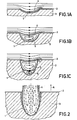
- Figure 1A is a diagrammatic cross-sectional view of the flow profile in a liquid etchant as it may occur at a given moment, for example, in the so-called spray-etching, in a shallow cavity 1 in a substrate 3 covered by means of an etching mask 2.
- the etching products 4 formed are taken along by the etchant flowing past the cavity 1.
- etching for example, in spray-etching, occurs rather rapidly.
- eddies 5 will form in the cavity 1 as is shown diagrammatically in the cross-sectional view of Figure 1B.
- the etching products 4 (shown dotted) formed at the wall of the cavity 1 are taken along only for a small part by the etchant flowing past the cavity 1 but for the greater part they can disappear from the cavity cavity 1 ( Figure 1B) only by diffusion. Consequently the etching rate decreases considerably.
- the etching rate is larges at the edges of the cavity 1 so that a strong undercutting starts to occur.
- the etching rate is lowest at the bottom of the cavity.
- the Figure 1C situation might occur in which two (5 and 6) or possibly more eddies are formed one over the other. In the Figure 1 C situation the etching products which are formed on the bottom of the cavity can only leave the cavity slowly.
- Figure 2 shows the situation in a method according to the invention.
- the arrow indicated by A denotes the direction of the acceleration of the artificial gravitational field, (as in cases 1 and 3).
- Figure 2 relates to a situation in which the density of the etchant in the proximity of the wall of the cavity 1 increases during etching. Under the influence of the artificial gravitational field the comparatively heavier liquid which is enriched in etching products 4 is drawn out of the cavity.
- the small arrows in this Figure and in the preceding Figures indicate the flow in the etchant.
- Figures 3A to 3C are diagrammatic cross-sectional views in side elevation (3A and 3C) and in plan view (3E), respectively, of an experimental device for etching with an etching liquid under the influence of an artificial gravitational field.
- an inner vessel 35 of etchant-resistant material for example, of polytetrafluoroethylene, is placed in the outer vessel 31.
- a holder 36 on which a substrate 37 to be etched is connected is present on the bottom of the inner vessel 35.
- An apertured etchant-resistant mask 38 is present on the substrate 37.
- the vessel 35 furthermore contains an etchant 39.
- the etchant 39 experiences an outwardly directed force (arrow A).
- the arrangement shown relates to a situation in which upon forming etching products the density of the etchant 39 increases at the wall of the apertures to be etched. Under the influence of the artificial gravitational field, etching products are removed from the apertures and cavities and are replaced by fresh etchant 39.
- a number of experiments were carried out in a device as is shown diagrammatically in Figures 3A - 3C.
- the vessel 35 had a capacity of 250 ml.
- the maximum speed of rotation was 30 rps. This provides an acceleration of the artificial gravitational field of 500 g at the location in the vessel where the samples to be etched are arranged.
- the samples were placed on top of ( Figure 3C) or below ( Figure 3A) a glass holder 36.
- the former case will hereinafter be referred to as a positive acceleration of the gravity and the second cases a negative acceleration.
- Slices of monocrystalline (100) oriented n-type GaAs having a thickness of 200 / um were etched.
- the slices were provided with a layer of Si0 2 obtained by pyrolysis in the form of a pattern having circular apertures with diameters ranging from 80 / um to 5000 ⁇ m.
- the slices were etched either with an etchant which has a preference for certain crystallographic directions in the crystal (A) or an etchant which etches at random (B).
- the etchant A consisted of:
- the etchant B consisted of:
- a 400 / um thick phosphorus bronze foil (composition 92% by weight of Cu, 7.6% by weight of Sn, 0.4% by weight P) was etched with an aqueous FeCl 3 solution having a density of 1.39 under the influence of artificial gravitational fields with acceleration from +500g to -25000g.
- the etching resist consisted of a layer of lacquer capable of withstanding the etchant.
- the apertures in the etching resist had diameters ranging from 100 to 5000 / um.
- the second value When one value is recorded in the Table it relates to a cavity having a diameter of 100 ⁇ m. When two values are recorded, the second value relates to a cavity having a diameter of 5000 / um. When the second value is 400 / um, the foil was etched through, this is not the etching depth which could have been reached with a foil thickness exceeding 400/um.
- the average etching rate with a given etching time at -350 g for various hole diameters is recorded in Table 3.
- the etching rate in a stationary etching bath is approximately 1 ⁇ m/minute for hole diameters ⁇ 100 ⁇ m.
- the etching rate was more than 40 / um/min with a hole diameter of 250 / um and 13 / um/min with a hole diameter of 100 / um, in both cases with an etching time of 15 min.
- FIG 4 shows diagrammatically a part of a practical embodiment for an etching device.
- the device comprises a closable vessel 41 having a lid 42 with which the vessel can be sealed in a liquid-tight manner.
- a holder 43 for example of a gauze of a metal which can withstand the etchant, is present in the vessel 41, the substrate to be etched can be provided by means of clamping members onto the gauze.
- the holder may comprise a number of surfaces, for example six, for connecting flat substrates.
- the vessel 41 is rotated by means of a driving device not shown. After providing the articles to be etched, the vessel, while stationary, can be filled with etchant to above the holder 43.
- etching is carried out essentially in a stationary etching bath. Under the influence of the artificial gravitational field, a local flow is caused during etching only in the cavities and apertures in the articles, as a result of density differences which occur in the etching liquid. These local flows ensure that etching products which, in case of prolonged stay in the cavities, would reduce the etching rate are removed out of the cavities and apertures.
Landscapes
- Chemical & Material Sciences (AREA)
- Metallurgy (AREA)
- Engineering & Computer Science (AREA)
- Materials Engineering (AREA)
- Mechanical Engineering (AREA)
- Chemical Kinetics & Catalysis (AREA)
- Organic Chemistry (AREA)
- General Chemical & Material Sciences (AREA)
- ing And Chemical Polishing (AREA)
- Materials For Medical Uses (AREA)
- Gas-Filled Discharge Tubes (AREA)
- Prostheses (AREA)
- Crystals, And After-Treatments Of Crystals (AREA)
- Particle Formation And Scattering Control In Inkjet Printers (AREA)
- Weting (AREA)
Priority Applications (1)
| Application Number | Priority Date | Filing Date | Title |
|---|---|---|---|
| AT83201569T ATE21530T1 (de) | 1982-11-08 | 1983-11-02 | Verfahren zum aetzen von hoehlen und oeffnungen in substraten. |
Applications Claiming Priority (2)
| Application Number | Priority Date | Filing Date | Title |
|---|---|---|---|
| NL8204307 | 1982-11-08 | ||
| NL8204307A NL8204307A (nl) | 1982-11-08 | 1982-11-08 | Werkwijze voor het etsen van holten en openingen in substraten en inrichting voor het uitvoeren van deze werkwijze. |
Publications (2)
| Publication Number | Publication Date |
|---|---|
| EP0108458A1 true EP0108458A1 (de) | 1984-05-16 |
| EP0108458B1 EP0108458B1 (de) | 1986-08-20 |
Family
ID=19840541
Family Applications (1)
| Application Number | Title | Priority Date | Filing Date |
|---|---|---|---|
| EP83201569A Expired EP0108458B1 (de) | 1982-11-08 | 1983-11-02 | Verfahren zum Ätzen von Höhlen und Öffnungen in Substraten |
Country Status (8)
| Country | Link |
|---|---|
| US (1) | US4448635A (de) |
| EP (1) | EP0108458B1 (de) |
| JP (1) | JPS5999724A (de) |
| AT (1) | ATE21530T1 (de) |
| AU (1) | AU557830B2 (de) |
| CA (1) | CA1230285A (de) |
| DE (1) | DE3365471D1 (de) |
| NL (1) | NL8204307A (de) |
Families Citing this family (11)
| Publication number | Priority date | Publication date | Assignee | Title |
|---|---|---|---|---|
| US4746397A (en) * | 1986-01-17 | 1988-05-24 | Matsushita Electric Industrial Co., Ltd. | Treatment method for plate-shaped substrate |
| US4927784A (en) * | 1987-05-01 | 1990-05-22 | Raytheon Company | Simultaneous formation of via hole and tube structures for GaAs monolithic microwave integrated circuits |
| US5120605A (en) * | 1988-09-23 | 1992-06-09 | Zuel Company, Inc. | Anti-reflective glass surface |
| US4944986A (en) * | 1988-09-23 | 1990-07-31 | Zuel Company | Anti-reflective glass surface |
| US5746876A (en) * | 1996-06-03 | 1998-05-05 | Taiwan Semiconductor Manufacturing Company, Ltd. | Safety sampler for hot acid in semiconductor manufacturing fab |
| US7857972B2 (en) * | 2003-09-05 | 2010-12-28 | Foret Plasma Labs, Llc | Apparatus for treating liquids with wave energy from an electrical arc |
| US9481584B2 (en) * | 2001-07-16 | 2016-11-01 | Foret Plasma Labs, Llc | System, method and apparatus for treating liquids with wave energy from plasma |
| US7422695B2 (en) * | 2003-09-05 | 2008-09-09 | Foret Plasma Labs, Llc | Treatment of fluids with wave energy from a carbon arc |
| US6929861B2 (en) | 2002-03-05 | 2005-08-16 | Zuel Company, Inc. | Anti-reflective glass surface with improved cleanability |
| JP5980012B2 (ja) * | 2012-06-27 | 2016-08-31 | キヤノン株式会社 | シリコンウェハの加工方法 |
| KR101665384B1 (ko) * | 2014-04-03 | 2016-10-12 | 한국지질자원연구원 | 중력계를 이용한 지하물질의 밀도변화 측정방법 |
Citations (2)
| Publication number | Priority date | Publication date | Assignee | Title |
|---|---|---|---|---|
| FR1523245A (fr) * | 1967-03-02 | 1968-05-03 | Corning Glass Works | Procédé de gravure à l'acide |
| FR2100151A5 (de) * | 1970-07-02 | 1972-03-17 | Ncr Co |
Family Cites Families (6)
| Publication number | Priority date | Publication date | Assignee | Title |
|---|---|---|---|---|
| DE143333C (de) * | ||||
| US2869266A (en) * | 1954-10-04 | 1959-01-20 | Turco Products Inc | Method for removing metal from the surface of a metal object |
| US2867929A (en) * | 1956-12-20 | 1959-01-13 | Gen Dynamics Corp | Method and apparatus for chemically boring metallic material |
| US3383255A (en) * | 1964-11-05 | 1968-05-14 | North American Rockwell | Planar etching of fused silica |
| US3730799A (en) * | 1971-07-07 | 1973-05-01 | Collins Radio Co | Method for metallic pattern definition |
| US4113549A (en) * | 1977-04-06 | 1978-09-12 | Chem-Tronics, Inc. | Chemical milling process |
-
1982
- 1982-11-08 NL NL8204307A patent/NL8204307A/nl not_active Application Discontinuation
-
1983
- 1983-02-04 US US06/463,761 patent/US4448635A/en not_active Expired - Fee Related
- 1983-11-02 AT AT83201569T patent/ATE21530T1/de not_active IP Right Cessation
- 1983-11-02 DE DE8383201569T patent/DE3365471D1/de not_active Expired
- 1983-11-02 EP EP83201569A patent/EP0108458B1/de not_active Expired
- 1983-11-03 CA CA000440408A patent/CA1230285A/en not_active Expired
- 1983-11-04 AU AU20979/83A patent/AU557830B2/en not_active Ceased
- 1983-11-08 JP JP58208448A patent/JPS5999724A/ja active Pending
Patent Citations (2)
| Publication number | Priority date | Publication date | Assignee | Title |
|---|---|---|---|---|
| FR1523245A (fr) * | 1967-03-02 | 1968-05-03 | Corning Glass Works | Procédé de gravure à l'acide |
| FR2100151A5 (de) * | 1970-07-02 | 1972-03-17 | Ncr Co |
Non-Patent Citations (2)
| Title |
|---|
| METALLOBERFLÄCHE, vol. 11, no. 8, August 1957, pages 253-254 * |
| THE REVIEW OF SCIENTIFIC INSTRUMENTS, vol. 35, no. 12, December 1964, pages 1726-1727 * |
Also Published As
| Publication number | Publication date |
|---|---|
| JPS5999724A (ja) | 1984-06-08 |
| ATE21530T1 (de) | 1986-09-15 |
| EP0108458B1 (de) | 1986-08-20 |
| DE3365471D1 (en) | 1986-09-25 |
| AU2097983A (en) | 1984-05-17 |
| AU557830B2 (en) | 1987-01-08 |
| US4448635A (en) | 1984-05-15 |
| NL8204307A (nl) | 1984-06-01 |
| CA1230285A (en) | 1987-12-15 |
Similar Documents
| Publication | Publication Date | Title |
|---|---|---|
| EP0108458B1 (de) | Verfahren zum Ätzen von Höhlen und Öffnungen in Substraten | |
| US5368634A (en) | Removing bubbles from small cavities | |
| EP0938597B1 (de) | Verfahren für das anisotrope ätzen von strukturen in leitende materialien | |
| US5217586A (en) | Electrochemical tool for uniform metal removal during electropolishing | |
| EP0550831B1 (de) | Elektrochemisches Mikrobearbeitungswerkzeug sowie Verfahren zum Aufbringen von Mustern mittels Schablonen auf dünne Metallfilms auf nichtleitende oder schlechtleitende Oberfläche | |
| US5340437A (en) | Process and apparatus for etching semiconductor wafers | |
| US4801380A (en) | Method of producing a silicon film with micropores | |
| JPH08112723A (ja) | 電解研磨法を利用した自動整列基板蝕刻方法 | |
| US3411999A (en) | Method of etching refractory metal based materials uniformly along a surface | |
| Basinski et al. | Copper single crystal PSB morphology between 4.2 and 350 K | |
| Kuiken et al. | Centrifugal etching: a promising new tool to achieve deep etching results | |
| Berlec | On the nature of dislocation etch pits in tungsten | |
| JPS55130839A (en) | Uniform etching method of article | |
| JPS56127791A (en) | Surface treatment of heat radiating body | |
| US3093503A (en) | Coated materials having an undercut substrate surface and method of preparing same | |
| JPS55154537A (en) | Method and apparatus for carrying molten metal | |
| Miller Jr et al. | An Electron Microscopic Study of the Formation of Oxide on Copper Single Crystals Immersed in an Aqueous Solution of Copper Sulfate | |
| US3730799A (en) | Method for metallic pattern definition | |
| Fukunaka et al. | Electrochemical interfacial phenomena under microgravity: Part I. Anodic dissolution of copper in drop shaft | |
| JPS5738910A (en) | Settling tank equipped with preventing device for sludge buoying | |
| JPS6455307A (en) | Production of acicular powder | |
| JP3304331B2 (ja) | 高いアスペクト比を有する微細構造物の製造方法 | |
| US4713145A (en) | Method of etching etch-resistant materials | |
| JPS62124744A (ja) | エツチング方法 | |
| SU1201938A1 (ru) | Способ изготовлени статора ртутного токосъемника |
Legal Events
| Date | Code | Title | Description |
|---|---|---|---|
| PUAI | Public reference made under article 153(3) epc to a published international application that has entered the european phase |
Free format text: ORIGINAL CODE: 0009012 |
|
| AK | Designated contracting states |
Designated state(s): AT BE CH DE FR GB IT LI SE |
|
| 17P | Request for examination filed |
Effective date: 19840726 |
|
| GRAA | (expected) grant |
Free format text: ORIGINAL CODE: 0009210 |
|
| AK | Designated contracting states |
Kind code of ref document: B1 Designated state(s): AT BE CH DE FR GB IT LI SE |
|
| REF | Corresponds to: |
Ref document number: 21530 Country of ref document: AT Date of ref document: 19860915 Kind code of ref document: T |
|
| REF | Corresponds to: |
Ref document number: 3365471 Country of ref document: DE Date of ref document: 19860925 |
|
| ITF | It: translation for a ep patent filed | ||
| ET | Fr: translation filed | ||
| PLBE | No opposition filed within time limit |
Free format text: ORIGINAL CODE: 0009261 |
|
| STAA | Information on the status of an ep patent application or granted ep patent |
Free format text: STATUS: NO OPPOSITION FILED WITHIN TIME LIMIT |
|
| 26N | No opposition filed | ||
| PGFP | Annual fee paid to national office [announced via postgrant information from national office to epo] |
Ref country code: BE Payment date: 19901107 Year of fee payment: 8 |
|
| PGFP | Annual fee paid to national office [announced via postgrant information from national office to epo] |
Ref country code: AT Payment date: 19901120 Year of fee payment: 8 |
|
| PGFP | Annual fee paid to national office [announced via postgrant information from national office to epo] |
Ref country code: SE Payment date: 19901127 Year of fee payment: 8 |
|
| ITTA | It: last paid annual fee | ||
| PGFP | Annual fee paid to national office [announced via postgrant information from national office to epo] |
Ref country code: CH Payment date: 19910222 Year of fee payment: 8 |
|
| PG25 | Lapsed in a contracting state [announced via postgrant information from national office to epo] |
Ref country code: AT Effective date: 19911102 |
|
| PG25 | Lapsed in a contracting state [announced via postgrant information from national office to epo] |
Ref country code: SE Effective date: 19911103 |
|
| PG25 | Lapsed in a contracting state [announced via postgrant information from national office to epo] |
Ref country code: LI Effective date: 19911130 Ref country code: CH Effective date: 19911130 Ref country code: BE Effective date: 19911130 |
|
| BERE | Be: lapsed |
Owner name: N.V. PHILIPS' GLOEILAMPENFABRIEKEN Effective date: 19911130 |
|
| REG | Reference to a national code |
Ref country code: CH Ref legal event code: PL |
|
| EUG | Se: european patent has lapsed |
Ref document number: 83201569.7 Effective date: 19920604 |
|
| REG | Reference to a national code |
Ref country code: FR Ref legal event code: CD |
|
| PGFP | Annual fee paid to national office [announced via postgrant information from national office to epo] |
Ref country code: GB Payment date: 19951101 Year of fee payment: 13 |
|
| PGFP | Annual fee paid to national office [announced via postgrant information from national office to epo] |
Ref country code: FR Payment date: 19951129 Year of fee payment: 13 |
|
| PGFP | Annual fee paid to national office [announced via postgrant information from national office to epo] |
Ref country code: DE Payment date: 19960125 Year of fee payment: 13 |
|
| PG25 | Lapsed in a contracting state [announced via postgrant information from national office to epo] |
Ref country code: GB Effective date: 19961102 |
|
| GBPC | Gb: european patent ceased through non-payment of renewal fee |
Effective date: 19961102 |
|
| PG25 | Lapsed in a contracting state [announced via postgrant information from national office to epo] |
Ref country code: FR Effective date: 19970731 |
|
| PG25 | Lapsed in a contracting state [announced via postgrant information from national office to epo] |
Ref country code: DE Effective date: 19970801 |
|
| REG | Reference to a national code |
Ref country code: FR Ref legal event code: ST |