EP0108655A1 - System zur Erkennung und Korrektur von Übertragungsfehlern in einer binären Nachricht mit einem Fehlererkennungs- und Korrekturcode des verzahnten zyklischen Reed-Solomon-Typs - Google Patents
System zur Erkennung und Korrektur von Übertragungsfehlern in einer binären Nachricht mit einem Fehlererkennungs- und Korrekturcode des verzahnten zyklischen Reed-Solomon-Typs Download PDFInfo
- Publication number
- EP0108655A1 EP0108655A1 EP83401791A EP83401791A EP0108655A1 EP 0108655 A1 EP0108655 A1 EP 0108655A1 EP 83401791 A EP83401791 A EP 83401791A EP 83401791 A EP83401791 A EP 83401791A EP 0108655 A1 EP0108655 A1 EP 0108655A1
- Authority
- EP
- European Patent Office
- Prior art keywords
- inputs
- message
- outputs
- errors
- code
- Prior art date
- Legal status (The legal status is an assumption and is not a legal conclusion. Google has not performed a legal analysis and makes no representation as to the accuracy of the status listed.)
- Granted
Links
- 238000012937 correction Methods 0.000 title claims abstract description 45
- 125000004122 cyclic group Chemical group 0.000 title claims abstract description 37
- 238000001514 detection method Methods 0.000 title claims abstract description 22
- 230000005540 biological transmission Effects 0.000 title claims abstract description 17
- 208000011580 syndromic disease Diseases 0.000 claims description 75
- 238000010200 validation analysis Methods 0.000 claims description 22
- 230000015654 memory Effects 0.000 claims description 18
- 239000011159 matrix material Substances 0.000 claims description 17
- 230000000873 masking effect Effects 0.000 claims description 2
- PWNAWOCHVWERAR-UHFFFAOYSA-N Flumetralin Chemical compound [O-][N+](=O)C=1C=C(C(F)(F)F)C=C([N+]([O-])=O)C=1N(CC)CC1=C(F)C=CC=C1Cl PWNAWOCHVWERAR-UHFFFAOYSA-N 0.000 claims 1
- 230000000712 assembly Effects 0.000 claims 1
- 238000000429 assembly Methods 0.000 claims 1
- 239000000463 material Substances 0.000 claims 1
- 238000000034 method Methods 0.000 description 21
- 230000008569 process Effects 0.000 description 11
- 238000004364 calculation method Methods 0.000 description 9
- 230000006870 function Effects 0.000 description 8
- 230000008901 benefit Effects 0.000 description 5
- 238000012360 testing method Methods 0.000 description 5
- 238000012545 processing Methods 0.000 description 4
- 239000000243 solution Substances 0.000 description 4
- 230000009897 systematic effect Effects 0.000 description 4
- 240000008042 Zea mays Species 0.000 description 3
- 230000002441 reversible effect Effects 0.000 description 3
- 241001644893 Entandrophragma utile Species 0.000 description 2
- 241000897276 Termes Species 0.000 description 2
- 230000009471 action Effects 0.000 description 2
- 230000006978 adaptation Effects 0.000 description 2
- 235000021183 entrée Nutrition 0.000 description 2
- 238000000605 extraction Methods 0.000 description 2
- 230000010365 information processing Effects 0.000 description 2
- 230000007246 mechanism Effects 0.000 description 2
- 230000011664 signaling Effects 0.000 description 2
- 101100135641 Caenorhabditis elegans par-3 gene Proteins 0.000 description 1
- 241000447437 Gerreidae Species 0.000 description 1
- 241000861223 Issus Species 0.000 description 1
- 241000863032 Trieres Species 0.000 description 1
- 230000008859 change Effects 0.000 description 1
- 230000000295 complement effect Effects 0.000 description 1
- 239000000470 constituent Substances 0.000 description 1
- 239000013256 coordination polymer Substances 0.000 description 1
- 238000000354 decomposition reaction Methods 0.000 description 1
- 230000007547 defect Effects 0.000 description 1
- 238000013461 design Methods 0.000 description 1
- 238000011161 development Methods 0.000 description 1
- 238000010586 diagram Methods 0.000 description 1
- 230000000694 effects Effects 0.000 description 1
- 239000007924 injection Substances 0.000 description 1
- 238000002347 injection Methods 0.000 description 1
- 101150006061 neur gene Proteins 0.000 description 1
- 230000003287 optical effect Effects 0.000 description 1
- 230000002093 peripheral effect Effects 0.000 description 1
- 230000001629 suppression Effects 0.000 description 1
- 238000012546 transfer Methods 0.000 description 1
- 230000001131 transforming effect Effects 0.000 description 1
Images


Classifications
-
- H—ELECTRICITY
- H03—ELECTRONIC CIRCUITRY
- H03M—CODING; DECODING; CODE CONVERSION IN GENERAL
- H03M13/00—Coding, decoding or code conversion, for error detection or error correction; Coding theory basic assumptions; Coding bounds; Error probability evaluation methods; Channel models; Simulation or testing of codes
- H03M13/03—Error detection or forward error correction by redundancy in data representation, i.e. code words containing more digits than the source words
- H03M13/05—Error detection or forward error correction by redundancy in data representation, i.e. code words containing more digits than the source words using block codes, i.e. a predetermined number of check bits joined to a predetermined number of information bits
- H03M13/13—Linear codes
- H03M13/15—Cyclic codes, i.e. cyclic shifts of codewords produce other codewords, e.g. codes defined by a generator polynomial, Bose-Chaudhuri-Hocquenghem [BCH] codes
-
- H—ELECTRICITY
- H03—ELECTRONIC CIRCUITRY
- H03M—CODING; DECODING; CODE CONVERSION IN GENERAL
- H03M13/00—Coding, decoding or code conversion, for error detection or error correction; Coding theory basic assumptions; Coding bounds; Error probability evaluation methods; Channel models; Simulation or testing of codes
- H03M13/27—Coding, decoding or code conversion, for error detection or error correction; Coding theory basic assumptions; Coding bounds; Error probability evaluation methods; Channel models; Simulation or testing of codes using interleaving techniques
Definitions
- the present invention relates to a system for detecting and correcting data transmission errors, using a self-correcting cyclic error code, of the interlaced Reed-Solomon type.
- the invention applies to the detection and correction of errors that may occur in data transmissions between different units of an information processing system. It more particularly applies to the detection and correction of data transmission errors between a central processing unit and peripheral units, such as very high density magnetic disks for example.
- the syndrome constitutes the summary of the configuration of errors, and it allows, within certain limits to find the error (s) and to correct them. But generally the aspect of the errors which occurred is not directly recognizable in the syndrome and the identification of the errors implies a more or less complex complementary treatment: decoding.
- the most commonly used codes for error detection are cyclic codes.
- the error detection operation consists in using, during reception (telecommunications) or reading (recording), a redundancy key concatenated to the message (systematic code) during its transmission.
- a redundancy key concatenated to the message (systematic code) during its transmission.
- a relatively short key a few bytes
- relatively long blocks a few thousand bytes.
- the cyclic code error detection process is simple (little hardware), effective (little redundancy) and powerful (possibility of recovering information at least when there are only random errors).
- the cyclic codes provide an answer to these objections, if the configuration of errors remains within reasonable limits, and provided that a key of sufficient length is added to the information block, it is possible to use this redundancy to correct the errors.
- the object of the invention is to provide a system for detecting and correcting data transmission errors, using a self-correcting cyclic code of errors, of the Reed-Solomon type, making it possible to remedy the drawbacks of known systems using cyclic codes.
- other types these drawbacks have been mentioned above and they essentially reside in the fact that no existing system makes it possible, at the same time, to detect and correct packets of errors, or to detect and correct multiple errors dispersed in a message coded.
- Systems that use a Hamming code for example, can detect a single or double error, but they only correct the single error.
- the subject of the invention is a system for coding, detecting and correcting errors in a binary message, using an interlaced Reed-Solomon type cyclic code, this message consisting of at least one useful sub-block of bytes having respectively the same number of binary data, the number of sub-blocks corresponding to the interleaving depth of the code, this system comprising a plurality of successive sets of deco registers .
- the first register of the first set of registers receiving, at initialization, one by one , the bytes of a message to be coded by the addition of a control key formed by bytes, obtained by concatenation with the useful bytes of the message, or receiving the bytes of a coded message containing a key and possibly having errors to detect and correct, a first addition "OR exclusive" type neur having outputs which are respectively connected to the inputs of the first register of the first set, inputs of this adder being respectively connected to the outputs of the last register of the last set of said plurality, other inputs of this adder receiving the data of each byte
- the first loopback circuit comprises another matrix for obtaining the coefficients of another polynomial generating the cyclic code of the message, of the interlaced Reed-Solomon type, the outputs of the matrices of this first loopback circuit being connected at the inputs of a first multiplexer whose outputs are connected to the inputs of the intermediate adders corresponding to this first loop-back circuit, the system further comprising a second multiplexer whose inputs are connected to the outputs of some of the successive Sils, the outputs of this second multiplexer being connected to the inputs of the adder corresponding to the last set, the choice of the outputs of some of the sets connected to the inputs of the second multiplexer depending on the code selected by a selection signal applied to this multiplexer.
- the matrices for obtaining the coefficients of the polynomial generating the cyclic code of the message include inputs which receive the data, and outputs which are connected by the corresponding loopback circuits, to the inputs of the intermediate adders, the outputs of these matrices being, either direct connections with the inputs of these matrices, or exits of doors of the "EXCLUSIVE OR" type receiving some of the data, the choice of the primitive polynomial (among 16 primitive polynomials), generator of the elements of the body of Galois, and the choice of a primitive element of this body minimizing the number of entrances to these doors.
- the system further comprises logic means for selecting the operating mode of the system comprising a first group of doors of type "AND", the number of these doors being equal to that of the data of each byte of a message and each of them having a first and a second input, the first inputs of the gates of this first group receiving respectively the data of each byte and the second inputs being able to receive a validation signal, either for coding or for the decoding of a message, the outputs of these gates being respectively connected to the inputs of the first "exclusive OR" adder, a second group of gates "AND", the number of these gates being equal to that of the data of each multiplet and each of them having a first and a second input, the first inputs of the doors of this second group being respectively connected to the outputs of the first adder and the second inputs being able to receive a validation signal, either for coding, either for the decoding of a message, the outputs of these gates being respectively connected to inputs for controlling the multiplication matrices of the data with the
- the system comprises detection means each having inputs which are respectively connected to the outputs of each first register of each set, for detecting the presence of a syndrome of possible errors in a decoded message, this syndrome being composed of all the syndromes of each sub-block.
- the system further comprises means for decoding the syndrome of possible errors linked to the means for detecting this syndrome, the decoding of the error syndrome being carried out in block by sub-block, this syndrome being the set of syndromes of the different sub-blocks.
- the means for decoding the error syndrome comprise an error configuration recording table connected to the means for detecting this syndrome, and indication means connected to outputs of the table to indicate the presence of errors in the entire data block and, among these errors, the existence of single errors or of multiple errors in each of the sub-blocks, these means of indication being connected to a counter receiving the clock pulses , so as to identify the positions of each byte which, in the message, is affected by errors, and so as to extract one by one from the last register of the last set, bytes representing respectively the contents of the errors in the bytes which, in the message, are affected by errors, the means of indication.
- tion comprising a logic making it possible to memorize the grouped single or double errors, in each of the sub-blocks.
- the position of each byte which, in the message, is affected by errors as well as the configurations of the errors in these bytes define an error table recorded in a memory.
- the system further comprises a buffer memory in which each block of data of a message to be decoded is recorded, the useful bytes of the message being accompanied by bytes constituting a key, so that when no error is detected during decoding, the useful bytes are transmitted directly to a user, and so that in the presence of errors detected during decoding, the error table makes it possible to correct by masking in the buffer memory bytes which in the message, present errors, before their transmission to a user.
- the means for detecting a syndrome of possible errors comprise, for each first register of each set, a gate of “OR” type, the inputs of which are connected to the outputs of this register and of which one output is connected to an entry in the error configuration registration table.
- Reed-Solomon code it is an algebraic, linear and cyclic code whose essential properties are as follows:
- the intertwined Reed-Solomon codes are of the form: ⁇ l + 3 representing a positive, negative or zero integer.
- the roots of G (x) are ai, ⁇ l + 1 , ⁇ l + 2 , ⁇ l + 3 , ⁇ l + 4 , if the logical distance d of the code is equal to 6.
- the development of G ( x) is then the following: with and a is the primitive element of a body of Ga - predetermined laws. We will show later how the coefficients A and B are obtained in the system of the invention.
- the key r is equal to d-l and therefore represents 5 bytes.
- the basic code is expressed symbolically in the form C (255, 250, 6) and the generating polynomial of this basic code is of the form:
- the code is interlaced.
- Interleaving is a decomposition of a block of information into a certain number of elementary sub-blocks, each of them having a length not exceeding the length of the code word of the chosen base code.
- An interlacing by 3 is shown below.
- the number of interleaving depths P is the number of elementary sub-blocks deduced from an initial information block.
- Interleaving makes it possible, for a basic code of given length, to protect a block of information, of greater length.
- the 750 bytes of useful data resulting from this interleaving make it possible to easily protect a block of 512 bytes.
- This interlaced code also makes it possible to operate on data organized on 8 eb words, in parallel.
- FIG. 1 schematically represents a system for coding, detecting and correcting errors in a binary message, using an interlaced Reed-Solomon type cyclic code.
- this message consists of at least one block of bytes which respectively have the same number of binary data.
- the system includes a shift register formed from a plurality of sets X, Y, Z, T, U, shift registers with parallel inputs and outputs. These registers are connected in series and are connected to a clock H which applies to their inputs CP shifts control pulses.
- the number of sets of registers is equal to the degree of the polynomial generating the cyclic code of the message to be processed. In the example considered, the number of sets of registers is equal to 5, while each set comprises three registers. This number corresponds to the interleaving depth of the cyclic code, of the Reed-Solomon type chosen.
- the inputs and outputs of the registers which have not been shown in detail are eight in number since the bytes are bytes. It is understood that for an interleaving depth by n, each set would have n registers.
- this system makes it possible, when it is desired to write a message on a magnetic disk of a magnetic device M, to add to this message bytes constituting a key. Useful bytes reach the magnetic device M directly via a BUS.
- this key comprises 15 bytes each formed by a byte (Q 0 , Q 1 ... Q 7 for example).
- D 0 , D 1 ... D 7 the binary elements of each byte of a message arriving on the DIN inputs of the system.
- These bytes can be those of a message to which one wishes to add a key before writing it on a magnetic disc, for example, but they can also be those of a coded message originating, for example, from a magnetic disc, message which one wishes to have. decode in order to find bytes which may contain errors, some of which can be corrected.
- the system also includes a first adder C l of the "exclusive OR" type which has outputs which are respectively connected to the inputs of the first register 1 of the first set X of registers. Since the bytes to be processed are bytes, the first adder CI has eight outputs.
- This adder includes inputs (8 inputs in the embodiment), which are re respectively linked to the outputs (8 outputs in the embodiment) of the last register n of the last set U of the registers.
- Other inputs of the adder C 1 receive the data D 8 , D 1 , D 2 ... D 7 of each byte of a message to be coded or decoded.
- the system also includes other intermediate adders C 2 , C 3 , C 4 ' C 5 , of the "exclusive OR" type.
- intermediate adders are respectively connected by inputs and outputs, with the outputs and inputs of the successive sets X, Y, Z, T, U, of shift registers.
- Other inputs of these intermediate adders (8 inputs in the embodiment) are respectively connected by loopback circuits R 1 , R 2 , with the inputs of the first register 1 of the first set X.
- Each of the loopback circuits R 1 , R 2 comprises matrices A, B which will be described later in detail and which make it possible to multiply the data of each byte of a message arriving at the inputs of the system, by the coefficients of the generator polynomial of the cyclic code of the message, of Reed-Solomon type, described above. These coefficients are obtained from the primitive element of a predetermined Galois body. In the embodiment considered, these matrices are square matrices having eight inputs and eight outputs. These matrices apply the binary values of the coefficients of the generator polynomial to the inputs of the intermediate adders C 2 , C 3 , C 4 , C 5.
- the system further comprises logic means for selecting the operating modes of the system.
- These logic means comprise a first group P 1 of "AND" type doors. The number of these doors is equal to that of the data of each byte of a message received by the system. These doors are not re shown in detail in the figure; these are ET type doors, well known in the state of the art, which each have two inputs and one output.
- the first DIN inputs of these gates respectively receive the data D 0 , D1 ... D7 of each byte of a message to be coded or decoded, and the second inputs of these gates receive a validation signal VIN, ie to validate the coding, or to validate the detection of errors in a message.
- the outputs of these doors are respectively connected to the inputs of the first adder C l , of the "exclusive OR" type.
- the logic means for selecting the operating mode of the system also includes a second group P 2 of AND type doors. These doors which are not shown in detail in the figure are doors with two entrances and one exit. Their number is equal to that of the data of each byte of a message, that is to say eight in the embodiment considered.
- the first inputs of the doors of this second group P 2 are respectively connected to the outputs of the first adder C 1 , and the second inputs of these doors are capable of receiving a validation signal VCOEFF; this validation signal is used either for coding or for decoding a message, so as to validate the multiplications to be carried out using the multiplication matrices A and B, contained in the loopback circuits R 1 , R 2 .
- the outputs of the doors of the second group P 2 are respectively connected to inputs for controlling the matrices B.
- the logic means also include a third group P 3 of AND gates whose number is equal to that of the data of each byte of a message to code or decode (8 in the example considered).
- Each of these doors has a first and a second entry.
- the first inputs of the doors of group P 3 are respectively connected to the outputs of the last register of the last set U.
- the first inputs of these doors receive a loopback validation signal VREB, for coding or decoding a message.
- the logical means for selecting the operating mode of the system comprise an output door P 4 with three states. This door has inputs (8 inputs in the example considered) which are respectively connected to the outputs of the last register
- n of the last set U This door, well known in the state of the art, is not shown in detail in the figure. It provides on DOUT outputs, that is to say bytes of a key to be added to a message for coding it (these bytes being bytes (Q 0 , Q 1 ... Q 7 ) in the example considered) , it possibly provides bytes resulting from an error syndrome, when decoding a message. It has a command input capable of receiving a validation signal EM when it is desired, under certain conditions which will be described later in detail, to extract the byte contained in the register
- the gate P 4 is controlled by a circuit P5 using combinatorial logic.
- This circuit provides a validation signal VOUT which depends on the binary value of the signals REP, a 0 , a l , a 2 , which it receives.
- the signal REP is in particular a reset signal which is also supplied to the registers of the sets and a specific logic circuit P 6 for resetting the last register of the set U, this latter register in fact depends on the depth of interlacing.
- the signals a 0 , a l , a 2 allow to select the operating modes of the device, which will be described later. In fact, these operating modes can be as follows: Calculation of the syndrome or of the key (when the content of all the sets of active registers has been emptied), emptying of the registers with reset, emptying of the registers with conservation of their content (when the content of all the sets of active registers has been emptied), decoding of the error syndrome, change of the registers.
- This circuit also receives the signal MR resetting all the sets of the register to zero (used during initialization), as well as binary signals S 0 , S 1 which make it possible to define the depth P of interleaving chosen, for the code considered.
- This depth can have, in the example of embodiment described, one of the values 1, 2, 3, or 5.
- control signals such as VREB, VCOEFF, VIN, MR , REP, S 0 ' S 1 , a 0 , a 1 , a 2 are supplied for example by a processor which supplies or receives the data, or by a sequencer controlled by this processor.
- the system also includes detection means D 1 , D2, D3, D 4 each having inputs which are respectively connected to the outputs of the first register of each of the sets of registers X, Y, Z, T, Q.
- detection means D 1 , D2, D3, D 4 each having inputs which are respectively connected to the outputs of the first register of each of the sets of registers X, Y, Z, T, Q.
- the outputs of the doors D 1 , D 2 , D 3 , D 4 are respectively connected to the inputs of decoding means D of the possible error syndrome.
- These decoding means comprise a table EC for recording the configuration of errors, the inputs of which are connected to the outputs of the detection means D l , D 2 , D 3 , D 4 , D5.
- the decoding means also comprise means of indication I, connected to outputs of the table E to indicate by a signal ER, the presence of errors in a decoded message.
- These indication means also make it possible, respectively to indicate by signals ES and EM, the presence of single errors or of multiple errors among the errors detected in the message.
- These means of indication are connected by their outputs to a counter C which also receives the pulses of the clock H.
- the indication means (I) consist of a combinational and sequential logic which, in the case of an interleaving by 3 for example, makes it possible to indicate the presence of a single or double error grouped in each sub-block d 'information.
- the presence of an error throughout the block is indicated by the signal ER; the decoding of the errors is done sub-block by sub-block; if there is a simple grouped error, it is then indicated by the signal ES, when the error is double and grouped it is indicated by the signal EM.
- the binary signals S 0 , S 1 applied to the inputs of the indication means 1 make it possible to define the chosen interleaving depth.
- the counter (C) allows, as will be seen below in detail, to locate the positions of each byte which, in the message is affected by errors. It allows you to control the offsets so to extract one by one from the last register n of the last set U, bytes representing respectively the configurations of the errors in them. bytes which, in the message, are affected by errors. The position of each byte which, in the message is affected by errors, as well as the configurations of the errors in these bytes define a table of errors, recorded in a memory TE.
- the system also comprises a buffer memory MT in which each data block of a message to be decoded originating from a magnetic disk M is recorded for example. In this buffer, the useful bytes of the message are separated from the bytes constituting the key.
- the useful bytes are transmitted directly to a user by UT outputs, while in the presence of errors detected during decoding, the TE error table makes it possible to correct the bytes which, in the MT buffer, have errors. As a result, the message transmitted to the user no longer contains errors.
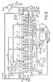
- FIG. 2 schematically represents another embodiment of the system according to the invention.
- the same elements have the same references in this figure and in Figure 1.
- the system operates in a similar manner in the two embodiments; however, in the embodiment shown in Figure 2, the system allows you to choose between two cyclic Reed-Solomon codes of the message. This choice results from the presence of the multiplexers MX1 and MX2, as well as from the presence of a matrix E for obtaining the coefficients of another polynomial generating the cyclic code of the message.
- the inputs of the first multiplexer MXl are connected to the outputs of the matrix A giving some of the coeffi cients of the generator polynomial of a first code defined above, and at the outputs of the matrix E giving the coefficients of the other generator polynome chosen.
- the second mutiplexer MX2 has inputs which are connected on the one hand to the outputs of the last register of the second set Y and, on the other hand, to the outputs of the last register of the penultimate set T.
- the outputs of this second multiplexer are connected to the inputs of the adder C 5 , which in the first embodiment were connected to the outputs of the assembly T.
- Each of the multiplexers MXl, MX2 receives a signal SC which makes it possible to select the chosen code.
- This signal is also applied to the error configuration recording table EC to differentiate the different error configurations that may result from each of the codes. It therefore allows, thanks to the multiplexers, either to choose the basic code (255, 250, 6), already described, involving the matrices A and B through the loopback circuits R 1 , R 21 or to choose a new code making intervene only the matrix E, through the circuit R 1 .
- the new base code is: C '(255, 252, 4).
- the chosen code is a degenerate code whose polynomial generator G '(x) is of the form:
- a is a primitive element of a Galois body CG (2 8 ); this polynomial can be written in the form of a symmetric polynomial:
- the matrix E represented in the figure makes it possible to obtain the coefficient of this new generator polynomial, which provides a redundancy code 3 (3 bytes), while the code obtained from the matrices A and B was redundancy 5 (5 bytes ).
- the multiplexers MX1, MX2 by the command SC thus make it possible to inhibit the third and fourth sets Z, T of registers whose contents are set to zero.
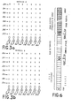
- FIGS. 3a and 3b schematically represent the multiplication matrices A and B making it possible to obtain the coefficients of the polynomial generator of the cyclic code, of Reed-Solomon type, chosen.
- the data D 0 is transmitted directly to an input of the adders C 2 and C 5 by direct link, without the need to use a gate A 0 .
- the matrix E used in the second embodiment of the system has not been shown in detail; the same considerations as those which led to obtaining the matrices A and B, allows try to reach the matrix E.
- the registers are reset to zero by the signals REP and MR.
- the content of the registers is not only shifted with each clock pulse, but is modified as a result of the action of the loopbacks.
- the general principle is that after a certain number of clock pulses the configuration of errors appears in the registers. This last condition tion is detected by the ES and EM signals, as will be seen later in detail.
- this mode is used to perform certain operations such as loading into the registers of a certain configuration for the purpose of decoding.
- step a As the initialization (step a) consists in zeroing all the registers of the system everything happens as if we had injected 238 null bytes (the registers remain at zero since the loopback line is permanently at zero) followed by the 512 useful bytes. This reasoning explains the very simple mechanism of truncation that we will find in the reading phase.
- the only imperative condition is that the length (useful data + key) of the real code word is less than or equal to the code period.
- the k bytes of useful data and the r bytes of key will form a code word which, during the reading phase, will be read in one go, without breaking the clock phase when l 'we will cross the border between useful data and key.
- Reading a message and detecting errors in it consist in generating the error syndrome, from the data read on a disk for example and in testing this syndrome.
- the error syndrome is zero, it can be assumed that there is no error, and validate the information temporarily stored in the buffer memory MT.
- this data is also loaded into the buffer memory MT.
- the syndrome decoding operation is linear and reversible; it consists, within the limit of the power of the code, in replacing this syndrome with information that can be directly used on each error (location and content of the errors). All the information actually exists in the syndrome, but it is encrypted and is not directly recognizable to allow correction of errors, or even to decide if one is able to do it.
- the decoding of the syndrome is, in known systems and in the case of any multiple errors, a complex operation using mathematical algorithms which are difficult to describe in this document. Furthermore, the execution time of these algorithms can become very large for errors of high multiplicity.
- the system of the invention allows an elementary decoding of the single errors and of the multiple errors grouped by means of a scan, in one passage of the period of the code. This process leads to sending to the system, under the control of a counter, the desired number of clock pulses and to come and test, at each step, the signal ES for single errors and the signal EM for multiple errors grouped , on the outputs of the indication means I.
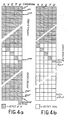
- Figures 4a and 4b show what happens in the case of a simple error.
- the process of sequential scanning of the contents of the registers X, Y, Z, T has been shown when an error syndrome has been obtained in the form of a table with 5 columns and 256 rows.
- Each column corresponds in order to each of the 5 sets X, Y, Z, T or U of the shift register (X, Y, Z , T , U).
- the lines correspond, in order, to the successive states of the register after each step caused by the sending of a clock pulse loge H.
- Each box represents the content of a set at a given time, that is to say that it represents a byte.
- the first line of the table schematically represents the content of the shift register (X, Y, Z, T, U) immediately at the end of reading and before starting the decoding process. It's error syndrome.
- the content of the register changes by the simultaneous action of a shift of a position to the right, and re-injections by intermediate loopbacks.
- the latter cause the information to be not only shifted, but modified with each clock pulse.
- we will have 5 non-zero bytes (we may encounter a single zero byte from time to time), which contain information on errors, but always in encrypted form.
- the last register n is reset to zero by a signal RAZn transmitted by a gate P 5 of type ET which receives the signal MR and a signal REP when an error syndrome is obtained.
- the period of the code will have been scanned once and only once.
- a 255th clock pulse will restore (in 256th line), the initial content of the register, i.e. the syndrome.
- the last active register of the last set U which will be reset.
- the two inactive registers in each set are at zero.
- the command to reset the last active register of the last set U to zero depends on the binary values of the signals S 0 and S 1 which define the interleaving depth.
- the ES signal may never go up. It just means that we didn't have a simple error.
- the sequential process operates at the start as described above. That is to say that encrypted information evolves in the register. Suddenly, three zero bytes appear among the four sets Y, Z, T and U. In the example, the zero bytes will be Y, T and U.
- the non-zero byte contained in X is the content E 1 of the first error
- the non-zero byte contained in Z is the content E 2 of the second error.
- the double error can be indicated by the signal EM obtained by the majority function (2 among 5) on the variables x, y, z, t and u or better, by the majority function composed: (u, x, y, z, t being the contents of the first registers of the sets U, X, Y, Z, T).
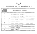
- the error table can contain between 1 and 6 decoded errors, according to the table in figure 7. Examination of the modulo 3 congruences between the addresses of the different errors will allow to know exactly the case of figure in which one is and if this case is valid.
- TE table of errors
- Raw data are also available in the buffer memory MT.
Landscapes
- Physics & Mathematics (AREA)
- Probability & Statistics with Applications (AREA)
- Engineering & Computer Science (AREA)
- Theoretical Computer Science (AREA)
- Algebra (AREA)
- General Physics & Mathematics (AREA)
- Mathematical Physics (AREA)
- Pure & Applied Mathematics (AREA)
- Error Detection And Correction (AREA)
- Detection And Correction Of Errors (AREA)
Applications Claiming Priority (2)
| Application Number | Priority Date | Filing Date | Title |
|---|---|---|---|
| FR8215403 | 1982-09-13 | ||
| FR8215403A FR2533091A1 (fr) | 1982-09-13 | 1982-09-13 | Systeme de detection et de correction d'erreurs de transmission d'un message binaire utilisant un code cyclique detecteur et correcteur d'erreurs de type reed-solomon entrelace |
Publications (2)
| Publication Number | Publication Date |
|---|---|
| EP0108655A1 true EP0108655A1 (de) | 1984-05-16 |
| EP0108655B1 EP0108655B1 (de) | 1986-12-03 |
Family
ID=9277380
Family Applications (1)
| Application Number | Title | Priority Date | Filing Date |
|---|---|---|---|
| EP83401791A Expired EP0108655B1 (de) | 1982-09-13 | 1983-09-13 | System zur Erkennung und Korrektur von Übertragungsfehlern in einer binären Nachricht mit einem Fehlererkennungs- und Korrekturcode des verzahnten zyklischen Reed-Solomon-Typs |
Country Status (5)
| Country | Link |
|---|---|
| US (1) | US4566105A (de) |
| EP (1) | EP0108655B1 (de) |
| JP (1) | JPS59131238A (de) |
| DE (1) | DE3368134D1 (de) |
| FR (1) | FR2533091A1 (de) |
Cited By (5)
| Publication number | Priority date | Publication date | Assignee | Title |
|---|---|---|---|---|
| GB2149540A (en) * | 1983-11-10 | 1985-06-12 | Gen Signal Corp | Vital processor |
| FR2624676A1 (fr) * | 1987-12-11 | 1989-06-16 | Trt Telecom Radio Electr | Dispositif de codage et de decodage de codes reed-solomon |
| EP0471380A1 (de) * | 1990-08-17 | 1992-02-19 | Hitachi, Ltd. | ATM-Vermittlungsschaltung |
| US6507584B1 (en) | 1997-11-20 | 2003-01-14 | Hitachi, Ltd. | ATM switch |
| EP1420373A1 (de) * | 2002-11-18 | 2004-05-19 | France Telecom | Kodeskontroll für virtuelle vorausbezahlte Karte |
Families Citing this family (31)
| Publication number | Priority date | Publication date | Assignee | Title |
|---|---|---|---|---|
| US5007018A (en) * | 1983-11-10 | 1991-04-09 | General Signal Corp. | Vital processor implemented with non-vital hardware |
| FR2565002B1 (fr) * | 1984-05-25 | 1986-08-22 | Bull Sa | Processeur de detection et de correction d'erreurs selon un code produit reed solomon entrelace |
| US4649541A (en) * | 1984-11-21 | 1987-03-10 | The United States Of America As Represented By The Administrator Of The National Aeronautics And Space Administration | Reed-Solomon decoder |
| US4856003A (en) * | 1987-05-07 | 1989-08-08 | Digital Equipment Corporation | Error correction code encoder |
| US4843607A (en) * | 1987-12-17 | 1989-06-27 | Cyclotomics, Inc. | Multiple error trapping |
| EP0341851A3 (de) * | 1988-05-12 | 1991-06-12 | Digital Equipment Corporation | Verfahren und Gerät für verschachtelte Kodierung |
| US4916702A (en) * | 1988-06-17 | 1990-04-10 | Cyclotomics, Inc. | Elongated burst trapping |
| US5241546A (en) * | 1991-02-01 | 1993-08-31 | Quantum Corporation | On-the-fly error correction with embedded digital controller |
| US5280488A (en) * | 1990-11-08 | 1994-01-18 | Neal Glover | Reed-Solomon code system employing k-bit serial techniques for encoding and burst error trapping |
| US5414719A (en) * | 1992-04-24 | 1995-05-09 | Sharp Kabushiki Kaisha | Operating circuit for galois field |
| JPH0787090A (ja) * | 1993-06-30 | 1995-03-31 | Toyo Commun Equip Co Ltd | 巡回符号検出方法及び装置 |
| EP0700182B1 (de) * | 1994-08-31 | 2001-01-03 | Nec Corporation | Gerät zur Dekodierung mit Fehlerkorrektur in digitalen Datenübertragungssystemen |
| US5657331A (en) * | 1995-03-13 | 1997-08-12 | Samsung Electronics Co., Ltd. | Method and apparatus for the generation of simple burst error correcting cyclic codes for use in burst error trapping decoders |
| US5781133A (en) * | 1996-08-05 | 1998-07-14 | Seagate Technology, Inc. | Method and apparatus for implementing run length limited codes |
| US5983383A (en) * | 1997-01-17 | 1999-11-09 | Qualcom Incorporated | Method and apparatus for transmitting and receiving concatenated code data |
| US6615387B1 (en) * | 1998-09-22 | 2003-09-02 | Seagate Technology Llc | Method and apparatus for error detection |
| FR2785741B1 (fr) * | 1998-11-09 | 2001-01-26 | Canon Kk | Dispositif et procede de codage et d'entrelacement pour des turbocodes series ou hybrides |
| JP3485075B2 (ja) * | 2000-07-19 | 2004-01-13 | 日本電気株式会社 | 復号回路及びその復号方法 |
| US7028245B2 (en) * | 2001-08-21 | 2006-04-11 | Equator Technologies, Inc. | Even-load software Reed-Solomon decoder |
| FR2839222B1 (fr) * | 2002-04-26 | 2004-09-10 | St Microelectronics Sa | Procede et circuit d'entrelacement de donnnees numeriques pour la reduction d'erreurs de transmission |
| EP1460765A1 (de) * | 2003-03-19 | 2004-09-22 | STMicroelectronics S.r.l. | Fehlerkorrekturmethode für als Symbolsequenz codierte digitale Daten |
| US7155656B1 (en) * | 2003-05-01 | 2006-12-26 | Hellosoft Inc. | Method and system for decoding of binary shortened cyclic code |
| US7320101B1 (en) * | 2003-08-19 | 2008-01-15 | Altera Corporation | Fast parallel calculation of cyclic redundancy checks |
| US7613991B1 (en) | 2003-08-19 | 2009-11-03 | Altera Corporation | Method and apparatus for concurrent calculation of cyclic redundancy checks |
| US8832523B2 (en) * | 2006-03-03 | 2014-09-09 | Ternarylogic Llc | Multi-state symbol error correction in matrix based codes |
| US9203436B2 (en) * | 2006-07-12 | 2015-12-01 | Ternarylogic Llc | Error correction in multi-valued (p,k) codes |
| US20080148132A1 (en) * | 2006-10-26 | 2008-06-19 | Mavila Rajith K | Error detection and correction scheme for multi-level cell NAND flash |
| US9075111B2 (en) * | 2013-10-07 | 2015-07-07 | King Fahd University Of Petroleum And Minerals | Generalized modular redundancy fault tolerance method for combinational circuits |
| DE102018113475A1 (de) * | 2018-06-06 | 2019-12-12 | Infineon Technologies Ag | Rechenwerk zum rechnen mit maskierten daten |
| CN114115806B (zh) * | 2021-11-29 | 2025-06-13 | 天津光电通信技术有限公司 | 一种数据流字节滑动异或计算的方法 |
| US12212338B1 (en) * | 2023-07-26 | 2025-01-28 | Winbond Electronics Corp. | Syndrome decoder circuit |
Citations (3)
| Publication number | Priority date | Publication date | Assignee | Title |
|---|---|---|---|---|
| US4242752A (en) * | 1977-12-30 | 1980-12-30 | Siemens Aktiengesellschaft | Circuit arrangement for coding or decoding of binary data |
| WO1982002103A1 (en) * | 1980-12-11 | 1982-06-24 | Elwyn R Berlekamp | Bit serial encoder |
| US4340964A (en) * | 1979-06-27 | 1982-07-20 | Siemens Aktiengesellschaft | Method and an arrangement for automatic access optimization in random access memories |
Family Cites Families (4)
| Publication number | Priority date | Publication date | Assignee | Title |
|---|---|---|---|---|
| US3562711A (en) * | 1968-07-16 | 1971-02-09 | Ibm | Apparatus for detecting circuit malfunctions |
| JPS5425106A (en) * | 1977-07-27 | 1979-02-24 | Nec Corp | Correcting device for double error |
| JPS54125901A (en) * | 1978-03-24 | 1979-09-29 | Sony Corp | Error correction system |
| DE3122381A1 (de) * | 1981-06-05 | 1982-12-23 | Ibm Deutschland Gmbh, 7000 Stuttgart | Verfahren und einrichtung zur erzeugung von pruefbits zur sicherung eines datenwortes |
-
1982
- 1982-09-13 FR FR8215403A patent/FR2533091A1/fr active Granted
-
1983
- 1983-09-08 JP JP58165843A patent/JPS59131238A/ja active Granted
- 1983-09-13 DE DE8383401791T patent/DE3368134D1/de not_active Expired
- 1983-09-13 US US06/531,680 patent/US4566105A/en not_active Expired - Fee Related
- 1983-09-13 EP EP83401791A patent/EP0108655B1/de not_active Expired
Patent Citations (3)
| Publication number | Priority date | Publication date | Assignee | Title |
|---|---|---|---|---|
| US4242752A (en) * | 1977-12-30 | 1980-12-30 | Siemens Aktiengesellschaft | Circuit arrangement for coding or decoding of binary data |
| US4340964A (en) * | 1979-06-27 | 1982-07-20 | Siemens Aktiengesellschaft | Method and an arrangement for automatic access optimization in random access memories |
| WO1982002103A1 (en) * | 1980-12-11 | 1982-06-24 | Elwyn R Berlekamp | Bit serial encoder |
Non-Patent Citations (1)
| Title |
|---|
| IBM TECHNICAL DISCLOSURE BULLETIN, vol. 18, no. 8, janvier 1976, pages 2426-2427, New York, US * |
Cited By (9)
| Publication number | Priority date | Publication date | Assignee | Title |
|---|---|---|---|---|
| GB2149540A (en) * | 1983-11-10 | 1985-06-12 | Gen Signal Corp | Vital processor |
| GB2169114A (en) * | 1983-11-10 | 1986-07-02 | Gen Signal Corp | Vital processor v |
| US4831521A (en) * | 1983-11-10 | 1989-05-16 | General Signal Corporation | Vital processor implemented with non-vital hardware |
| FR2624676A1 (fr) * | 1987-12-11 | 1989-06-16 | Trt Telecom Radio Electr | Dispositif de codage et de decodage de codes reed-solomon |
| EP0471380A1 (de) * | 1990-08-17 | 1992-02-19 | Hitachi, Ltd. | ATM-Vermittlungsschaltung |
| US6067654A (en) * | 1990-08-17 | 2000-05-23 | Hitachi, Ltd. | ATM switch and control method thereof |
| US6507584B1 (en) | 1997-11-20 | 2003-01-14 | Hitachi, Ltd. | ATM switch |
| EP1420373A1 (de) * | 2002-11-18 | 2004-05-19 | France Telecom | Kodeskontroll für virtuelle vorausbezahlte Karte |
| FR2847368A1 (fr) * | 2002-11-18 | 2004-05-21 | France Telecom | Controle de code de carte pre-payee virtuelle |
Also Published As
| Publication number | Publication date |
|---|---|
| JPH0126209B2 (de) | 1989-05-23 |
| DE3368134D1 (en) | 1987-01-15 |
| EP0108655B1 (de) | 1986-12-03 |
| JPS59131238A (ja) | 1984-07-28 |
| FR2533091B1 (de) | 1985-02-01 |
| FR2533091A1 (fr) | 1984-03-16 |
| US4566105A (en) | 1986-01-21 |
Similar Documents
| Publication | Publication Date | Title |
|---|---|---|
| EP0108655B1 (de) | System zur Erkennung und Korrektur von Übertragungsfehlern in einer binären Nachricht mit einem Fehlererkennungs- und Korrekturcode des verzahnten zyklischen Reed-Solomon-Typs | |
| FR2860360A1 (fr) | Dispositif de codage /decodage utilisant un codeur/decodeur de reed-solomon | |
| EP0436251A2 (de) | System zur Kodierung/Dekodierung von digitalen Signalen zur Übertragung und/oder Speicherung | |
| FR2785743A1 (fr) | Dispositif et procede d'adaptation des turbocodeurs et des decodeurs associes a des sequences de longueur variable | |
| FR2815199A1 (fr) | Procedes de turbocodage circulaire de grande distance minimale, et systemes pour leur mise en oeuvre | |
| CH653457A5 (fr) | Procede de correction d'erreurs dans des signaux de donnees digitales. | |
| FR2849514A1 (fr) | Code de geometrie algebrique adapte aux erreurs en rafale | |
| FR2790621A1 (fr) | Dispositif et procede d'entrelacement pour turbocodage et turbodecodage | |
| EP0204635B1 (de) | Verfahren zur Übertragung von digitaler Information in Wörterblöcken | |
| FR2540690A1 (fr) | Verificateur de codeur | |
| FR2673341A1 (fr) | Agencement de circuit pour detecter et corriger des defauts dans des mots de donnees. | |
| EP2394366A1 (de) | Fehlerkorrektur-codierungsverfahren mit totalparitätbit und verfahren zum detektieren mehrerer fehler | |
| EP0204612B1 (de) | Verfahren zur Datenübertragung mit Möglichkeit zur Korrektur von Fehlerpaketen und Kodierungs- und Dekodierungsanordnung zur Durchführung dieses Verfahrens | |
| FR2785744A1 (fr) | Procede et dispositif de codage de sequences de donnees, procede et dispositif de decodage associes | |
| EP1300952A1 (de) | Hocheffizienter Fehlerdetektion - und/oder korrekturcode | |
| BE743592A (de) | ||
| FR2720528A1 (fr) | Décodeur de correction d'erreur. | |
| FR2866998A1 (fr) | Decodage et correction d'erreurs pour codes de geometrie algebrique | |
| EP1076933B1 (de) | Vorrichtung zur berichtigung von fehlern und optischer plattenspieler, der eine solche vorrichtung einschliesst | |
| EP2833555B1 (de) | Verbessertes Verfahren zur Decodierung eines Korrekturcodes mit Message Passing, insbesondere für die Decodierung von Low-Density-Parity-Check-Codes oder Turbo-Codes | |
| FR2863794A1 (fr) | Procedes et dispositifs de localisation d'erreurs pour les codes de geometrie algebrique | |
| FR2900294A1 (fr) | Chargement de la memoire d'entree d'un decodeur ldpc avec des donnees a decoder | |
| FR2867925A1 (fr) | Codage de canal adapte aux erreurs rafale | |
| FR2773284A1 (fr) | Circuit de calcul de polynome de syndrome et un circuit de decodage reed-solomon | |
| FR2858141A1 (fr) | Codage d'informations par codes de reed-solomon raccourcis |
Legal Events
| Date | Code | Title | Description |
|---|---|---|---|
| PUAI | Public reference made under article 153(3) epc to a published international application that has entered the european phase |
Free format text: ORIGINAL CODE: 0009012 |
|
| AK | Designated contracting states |
Designated state(s): DE FR GB IT NL |
|
| 17P | Request for examination filed |
Effective date: 19840405 |
|
| ITF | It: translation for a ep patent filed | ||
| GRAA | (expected) grant |
Free format text: ORIGINAL CODE: 0009210 |
|
| AK | Designated contracting states |
Kind code of ref document: B1 Designated state(s): DE FR GB IT NL |
|
| REF | Corresponds to: |
Ref document number: 3368134 Country of ref document: DE Date of ref document: 19870115 |
|
| PLBE | No opposition filed within time limit |
Free format text: ORIGINAL CODE: 0009261 |
|
| STAA | Information on the status of an ep patent application or granted ep patent |
Free format text: STATUS: NO OPPOSITION FILED WITHIN TIME LIMIT |
|
| 26N | No opposition filed | ||
| ITTA | It: last paid annual fee | ||
| PGFP | Annual fee paid to national office [announced via postgrant information from national office to epo] |
Ref country code: FR Payment date: 19960826 Year of fee payment: 14 |
|
| PGFP | Annual fee paid to national office [announced via postgrant information from national office to epo] |
Ref country code: GB Payment date: 19960830 Year of fee payment: 14 |
|
| PGFP | Annual fee paid to national office [announced via postgrant information from national office to epo] |
Ref country code: NL Payment date: 19960930 Year of fee payment: 14 |
|
| PGFP | Annual fee paid to national office [announced via postgrant information from national office to epo] |
Ref country code: DE Payment date: 19961024 Year of fee payment: 14 |
|
| PG25 | Lapsed in a contracting state [announced via postgrant information from national office to epo] |
Ref country code: GB Free format text: LAPSE BECAUSE OF NON-PAYMENT OF DUE FEES Effective date: 19970913 |
|
| PG25 | Lapsed in a contracting state [announced via postgrant information from national office to epo] |
Ref country code: FR Free format text: THE PATENT HAS BEEN ANNULLED BY A DECISION OF A NATIONAL AUTHORITY Effective date: 19970930 |
|
| PG25 | Lapsed in a contracting state [announced via postgrant information from national office to epo] |
Ref country code: NL Free format text: LAPSE BECAUSE OF NON-PAYMENT OF DUE FEES Effective date: 19980401 |
|
| GBPC | Gb: european patent ceased through non-payment of renewal fee |
Effective date: 19970913 |
|
| NLV4 | Nl: lapsed or anulled due to non-payment of the annual fee |
Effective date: 19980401 |
|
| PG25 | Lapsed in a contracting state [announced via postgrant information from national office to epo] |
Ref country code: DE Free format text: LAPSE BECAUSE OF NON-PAYMENT OF DUE FEES Effective date: 19980603 |
|
| REG | Reference to a national code |
Ref country code: FR Ref legal event code: ST |