EP0108681A2 - Bit-löschbarer EEPROM - Google Patents
Bit-löschbarer EEPROM Download PDFInfo
- Publication number
- EP0108681A2 EP0108681A2 EP83402096A EP83402096A EP0108681A2 EP 0108681 A2 EP0108681 A2 EP 0108681A2 EP 83402096 A EP83402096 A EP 83402096A EP 83402096 A EP83402096 A EP 83402096A EP 0108681 A2 EP0108681 A2 EP 0108681A2
- Authority
- EP
- European Patent Office
- Prior art keywords
- erased
- erasure
- cell
- erase
- selected cell
- Prior art date
- Legal status (The legal status is an assumption and is not a legal conclusion. Google has not performed a legal analysis and makes no representation as to the accuracy of the status listed.)
- Withdrawn
Links
- 230000015654 memory Effects 0.000 title description 40
- 238000010586 diagram Methods 0.000 description 5
- 239000000758 substrate Substances 0.000 description 5
- 108091006146 Channels Proteins 0.000 description 4
- 238000000034 method Methods 0.000 description 3
- 238000003491 array Methods 0.000 description 2
- 230000004044 response Effects 0.000 description 2
- 239000004065 semiconductor Substances 0.000 description 2
- 108010075750 P-Type Calcium Channels Proteins 0.000 description 1
- XUIMIQQOPSSXEZ-UHFFFAOYSA-N Silicon Chemical compound [Si] XUIMIQQOPSSXEZ-UHFFFAOYSA-N 0.000 description 1
- 238000010420 art technique Methods 0.000 description 1
- 230000015556 catabolic process Effects 0.000 description 1
- 238000013329 compounding Methods 0.000 description 1
- 238000006731 degradation reaction Methods 0.000 description 1
- 238000010292 electrical insulation Methods 0.000 description 1
- 230000006870 function Effects 0.000 description 1
- 239000002784 hot electron Substances 0.000 description 1
- 238000002347 injection Methods 0.000 description 1
- 239000007924 injection Substances 0.000 description 1
- 238000009413 insulation Methods 0.000 description 1
- 238000004806 packaging method and process Methods 0.000 description 1
- 229910021420 polycrystalline silicon Inorganic materials 0.000 description 1
- 229920005591 polysilicon Polymers 0.000 description 1
- 229910052710 silicon Inorganic materials 0.000 description 1
- 239000010703 silicon Substances 0.000 description 1
- 230000005641 tunneling Effects 0.000 description 1
Images

Classifications
-
- G—PHYSICS
- G11—INFORMATION STORAGE
- G11C—STATIC STORES
- G11C16/00—Erasable programmable read-only memories
- G11C16/02—Erasable programmable read-only memories electrically programmable
- G11C16/06—Auxiliary circuits, e.g. for writing into memory
- G11C16/10—Programming or data input circuits
- G11C16/14—Circuits for erasing electrically, e.g. erase voltage switching circuits
-
- G—PHYSICS
- G11—INFORMATION STORAGE
- G11C—STATIC STORES
- G11C16/00—Erasable programmable read-only memories
- G11C16/02—Erasable programmable read-only memories electrically programmable
- G11C16/04—Erasable programmable read-only memories electrically programmable using variable threshold transistors, e.g. FAMOS
- G11C16/0408—Erasable programmable read-only memories electrically programmable using variable threshold transistors, e.g. FAMOS comprising cells containing floating gate transistors
- G11C16/0416—Erasable programmable read-only memories electrically programmable using variable threshold transistors, e.g. FAMOS comprising cells containing floating gate transistors comprising cells containing a single floating gate transistor and no select transistor, e.g. UV EPROM
-
- G—PHYSICS
- G11—INFORMATION STORAGE
- G11C—STATIC STORES
- G11C16/00—Erasable programmable read-only memories
- G11C16/02—Erasable programmable read-only memories electrically programmable
- G11C16/06—Auxiliary circuits, e.g. for writing into memory
- G11C16/10—Programming or data input circuits
- G11C16/14—Circuits for erasing electrically, e.g. erase voltage switching circuits
- G11C16/16—Circuits for erasing electrically, e.g. erase voltage switching circuits for erasing blocks, e.g. arrays, words, groups
Definitions
- This invention relates to semiconductor memory devices and more particularly to programmable read only memory devices which are capable of being electrically erased.
- PROMS Programmable read only memories
- PROMS Programmable read only memories
- PROMS comprise a plurality of cells, each cell capable of storing a single binary digit (bit).
- the programmable read only memory (PROM) devices are capable of being programmed (i.e. each cell set to store either a logical 1 or a logical 0) after the device has been fabricated. It is often desirable to reprogram memory devices in order to alter the data stored within the memory device. Accordingly, erasable PROM devices have been developed.
- EPROM erasable programmable read only memory
- EPROM erasable programmable read only memory
- EEPROM electrically erasable programmable read only memory
- the use of EEPROMS is highly desirable in that inexpensive packaging may be used because the memory device need not be capable of being exposed to ultraviolet light.
- EEPROMs are more easily erased than ultraviolet erasable EPROMS, because EEPROMs are capable of being erased in a matter of seconds.
- European Patent Application 81401794.3 published on 26 May 1982 with publication number 0052566 and assigned to Fairchild Camera and Instrument Corporation.
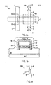
- FIG. la Another such EEPROM device is described by Kupec et al in an article entitled “Triple Level Poly Silicon E 2 PROM with Single Transistor Per Bit", published in the Technical Digest of the International Electronic Devices Meeting, 1980, Washington, D.C., pages 602-606.
- the Kupec et al. cell structure is shown in Figures la-ld.
- cell 100 is formed in a P-type substrate 1 and includes N type diffused regions 2 and 3 which form the source-drain regions of the floating gate transistor 99 of cell 100.
- Contact regions 9 and 8 allow electrical connection from low resistivity interconnect lines (not shown) to source-drain regions 2 and 3, respectively.
- Floating gate 5 is separated from substrate 1 by dielectric 10 and overlies the P type channel region 16 formed between N type source-drain regions 2 and 3. Formed above floating gate 5 is conductive word line 7 which also serves as the control gate of the transistor 99. Word line 7 is separated from floating gate 5 by dielectric 6. Erase line 11 is formed above and surrounding both floating gate 5 and word line 7. Each of the conductive layers 5, 7 and 11 are separated from the others and the substrate by insulation layers 10, 6 and 12. As will be more fully described later, floating gate 5 stores a charge, thereby establishing the control gate threshold voltage of transistor 99 and storing the desired data within memory cell 100.
- Figure lb is a cross-sectional view taken along line BB shown in Figure la.
- a layer of field oxide 10 is formed on P type silicon substrate 1.
- Floating gate is formed on field oxide 10 and covered by insulating layer 6 (typically oxide).
- Word line 7 is formed above and apart from floating gate 5.
- Floating gate 5, oxide 6, and word line 7 are surrounded by dielectric layer 12 (again typically oxide).
- Erase line 11 is formed above and around oxide 12 as shown.
- Figure lc shows a cross-sectional view of the structure of Figure la taken along line CC.
- field oxide 10 is formed on a P-type substrate 1 thereby defining the active area of the device having N-type source-drain regions 2 and 3.
- Gate oxide 4 is formed above the channel region located between source-drain regions 2 and 3.
- Floating gate 5 is formed above gate oxide 4 and covered by oxide 6, upon which word line 7 is formed.
- Word line 7 serves as the gate of transistor 99.
- Oxide 12, which serves as electrical insulation, is formed above and surrounding gate oxide 4, floating gate 5, oxide 6, and word line 7.
- Contact openings 8 and 9 are formed in order to allow electrical connection between low resistivity electrical leads (not shown) and source-drain regions 3 and 2, respectively.
- FIG ld shows the symbolic representation of the floating gate memory cell 100 of Figure la.
- floating gate memory cell 100 includes source-drain regions 2 and 3, floating gate 5, control gate 7 and erase line 11.
- Programming of cell 100 is accomplished by establishing a charge on floating gate 5, which determines the threshold voltage of transistor 99.
- a logical 1 is defined as a low impedence between source-drain regions 2 and 3 when a voltage of approximately 5 volts is applied to control gate 7.
- a logical 0 is defined as a high impedance between source-drain regions 2 and 3 when a voltage of approximately 5 volts is applied to control gate 7. Accordingly, to program a logical 0 state in cell 100, electrons are stored on floating gate 5 by conventional channel injection of hot electrons.
- Erasing memory cell 100 is accomplished by removing the electrons within floating gate 5, thereby returning floating gate 5 to ground potential. This erasure is accomplished, for example, by grounding source-drain region 3 and control gate 7. A high voltage (typically 10 to 20 volts) is placed on the erase line 11, thus causing electrons stored within floating gate 5 to tunnel through regions 15 of oxide 12 to erase line 11.
- a high voltage typically 10 to 20 volts
- FIG. 2 shows a typical array 300 of NxM memory cells 1-1 through N-M, where N is the number of words in the array and M is the number of bits per word. Accordingly, memory array 300 is shown having cell 1-1, providing the first bit of word 1, memory cell 1-M, providing the Mth bit of word 1, cell N-1, providing the first bit of the Nth word, and cell N-M, providing the Mth bit of the Nth word.
- Each of the cells 1-1 through N-M of memory array 300 comprise, for example, EEPROM cells identical to cell 100 shown in Figure la.
- Memory array 300 includes X decoder 304, X driver 308, Y decoder 305, and sense amplifier 306.
- X decoder 304 serves to receive a binary input word defining which word line 303-1 through 303-N is to be selected.
- X driver 308 serves to provide the appropriate voltages on the selected word lines 303-1 through 303-N, and on the remaining deselected word lines.
- Sense amplifier 306 serves, during the read operation, to determine the state of the cell being read.
- memory array 300 may include a plurality of sense amplifiers 306 thus allowing a plurality of cells along a selected word line to be read or written simultaneously, although such additional sense amplifiers are not shown in the figures for the sake of brevity.
- a high voltage is placed on the selected word line 303-1. This places a high voltage (typically 10-20 volts) on each control gate 7 of each cell 1-1 through 1-M.
- Those cells 1-1 through 1-M that are to be programmed to store a logical 0 have a high voltage placed on their associate bit lines 302-1 through 302-M by Y decoder 305 and those cells 1-1 through 1-M which are to be programmed to store a logical 1 have their bit lines placed at ground.
- the Y decoder 305 receives a signal from external circuitry (not shown) which determines which cells are to be programmed to store a logical 0 and which cells are to be programmed to store a logical 1 and selectively applies the proper potential to the bit lines 302-1 through 302-M for proper programming.
- the X decoder 304 receives a similar signal, determines which word line is to have its cells programmed and, through the X driver 308, applies the appropriate voltage to the selected word line and to the remaining deselected word lines to the proper word line 303.
- a potential is applied to word line 303-1.
- This potential is typically 2-5 volts which is sufficient to cause each cell storing a logical 1 (and which have a lower control gate threshold voltage) to turn on, but is insufficient to cause each cell storing a logical 0 (and which have a higher control gate threshold voltage to turn off).
- a potential is applied to each of the bit lines 302-1 to 302-M. Those cells 1-1 through I-M which have been programmed to store a logical 1 will then be conductive, while those that are programmed to store a logical 0 will not.
- the sense amplifier 306 determines which cells are conductive (and therefore have grounded bit lines) and which-are not and supplies this data to external circuitry (not shown).
- the other word lines 303-2 to 303-N are kept at ground potential, and therefore the cells along those word lines do not become conductive, regardless of the data stored in each cell and their control gate threshold voltage.
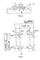
- FIG. 3 shows an array of NxM memory cells, wherein N is the number of words in the array, and M is the number of bits per word.
- the erase lines 11-1 through 11-M are connected in common with each of the bit lines 13-1 through 13-M which are in turn connected through resistor 14 to terminal 19 which is connected to the erase voltage VE.
- the erase voltage VE (typically 10 to 20 volts) is applied through resistor 14 to erase lines 11 and bit lines 13.
- Each word line 7-1 through 7-N is held low.(typically ground).
- the drain of each memory cell 1-1 through N-M is connected to bit line 13 and the source of each memory cell 1-1 through N-M is connected to ground.
- the high voltage applied to erase lines 11-1 through 11-M causes electrons to tunnel from the floating gates of the cells 1-1 through N-M to erase lines 11-1 through 11-M respectively, thus tending to discharge the floating gates of each memory cell 1-1 through N-M of array 101.
- a single one of memory cells 1-1 through N-M is sufficiently erased such that that cell begins to conduct (i.e.
- bit lines 13-1 through 13-M are reduced in potential. Because bit lines 13-1 through 13-M and erase lines 11-1 through 11-M are connected in common during erase, erase lines 11-1 through 11-M are also reduced in potential when a single cell 1-1 through N-M is sufficiently erased to turn on. At this time, erasure of all memory cells 1-1 through N-M of memory array 101 ceases, regardless of whether each memory cell 1-1 through N-M is in fact sufficiently erased.
- this erasure technique prevents the over erasure of cells 1-1 through N-M
- this erasure technique results in the nonsymetrical erasure of memory cells 1-1 through N-M, with the resultant aforesaid problem of undesirable data remaining stored within certain memory cells of memory array 101.
- the voltage required for erasure typically increases, often by more than a factor of 2, after repeated (approximately 10,000) write and erase cycles. Since in most operating conditions some cells of the memory array will never (or seldom) be written into, these cells will not experience any degradation in erase conditions due to tunneling currents during erasure, and therefore, these cells will, over a long period of time, retain their ability to be.erased at a relatively low erase voltage. Thus, these cells will terminate the erase operation before the more heavily exercised cells, which have been repeatedly written and erased and thus have degraded erase characteristics requiring higher erase voltages, are fully erased.
- a bit erasable EEPROM is constructed which alleviates the problems of early termination of erasure and over-erasure. Rather than erasing the entire array at once, and thereby causing the problem of early termination of erasure and over-erasure mentioned above, according to one embodiment of the present invention each cell is erased individually. In another embodiment of this invention, a group of one or more cells on a word line are erased at once with no danger of under or over-erasure of each particular cell. Self-termination of the erase operation of each cell occurs when that cell's.transistor becomes conductive, and at that time the erasure of only that cell ceases. The erasure of a particular cell ceases without effecting the erasure of operation of other cells. Therefore, the electrical erasure is self-limiting for each individual cell.
- a group of one or more cells on a bit line are erased at once with no danger of under or over-erasure of each particular cell.
- Prior art EEPROM devices terminate erasure when current begins to flow in the erase or bit line of the memory array due to the erasure of a single cell, possibly resulting in incomplete erasure of the remaining cells of the array.
- the present invention alleviates this problem of insufficient or over-erasure by allowing each cell along an individual bit line to be independently erased. However, each cell along a particular word line is erased along with the other cells along that particular word line without the danger of over or insufficient erasure.
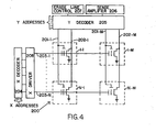
- FIG. 4 shows one embodiment of an EEPROM constructed in accordance with the principles of this invention.
- Memory array 200 of size NxM, includes erase lines 201, bit lines 202-1 through-202-M word lines 203-1 through 203-N, X decoder 204, Y-decoder 205, sense amplifier 206, erase line control 207, X driver 208 and cells 1-1 through N-M.
- N is the number of words in the array and M is the number of bits per word.
- each individual cell is selectively erased without effecting the programmed state of any other cell. This is a significant improvement over prior art EEPROM arrays which required the simultaneous erasure of all cells along an entire word line.
- the erase voltage pulse VE (typically 10-20 volts) is applied for a short period of time (i.e., typically 1 millisecond) through the Y decoder to the selected erase line 201-1 and to the selected bit line 202-1.
- the word line 203-1 corresponding to the cell 1-1 to be erased is held at a low voltage, typically ground.
- the remaining word lines 203-2 through 203-N do not contain cells which are to be erased and are held at a high voltage (typically 10-20 volts).
- This high voltage is capacitively coupled to the floating gates of the cells which are not to be erased, thereby reducing the voltage difference between the erase electrode and the floating gate of each cell which is not to be erased to a value below the voltage difference required to cause tunnelling between the floating gate and the erase terminal.
- all cells on deselected word lines 203-2 through 203-N are not erased.
- a portion of the electrons held on the floating gate of cell 1-1 are injected from the floating gate to the erase line 201-1 of cell 1-1 in response to each erase voltage pulse.
- cell 1-1 will, after a sufficient number of erase pulses, have its control gate threshold voltage reduced to a value corresponding to a logical one (i.e., a low impedance will exist between the source-drain regions of cell 1-1 in response to a voltage of approximately 5 volts applied to the control gate (word line 203-1) of cell 1-1).
- the erase state of each cell being erased is tested after each erase voltage pulse by suitable test circuitry preferably contained in the same integrated circuit device (not shown, but described in the aforementioned published European patent application).
- a plurality of cells along a selected word line are erased simultaneously, with each cell being erased being self-limited only by itself.
- a first cell being erased along a selected word line is sufficiently erased (as determined after one or more erase pulses by suitable test circuitry, not shown)
- its associated erase line is prevented from receiving additional erase pulses, thereby preventing over-erasure of that cell, while allowing the remaining cells along the selected word lines which are to be erased to receive additional erase pulses.
- the circuit shown in the schematic diagram of Figure 4 is suitable for this purpose, merely by adapting Y decoder 205 to provide the erase voltage pulse VE to a selected plurality of erase lines 201-1 through 201-M simultaneously.
- a plurality of cells along a selected bit line are erased simultaneously, with each cell being erased being self-limited only by itself, thus, when a first cell being erased along a selected bit line is sufficiently erased (as determined after one or more erase pulses by suitable test circuitry, not shown), its associated word line is deselected, thereby preventing the erased cell from being further erased upon application of additional erase pulses to its erase line, thereby preventing over-erasure of that cell, while allowing the remaining cells on the selected bit line to be further erased upon receipt of additional erase pulses.
- the present invention alleviates the problem of insufficient erasure by allowing each,cell along either an individual bit line 202-1 through 202-M or along an individual word line 203-1 through 203-N to be independently erased.
- each cell along a particular bit line 202-1 through 202-M (or word line 203-1 through 203-N can be erased along with other selected cells along that particular bit line (or word line), because complete erasure of one of the cells does not result in a drop in the voltage along the other bit lines of the cells being erased.
Landscapes
- Engineering & Computer Science (AREA)
- Microelectronics & Electronic Packaging (AREA)
- Non-Volatile Memory (AREA)
- Read Only Memory (AREA)
Applications Claiming Priority (2)
| Application Number | Priority Date | Filing Date | Title |
|---|---|---|---|
| US43926082A | 1982-11-04 | 1982-11-04 | |
| US439260 | 1982-11-04 |
Publications (2)
| Publication Number | Publication Date |
|---|---|
| EP0108681A2 true EP0108681A2 (de) | 1984-05-16 |
| EP0108681A3 EP0108681A3 (de) | 1986-10-15 |
Family
ID=23743984
Family Applications (1)
| Application Number | Title | Priority Date | Filing Date |
|---|---|---|---|
| EP83402096A Withdrawn EP0108681A3 (de) | 1982-11-04 | 1983-10-27 | Bit-löschbarer EEPROM |
Country Status (2)
| Country | Link |
|---|---|
| EP (1) | EP0108681A3 (de) |
| JP (1) | JPS59116994A (de) |
Cited By (16)
| Publication number | Priority date | Publication date | Assignee | Title |
|---|---|---|---|---|
| EP0317324A3 (de) * | 1987-11-17 | 1991-01-16 | Kabushiki Kaisha Toshiba | Programmierbarer Halbleiterspeicher |
| EP0320916A3 (de) * | 1987-12-15 | 1991-03-27 | Sony Corporation | Elektrisch löschbarer und programmierbarer Festwertspeicher mit Stapelgatterzellen |
| EP0328918A3 (de) * | 1988-01-28 | 1992-03-04 | Kabushiki Kaisha Toshiba | Elektrisch löschbare nichtflüchtige Halbleiterspeichervorrichtung |
| FR2682503A1 (fr) * | 1991-10-09 | 1993-04-16 | Intel Corp | Procede de reparation de cellules sur-effacees contenues dans une memoire flash. |
| US5253200A (en) * | 1987-12-15 | 1993-10-12 | Sony Corporation | Electrically erasable and programmable read only memory using stacked-gate cell |
| EP0541221A3 (de) * | 1991-11-06 | 1994-01-12 | Altera Corp | |
| EP0541222A3 (de) * | 1991-11-06 | 1994-01-19 | Altera Corp | |
| EP0501289A3 (de) * | 1991-02-20 | 1994-02-16 | Sundisk Corp | |
| US5623442A (en) * | 1993-07-13 | 1997-04-22 | Nkk Corporation | Memory cells and memory devices with a storage capacitor of parasitic capacitance and information storing method using the same |
| US5623444A (en) * | 1994-08-25 | 1997-04-22 | Nippon Kokan Kk | Electrically-erasable ROM with pulse-driven memory cell transistors |
| US5729494A (en) * | 1993-05-11 | 1998-03-17 | Nkk Corporation | Non-volatile memory with floating gate type cell transistors and method for adjusting threshold valves of these transistors |
| US5812458A (en) * | 1995-07-31 | 1998-09-22 | Nkk Corporation | Electrically-erasable and programmable ROM with pulse-driven memory cells |
| US5818753A (en) * | 1995-07-31 | 1998-10-06 | Nkk Corporation | Electrically-erasable and programmable ROM with pulse-driven memory cell |
| US6067253A (en) * | 1995-05-30 | 2000-05-23 | Nkk Corporation | Nonvolatile semiconductor memory device capable of suppressing a variation of the bit line potential |
| EP0614568B1 (de) * | 1991-11-26 | 2001-09-19 | Information Storage Devices, Inc. | Programmierbare nichtfluechtige analogs spannungsquelle: einrichtungen und verfahren |
| US7460399B1 (en) | 1989-04-13 | 2008-12-02 | Sandisk Corporation | Flash EEprom system |
Family Cites Families (3)
| Publication number | Priority date | Publication date | Assignee | Title |
|---|---|---|---|---|
| IT1224062B (it) * | 1979-09-28 | 1990-09-26 | Ates Componenti Elettron | Metodo di programmazione per una memoria a semiconduttore non volatile elettricamente alterabile |
| IT1209430B (it) * | 1979-10-08 | 1989-07-16 | Ora Sgs Microelettronica Spa S | Metodo di programmazione per una memoria a semiconduttore nonvolatile elettricamente alterabile del tipo cancellabile per gruppi di celle. |
| US4437174A (en) * | 1981-01-19 | 1984-03-13 | Tokyo Shibaura Denki Kabushiki Kaisha | Semiconductor memory device |
-
1983
- 1983-10-27 EP EP83402096A patent/EP0108681A3/de not_active Withdrawn
- 1983-11-04 JP JP58206118A patent/JPS59116994A/ja active Pending
Cited By (18)
| Publication number | Priority date | Publication date | Assignee | Title |
|---|---|---|---|---|
| EP0317323A3 (de) * | 1987-11-17 | 1991-01-16 | Kabushiki Kaisha Toshiba | Programmierbarer Halbleiterspeicher |
| EP0317324A3 (de) * | 1987-11-17 | 1991-01-16 | Kabushiki Kaisha Toshiba | Programmierbarer Halbleiterspeicher |
| EP0320916A3 (de) * | 1987-12-15 | 1991-03-27 | Sony Corporation | Elektrisch löschbarer und programmierbarer Festwertspeicher mit Stapelgatterzellen |
| US5136541A (en) * | 1987-12-15 | 1992-08-04 | Sony Corporation | Programmable read only memory using stacked-gate cell erasable by hole injection |
| US5253200A (en) * | 1987-12-15 | 1993-10-12 | Sony Corporation | Electrically erasable and programmable read only memory using stacked-gate cell |
| EP0328918A3 (de) * | 1988-01-28 | 1992-03-04 | Kabushiki Kaisha Toshiba | Elektrisch löschbare nichtflüchtige Halbleiterspeichervorrichtung |
| US7460399B1 (en) | 1989-04-13 | 2008-12-02 | Sandisk Corporation | Flash EEprom system |
| EP0501289A3 (de) * | 1991-02-20 | 1994-02-16 | Sundisk Corp | |
| FR2682503A1 (fr) * | 1991-10-09 | 1993-04-16 | Intel Corp | Procede de reparation de cellules sur-effacees contenues dans une memoire flash. |
| EP0541222A3 (de) * | 1991-11-06 | 1994-01-19 | Altera Corp | |
| EP0541221A3 (de) * | 1991-11-06 | 1994-01-12 | Altera Corp | |
| EP0614568B1 (de) * | 1991-11-26 | 2001-09-19 | Information Storage Devices, Inc. | Programmierbare nichtfluechtige analogs spannungsquelle: einrichtungen und verfahren |
| US5729494A (en) * | 1993-05-11 | 1998-03-17 | Nkk Corporation | Non-volatile memory with floating gate type cell transistors and method for adjusting threshold valves of these transistors |
| US5623442A (en) * | 1993-07-13 | 1997-04-22 | Nkk Corporation | Memory cells and memory devices with a storage capacitor of parasitic capacitance and information storing method using the same |
| US5623444A (en) * | 1994-08-25 | 1997-04-22 | Nippon Kokan Kk | Electrically-erasable ROM with pulse-driven memory cell transistors |
| US6067253A (en) * | 1995-05-30 | 2000-05-23 | Nkk Corporation | Nonvolatile semiconductor memory device capable of suppressing a variation of the bit line potential |
| US5812458A (en) * | 1995-07-31 | 1998-09-22 | Nkk Corporation | Electrically-erasable and programmable ROM with pulse-driven memory cells |
| US5818753A (en) * | 1995-07-31 | 1998-10-06 | Nkk Corporation | Electrically-erasable and programmable ROM with pulse-driven memory cell |
Also Published As
| Publication number | Publication date |
|---|---|
| EP0108681A3 (de) | 1986-10-15 |
| JPS59116994A (ja) | 1984-07-06 |
Similar Documents
| Publication | Publication Date | Title |
|---|---|---|
| EP0247875B1 (de) | Blockmässig elektrisch löschbarer Speicher | |
| US5357463A (en) | Method for reverse programming of a flash EEPROM | |
| EP0080560B1 (de) | Speicherzelle mit schwebendem Gatter | |
| EP1203378B1 (de) | Schaltungsausführung zur reduzierung des bitleitungslekcstroms bei programmierungs-und überlöschungskorrekturmodus in einem flash-eeprom | |
| EP0755559B1 (de) | Speichermatrix mit mehrzustandsspeicherzellen | |
| US5491657A (en) | Method for bulk (or byte) charging and discharging an array of flash EEPROM memory cells | |
| US6522584B1 (en) | Programming methods for multi-level flash EEPROMs | |
| US6031766A (en) | Method and circuit for substrate current induced hot e-injection (SCIHE) approach for VT convergence at low Vcc voltage | |
| US6570787B1 (en) | Programming with floating source for low power, low leakage and high density flash memory devices | |
| EP0108681A2 (de) | Bit-löschbarer EEPROM | |
| US5357476A (en) | Apparatus and method for erasing a flash EEPROM | |
| US5329487A (en) | Two transistor flash EPROM cell | |
| US5323351A (en) | Method and apparatus for programming electrical erasable programmable read-only memory arrays | |
| EP0042964B1 (de) | Speichermatrix mit Ein-Transistor-MOS-Zellen mit schwebendem Gate | |
| US5452248A (en) | Method of operating a nonvolatile semiconductor memory device | |
| JPH0845292A (ja) | メモリセル、フラッシュeeprom、メモリセルを消去する方法、およびフラッシュeepromメモリセルを制御する方法 | |
| GB2073488A (en) | Electrically erasable programmable read only memory | |
| EP0661718B1 (de) | Verfahren und Schaltung zum Löschen von Flash-EEPROMs | |
| US6172915B1 (en) | Unified erase method in flash EEPROM | |
| US6363014B1 (en) | Low column leakage NOR flash array-single cell implementation | |
| US5220528A (en) | Compensation circuit for leakage in flash EPROM | |
| US6285588B1 (en) | Erase scheme to tighten the threshold voltage distribution of EEPROM flash memory cells | |
| US20020051387A1 (en) | Method of operating split gate-typed non-volatile memory cell and semiconductor memory device having the cells | |
| US5581502A (en) | Method for reading a non-volatile memory array | |
| EP1623431B1 (de) | Nichtflüchtiger speicher mit einer vorspannung auf der source-elektrode für hci-programmierung |
Legal Events
| Date | Code | Title | Description |
|---|---|---|---|
| PUAI | Public reference made under article 153(3) epc to a published international application that has entered the european phase |
Free format text: ORIGINAL CODE: 0009012 |
|
| AK | Designated contracting states |
Designated state(s): DE FR GB IT NL |
|
| PUAL | Search report despatched |
Free format text: ORIGINAL CODE: 0009013 |
|
| STAA | Information on the status of an ep patent application or granted ep patent |
Free format text: STATUS: THE APPLICATION IS DEEMED TO BE WITHDRAWN |
|
| AK | Designated contracting states |
Kind code of ref document: A3 Designated state(s): DE FR GB IT NL |
|
| 18D | Application deemed to be withdrawn |
Effective date: 19860502 |
|
| RIN1 | Information on inventor provided before grant (corrected) |
Inventor name: TICKLE, ANDREW C. |