EP0108703B1 - Garde-main pour fusil du type à pompe - Google Patents
Garde-main pour fusil du type à pompe Download PDFInfo
- Publication number
- EP0108703B1 EP0108703B1 EP83630176A EP83630176A EP0108703B1 EP 0108703 B1 EP0108703 B1 EP 0108703B1 EP 83630176 A EP83630176 A EP 83630176A EP 83630176 A EP83630176 A EP 83630176A EP 0108703 B1 EP0108703 B1 EP 0108703B1
- Authority
- EP
- European Patent Office
- Prior art keywords
- tube
- forend
- handle
- ring
- assembly according
- Prior art date
- Legal status (The legal status is an assumption and is not a legal conclusion. Google has not performed a legal analysis and makes no representation as to the accuracy of the status listed.)
- Expired
Links
- 239000013536 elastomeric material Substances 0.000 claims description 17
- 230000033001 locomotion Effects 0.000 claims description 12
- 230000003014 reinforcing effect Effects 0.000 claims description 10
- 238000010304 firing Methods 0.000 description 9
- 239000000463 material Substances 0.000 description 2
- 239000002184 metal Substances 0.000 description 2
- 238000005086 pumping Methods 0.000 description 2
- 230000000717 retained effect Effects 0.000 description 2
- 230000005540 biological transmission Effects 0.000 description 1
- 238000010276 construction Methods 0.000 description 1
- 230000002708 enhancing effect Effects 0.000 description 1
Images

Classifications
-
- F—MECHANICAL ENGINEERING; LIGHTING; HEATING; WEAPONS; BLASTING
- F41—WEAPONS
- F41C—SMALLARMS, e.g. PISTOLS, RIFLES; ACCESSORIES THEREFOR
- F41C23/00—Butts; Butt plates; Stocks
- F41C23/16—Forestocks; Handgrips; Hand guards
-
- F—MECHANICAL ENGINEERING; LIGHTING; HEATING; WEAPONS; BLASTING
- F41—WEAPONS
- F41A—FUNCTIONAL FEATURES OR DETAILS COMMON TO BOTH SMALLARMS AND ORDNANCE, e.g. CANNONS; MOUNTINGS FOR SMALLARMS OR ORDNANCE
- F41A35/00—Accessories or details not otherwise provided for
- F41A35/06—Adaptation of guns to both right and left hand use
-
- F—MECHANICAL ENGINEERING; LIGHTING; HEATING; WEAPONS; BLASTING
- F41—WEAPONS
- F41C—SMALLARMS, e.g. PISTOLS, RIFLES; ACCESSORIES THEREFOR
- F41C7/00—Shoulder-fired smallarms, e.g. rifles, carbines, shotguns
- F41C7/02—Pump-action guns, i.e. guns having a reciprocating handgrip beneath the barrel for loading or cocking
Definitions
- This invention relates to a forend assembly for use with a pump gun having a barrel and having a magazine tube at the underside of said barrel extending essentially parallel to the barrel and centered about a predetermined axis, said assembly comprising a forend mounting tube adapted to be received about said magazine tube for manual reciprocation relative thereto along said axis and having an essentially cylindrical external surface, external threads forwardly of said surface, and an essentially forwardly facing shoulder at the rear of said essentially cylindrical surface projecting outwardly beyond the diameter of said surface, a retaining ring received about said forend mounting tube and which has internal threads engaging said external threads thereof and which projects radially outwardly beyond the diameter of said surface, and a forend unit adapted to be received about said mounting tube and having an internal surface disposed about and engaging said external essentially cylindrical surface of said mounting tube.
- the conventional forend element is a unitary rigid structure mounted at the underside of the gun barrel and is free to be manually reciprocated in a front to rear direction relative to the barrel to cock the gun and feed successive rounds of ammunition to the firing chamber.
- the forend may be disposed about an elongated structure extending parallel to the barrel, with that structure usually functioning as a magazine tube for containing a series of shotgun shells or other rounds to be delivered rearwardly to the firing mechanism.
- the object of the present invention is to provide an improved forend assembly for a gun, serving to facilitate holding, cocking and other manipulation of the gun in use.
- the forend assembly is characterized by said forend unit including an outer body of elastomeric material having an outer resiliently deformable surface to be gripped by a user's hand, and a reinforcing tube contained within and more rigid than said elastomeric body and disposed about said essentially cylindrical external surface of said mounting tube axially between said shoulder and said ring at a location to be clamped axially therebetween by threaded tightening of the ring.
- a handle projecting generally transversely of the forend may be connected to the forend for pumping reciprocation therewith to enable the forend and gun to be held and manipulated by this handle in a manner enhancing the overall control characteristics of the gun.
- the transversely projecting handle may be connected to the forend for movement between positions in which the handle projects in different directions from the forend, to enable the handle to be gripped at either the right side or left side of the forend or at its underside.
- Detenting means may be provided for yieldingly retaining the handle in any of its different positions while permitting actuation of the handle from one of those positions to another when desired.
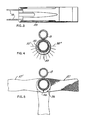
- a pump shotgun which may in most respects be of conventional construction, including the usual receiver 11 carrying firing mechanism actuable by a trigger 12 to fire a shotgun shell received in the rear portion of barrel 13, which is connected at its rear end to the receiver and projects forwardly therefrom along an axis 14.
- a magazine tube 15 extends along an axis 16 parallel to and directly beneath axis 14, and is adapted to contain a series of shotgun shells which are successively fed rearwardly from the tube 15 into the receiver for delivery to the barrel.
- a forend element 17 is disposed about tube 15 and is manually reciprocable along axis 16 relative to the tube between the full line forward position of Fig. 1 and the rear position represented in broken lines at 17'.
- Forend 17 is connected to two conventional parallel action bars 18 which extend rearwardly along the underside of the barrel parallel thereto into receiver 11 and function to actuate the firing mechanism 19 in a relation cocking it as a result of rearward movement of forend 17.
- the rearward and then forward reciprocation of the forend also functions to eject a spent shell from the receiver and gun through a side opening 20, and to feed the next successive shell to the barrel, followed by automatic closure of the rear end of the barrel in preparation for firing of that shell by actuation of trigger 12.
- the gun may have either a conventional rearwardly projecting stock or a pistol type handle represented at 21.
- that assembly may include a tube 22 which is internally and externally cylindrical and is a close fit on the outer cylindrical surface 23 of magazine tube 15 to guide tube 22 for the desired forward and rearward reciprocation along axis 16 about tube 15.
- tube 22 may be suitably connected to the action bars 18, as by providing a ring 24 brazed or otherwise rigidly secured to the outer surface of the tube at its rear end and formed integrally with or rigidly connected to the forward ends of bars 18 to actuate those bars in accordance with front to rear reciprocation of tube 22.
- Forend 17 may include a second internally and externally cylindrical rigid tube 25 which is a close fit on the outer surface of tube 22 and has a transverse annular rear end surface 26 engagable rearwardly against a forwardly facing transverse approximately annular front surface 27 on ring 24 to limit rearward movement of tube 25 on tube 22.
- a retaining ring 28 may be received about the forward end of tube 22 and threadedly connected thereto at 29 to clamp tube 25 rearwardly against shoulder 27 in a manner locking tube 25 in fixed position relative to tube 22.
- tube 25 may rigidly carry an approximately annular detenting ring 30 typically brazed to tube 25 at 31, and having a series of circularly spaced spherically curved concave detenting recesses 32 as represented in Fig. 4. These notches may be distributed along the entire lower half of ring 30, through 180 degrees from the location 32' in Fig. 4 to the location 32". To accommodate these recesses or notches, the lower half of ring 30 may have a greater radial dimension than the upper portion thereof, as shown.
- the forend part 17 may include a body 33 of elastomeric material, preferably rubber typically having a Shore hardness between about 40 and 70 on the A scale.
- This body 33 is bonded internally to tube 25 to remain in fixed position relative thereto and extends substantially entirely thereabout to form an outer sheath or tube having an external surface 34 which is resiliently deformable when contacted by a user's hand to cushion such contact.
- the outer surface 34 of the elastomeric material may be checkered or otherwise irregularized to enhance the frictional contact between a user's hand and that surface and thus further facilitate control, movement and positioning of the forend part by the user.
- Surface 34 except as thus irregularized may be essentially cylindrical about an axis 35 disposed parallel to and slightly beneath axis 16, with all of the axes 14, 16 and 35 preferably lying in a common vertical plane.
- the outer surface of ring 30 may also be centered about the mentioned axis 35.
- ring 30 forwardly, of ring 30, there is disposed about tube 25 another ring 36 which rigidly carries a handle 37 projecting generally transversely or laterally with respect to axis 16.
- handle 37 extends along an axis 38 which intersects axis 16 and may be directly perpendicular thereto.
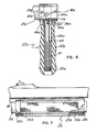
- the handle may include a rigid reinforcing tube 39 centered about axis 38 and carrying a body of elastomeric material 40 completely enclosing tube 39 and having an outer surface 41 engageable by a user's hand.
- the elastomeric material 40 may typically be of the same type of rubber utilized in forming the cushioning portion 33 of forend 17, and may project downwardly beneath the lower end of tube 39 at 42.
- a screw 43 may extend upwardly through the interior of the handle and be threadedly connected to ring 36 at 44 to secure the handle rigidly thereto, with the lower enlarged head screw 43 engaging upwardly against an annular washer 45 embedded within and bonded to the elastomeric material 40 of handle 37 and acting upwardly against the lower end of tube 39 to clamp the tube between washer 45 and ring 36 and thus tightly retain the handle in fixed position relative to ring 36.
- the handle and ring 36 may be turned about tube 25 through 180 degrees between the full line position of Fig. 5 and the oppositely directed broken line position pre-presented at 37'.
- ring 36 carries a detent pin 46 mounted within a recess 47 for movement parallel to axes 14,16 and 35 under the influence of a spring 48.
- the rear end of pin 46 is hemispherically rounded, and is receivable selectively within any of the correspondingly hemispherical notches 32 in ring 36 in a relation releasably retaining the handle in any of the positions in which the pin is received in one of the notches.
- the notches are sufficiently shallow, however, to allow the handle to be forcibly moved between any of those different detenting positions, with the pin being cammed out of one notch by turning force exerted against handle 37 and then being spring returned into another of the notches when the handle reaches a desired newly set position.
- the mounting ring 36 of handle 37 is confined sufficiently closely between ring 28 and ring 30 to allow only rotary motion of handle 37 about axis 16 and retain the handle against axial movement.
- the gun may be carried by a conventional sling strap 49, attached at its rear end to pistol handle 21. Desirably, the forward end of this sling is secured by a connector assembly 50 to the front end of magazine tube 15.
- a cap 51 extends across the forward end of tube 15 and is detachably connectable to the tube by internal threads in the cap engaging external threads on the tube at 52.
- a connector part 53 is secured to the center of the cap by a screw 54 extending through openings in connector 53 and the center of the cap and retained by a nut 55, with the head of the screw acting to retain part 53 against the cap while permitting rotation of part 53 relative to the cap about an axis 56.
- a sling swivel part 57 forms a loop through which the sling strap 49 extends in connecting relation, with the part 57 being appropriately attached to connector 53, desirably in a manner allowing swinging movement of part 57 relative to part 53 about an axis 58.
- a person may first load a series of shells into magazine tube 15 by inserting them forwardly into the magazine through the receiver. An initial one of the shells is then fed into the firing chamber and the gun is cocked by grasping forend 17 through contact with its cushioned elastomeric surface 34 and pumping that forend rearwardly from the full line position of Fig. 1 to the broken line position of that figure, followed by returning forward movement of the forend to its full line position. The gun is then ready to be fired. During such cocking and/or during the firing operation, a user may alternatively hold the forend and gun by grasping handle 37.
- This handle may be directed laterally in either direction to enable a user to hold it with either hand, or may be swung to and detented in any of the intermediate positions in which pin 46 is received within the various notches 32 in ring 30.
- the provision of handle 37 thus improves vastly the overall handling and firing characteristics of the gun.
- the variational form of handle 37a there illustrated includes a rigid reinforcing tube 39a of metal or other suitable material surrounded by a body of rubber or other elastomeric material 40a for cushioning contact of a user's hand with the handle.
- a screw 43a is connected threadedly at 44a into a ring 36a which is disposed about tube 25a and adapted to be rotated relative thereto about axis 16a.
- a detenting ring 30a is brazed to tube 25a, with a ring 28a corresponding to ring 28 of the first form of the invention acting to retain tube 25a on tube 22a.
- the ring 36a is confined at one end by engagement with a shoulder 59 on ring 28a, and at its other end by engagement with a transverse annular shoulder 60 on ring 30a, but with sufficient looseness to allow the desired rotation of ring 36a.
- a detenting pin 46a is carried by the elastomeric material 40a, of handle 37a, and projects upwardly into any of several circularly spaced openings 32a formed in ring 30a, to releasably lock the handle in any of a series of different set positions.
- This detenting engagement can be released by downward movement of handle 37a, against .resistance of a spring 61, which is confined between the enlarged head at the lower end of screw 43a and a plurality of tabs 62 formed by inturned material from the side wall of tube 39a. If the handle 37a is pulled downwardly against the resistance of spring 61, the portions 39a and 40a thereof separate from rings 30a and 36a at 62, thus withdrawing pin 46a from one of the openings 32a and permitting the handle to be turned about axis 16a relative to tube 22a to any of a series of different positions in which the handle projects either rightwardly or leftwardly from the gun or in any intermediate downwardly projecting position. The handle is retained in its new position by releasing it to permit pin 46a to move into a corresponding one of the openings 32a.
- the gun constructed in accordance with Fig. 6 can be handled in essentially the same manner as discussed in connection with Figs. 1 to 5, enabling a user to hold the gun by handle 37a received in either hand and in any desired relative setting with respect to the forend.
- Fig. 7 illustrates another form of the invention in which the forend 17b is similar to unit 17 of the first form of the invention but without provision of the laterally projecting handle 37.
- Forend 17b in Fig. 7 is disposed about a magazine tube 15b, and acts by reciprocation in a front to rear direction relative thereto to actuate the ejecting, loading and cocking mechanism of the gun through movement of action bars 18b.
- the forend includes a first inner preferably metal tube 22b disposed about and fitting closely on magazine 15b and having a ring 24b at its rear end connected to action bars 18b.
- An additional tube 25b corresponding to element 25 of Fig. 2 carries a body of elastomeric material 33b similar to body 33 of Fig.
- a forward retaining ring 28b threadedly connected onto the forward end of tube 22b acts when tightened to clamp tube 25b and the carried elastomeric body 33b axially between ring 28b-and ring 24b, to retain the parts in fixed relative position.
- the elastomeric body 33b may be thicker at the underside of the magazine than at its upper side, in correspondence with the eccentric relationship illustrated in. Fig. 4, and the outer resiliently deformable essentially cylindrical surface of elastomeric body 33b may be checkered or otherwise irregularized.
- a user grasps the outer irregularized resiliently deformable surface of elastomeric forend body 33b and reciprocates the forend rapidly rearwardly and then forwardly as discussed in connection with the first form of the invention.
- the deformability of the surface of elastomeric body 33b cushions the contact between the user's hand and the gun, assists in absorbing recoil forces and the like without transmission to the hand, and in conjunction with the checkering of body 33b enhances the friction between the user's hand and forend in a manner increasing the effectiveness with which the user can control and operate the gun.
Landscapes
- Engineering & Computer Science (AREA)
- General Engineering & Computer Science (AREA)
- Toys (AREA)
- Rehabilitation Tools (AREA)
Claims (10)
Applications Claiming Priority (2)
| Application Number | Priority Date | Filing Date | Title |
|---|---|---|---|
| US06/438,531 US4502238A (en) | 1982-11-01 | 1982-11-01 | Pump gun forend |
| US438531 | 1982-11-01 |
Publications (2)
| Publication Number | Publication Date |
|---|---|
| EP0108703A1 EP0108703A1 (fr) | 1984-05-16 |
| EP0108703B1 true EP0108703B1 (fr) | 1986-12-30 |
Family
ID=23740988
Family Applications (1)
| Application Number | Title | Priority Date | Filing Date |
|---|---|---|---|
| EP83630176A Expired EP0108703B1 (fr) | 1982-11-01 | 1983-10-27 | Garde-main pour fusil du type à pompe |
Country Status (4)
| Country | Link |
|---|---|
| US (1) | US4502238A (fr) |
| EP (1) | EP0108703B1 (fr) |
| JP (1) | JPS59100400A (fr) |
| DE (2) | DE108703T1 (fr) |
Families Citing this family (39)
| Publication number | Priority date | Publication date | Assignee | Title |
|---|---|---|---|---|
| US4663876A (en) * | 1985-01-28 | 1987-05-12 | Reaume Robert N | Stock assembly kit and rifle embodying the same |
| US4827652A (en) * | 1987-10-02 | 1989-05-09 | Martin Ernest J T | Cocking-bar, target-framing and range-finding, carrying, hanging and standing device |
| US4837961A (en) * | 1988-05-03 | 1989-06-13 | Keenan James P | Recoil assembly for pump guns |
| US5027542A (en) * | 1990-06-11 | 1991-07-02 | Simonetti Michael P | Handle for a forearm stock of a pump action gun |
| US5068992A (en) * | 1990-08-13 | 1991-12-03 | Velezis George A | Forearm assembly |
| US5048215A (en) * | 1990-08-30 | 1991-09-17 | Calico Light Weapon Systems | Front grip for a firearm |
| US5417002A (en) * | 1994-04-15 | 1995-05-23 | Guerra; Jorge E. | Adjustable firearm handle |
| BE1008488A3 (fr) * | 1994-07-13 | 1996-05-07 | Browning Sa Societe Anonyme | Fusil pourvu d'un garde-main mobile commandant l'armement. |
| US5613316A (en) * | 1995-03-06 | 1997-03-25 | Hightower; Floyd L. | Shotgun magazine sling attaching device |
| US6055760A (en) * | 1998-04-03 | 2000-05-02 | Cuson; James N. | Forend for minimizing recoil from a gun |
| US6397507B1 (en) * | 2000-08-22 | 2002-06-04 | Marshall Research, Llc | Method and apparatus for a hand-gripable biomechanical tool |
| US6622412B1 (en) | 2001-05-11 | 2003-09-23 | Dave Wilkes | Above barrel grip apparatus |
| US6658781B1 (en) * | 2001-07-31 | 2003-12-09 | Steadyhold Products, Llc | Grip for firearms |
| US7954268B2 (en) * | 2005-05-19 | 2011-06-07 | Blackhawk Industries Product Group Unlimited Llc | Torsion spring recoil system for the forend of a firearm |
| US7340857B1 (en) * | 2005-05-19 | 2008-03-11 | Blackhawk Industries Product Group Unlimited Llc | Recoil system for the forend of a firearm |
| US20100275484A1 (en) * | 2005-05-19 | 2010-11-04 | Bentley James K | Rail mounted recoil system for the forend of a firearm |
| US8205371B1 (en) | 2005-05-19 | 2012-06-26 | Alliant Techsystems Inc. | Recoil reducing systems for a stock |
| US7685755B1 (en) * | 2005-05-19 | 2010-03-30 | Blackhawk Industries Product Group Unlimited Llc | Recoil system |
| US8201354B2 (en) * | 2005-08-29 | 2012-06-19 | Alliant Techsystems Inc. | Recoil system for the forend of a firearm |
| US7770318B2 (en) * | 2005-08-29 | 2010-08-10 | Blackhawk Industries Product Group Unlimited Llc | Recoil system for the forend of a firearm |
| US8122635B2 (en) * | 2005-11-19 | 2012-02-28 | Krow Innovation, Llc | Shotgun forearm-stock shot shell carrier |
| US8353123B2 (en) * | 2005-11-19 | 2013-01-15 | Krow Innovation, Llc | Shotgun forearm-stock shot shell carrier with hidden rail |
| WO2007067569A1 (fr) * | 2005-12-05 | 2007-06-14 | R/M Equipment, Inc. | Ensemble de prehension de fut pour reception sur une arme hote non modifiee |
| US7676975B2 (en) * | 2007-08-16 | 2010-03-16 | Breaching Technologies, Inc. | Tactical foregrip assembly |
| US20090193702A1 (en) * | 2008-01-31 | 2009-08-06 | Lin Ting-Sheng | Articulating firearm fore grip |
| DE102008007341A1 (de) * | 2008-02-04 | 2009-08-06 | Heckler & Koch Gmbh | Zusatzgriff für eine Handfeuerwaffe |
| US20110107643A1 (en) * | 2009-11-06 | 2011-05-12 | Magpul Industries Corporation | Ergonomic Firearm Fore Grip |
| US8215047B2 (en) * | 2010-01-27 | 2012-07-10 | Daniel Defense, Inc. | Systems and methods for adapting a vertical fore grip to a user |
| USD665043S1 (en) | 2010-11-05 | 2012-08-07 | Magpul Industries Corporation | Foregrip for a firearm |
| US8429843B2 (en) * | 2011-04-28 | 2013-04-30 | Leapers, Inc. | Foregrip |
| US8782942B1 (en) * | 2013-09-25 | 2014-07-22 | Krow Innovation, Llc | Forend with sight tunnel |
| US9239210B2 (en) | 2014-04-03 | 2016-01-19 | Magpul Industries Corp. | Firearm accessory mounting interface |
| US9239209B2 (en) * | 2014-04-03 | 2016-01-19 | Magpul Industries, Corp. | Firearm accessory mounting interface |
| US9921029B2 (en) | 2014-01-10 | 2018-03-20 | Magpul Industries Corp. | Connector |
| USD745629S1 (en) | 2014-08-29 | 2015-12-15 | Magpul Industries Corporation | Firearm fore grip |
| US10094635B2 (en) * | 2015-02-11 | 2018-10-09 | Ryker Usa, Inc. | Axially offset foregrip for a firearm and related devices, systems, and methods |
| US9829274B2 (en) * | 2015-03-10 | 2017-11-28 | Matthew John Vallo | Forend with removable cord for firearm |
| FR3065520B1 (fr) * | 2017-04-25 | 2021-06-18 | Safran Electronics & Defense | Poignee de maintien d’une arme et arme comprenant une telle poignee |
| US11428501B2 (en) * | 2021-01-08 | 2022-08-30 | Shaun Tanaka | Interchangeable grip for a firearm |
Family Cites Families (8)
| Publication number | Priority date | Publication date | Assignee | Title |
|---|---|---|---|---|
| US2104129A (en) * | 1937-08-25 | 1938-01-04 | Claude W Kress | Handgrip especially adapted for guns |
| US2331372A (en) * | 1941-01-03 | 1943-10-12 | Remington Arms Co Inc | Firearm |
| US2547180A (en) * | 1948-12-20 | 1951-04-03 | Frank S Taylor | Rifle construction |
| FR1067121A (fr) * | 1952-11-25 | 1954-06-11 | Arme à feu | |
| US2771697A (en) * | 1953-08-10 | 1956-11-27 | Harry A Reising | Removable handgrip for guns |
| US2826848A (en) * | 1955-08-26 | 1958-03-18 | Thomas E Davies | Hand hold for guns |
| US3324588A (en) * | 1965-09-27 | 1967-06-13 | William V T Gilbert | Gunstock |
| US4328633A (en) * | 1980-05-19 | 1982-05-11 | Pachmayr Gun Works, Inc. | Gun with cushioned forend |
-
1982
- 1982-11-01 US US06/438,531 patent/US4502238A/en not_active Expired - Fee Related
-
1983
- 1983-10-27 EP EP83630176A patent/EP0108703B1/fr not_active Expired
- 1983-10-27 DE DE198383630176T patent/DE108703T1/de active Pending
- 1983-10-27 DE DE8383630176T patent/DE3368762D1/de not_active Expired
- 1983-11-01 JP JP58205733A patent/JPS59100400A/ja active Pending
Non-Patent Citations (1)
| Title |
|---|
| Handbook: "An American Rifleman Reprint" * |
Also Published As
| Publication number | Publication date |
|---|---|
| JPS59100400A (ja) | 1984-06-09 |
| US4502238A (en) | 1985-03-05 |
| DE3368762D1 (en) | 1987-02-05 |
| DE108703T1 (de) | 1984-12-06 |
| EP0108703A1 (fr) | 1984-05-16 |
Similar Documents
| Publication | Publication Date | Title |
|---|---|---|
| EP0108703B1 (fr) | Garde-main pour fusil du type à pompe | |
| EP2017564B1 (fr) | Arme portable modulaire | |
| US4520585A (en) | Pistol magazine loading guide | |
| US6658781B1 (en) | Grip for firearms | |
| US5519954A (en) | Ambidextrous magazine release mechanism for firearms | |
| US6877265B2 (en) | System and method for increased magazine capacity for a firearm | |
| US6789342B2 (en) | Firearm | |
| US4676137A (en) | Weapon firearm with magazine | |
| CA1233050A (fr) | Pistolet-mitrailleur a pression des gaz vers l'arriere retardee | |
| US3207037A (en) | Pistol barrel mounting structure | |
| US5105569A (en) | Single shot pistol | |
| US10801803B1 (en) | Archery release | |
| US6226915B1 (en) | Forward angled grip for hand-held weapons and the like | |
| US4689912A (en) | Hand-held high-velocity grenade launcher | |
| US4268987A (en) | Hand weapon for survival purposes | |
| US4837961A (en) | Recoil assembly for pump guns | |
| US3701213A (en) | Revolver firing mechanism with single action and double action movement | |
| US4395938A (en) | Gas cylinder plug for a gas operated machine gun | |
| US6622412B1 (en) | Above barrel grip apparatus | |
| US4492145A (en) | Feeding mechanism for a gas operated machine gun | |
| US3656399A (en) | Stock and trigger mechanism for line thrower | |
| US20200309474A1 (en) | Semi-automatic rifle restrictors and methods | |
| US20160061548A1 (en) | System for a Retrofit Trigger Actuating Mechanism Integrated Into a Semi-Automatic Rifle | |
| EP0108031B1 (fr) | Crosse amortisseuse amovible pour fusil | |
| US20180259279A1 (en) | Semi-automatic rifle restrictor mechanism |
Legal Events
| Date | Code | Title | Description |
|---|---|---|---|
| PUAI | Public reference made under article 153(3) epc to a published international application that has entered the european phase |
Free format text: ORIGINAL CODE: 0009012 |
|
| AK | Designated contracting states |
Designated state(s): BE DE GB IT |
|
| ITCL | It: translation for ep claims filed |
Representative=s name: RICCARDI SERGIO & CO. |
|
| 17P | Request for examination filed |
Effective date: 19840914 |
|
| DET | De: translation of patent claims | ||
| GRAA | (expected) grant |
Free format text: ORIGINAL CODE: 0009210 |
|
| AK | Designated contracting states |
Kind code of ref document: B1 Designated state(s): BE DE GB IT |
|
| REF | Corresponds to: |
Ref document number: 3368762 Country of ref document: DE Date of ref document: 19870205 |
|
| ITF | It: translation for a ep patent filed | ||
| PLBE | No opposition filed within time limit |
Free format text: ORIGINAL CODE: 0009261 |
|
| STAA | Information on the status of an ep patent application or granted ep patent |
Free format text: STATUS: NO OPPOSITION FILED WITHIN TIME LIMIT |
|
| 26N | No opposition filed | ||
| ITTA | It: last paid annual fee | ||
| PGFP | Annual fee paid to national office [announced via postgrant information from national office to epo] |
Ref country code: GB Payment date: 19930927 Year of fee payment: 11 Ref country code: DE Payment date: 19930927 Year of fee payment: 11 |
|
| PGFP | Annual fee paid to national office [announced via postgrant information from national office to epo] |
Ref country code: BE Payment date: 19930928 Year of fee payment: 11 |
|
| PG25 | Lapsed in a contracting state [announced via postgrant information from national office to epo] |
Ref country code: GB Effective date: 19941027 |
|
| PG25 | Lapsed in a contracting state [announced via postgrant information from national office to epo] |
Ref country code: BE Effective date: 19941031 |
|
| BERE | Be: lapsed |
Owner name: PACHMAYR GUN WORKS INC. Effective date: 19941031 |
|
| GBPC | Gb: european patent ceased through non-payment of renewal fee |
Effective date: 19941027 |
|
| PG25 | Lapsed in a contracting state [announced via postgrant information from national office to epo] |
Ref country code: DE Effective date: 19950701 |
|
| ZE | Nl: corrections to earlier entries in headings pe - xe |
Free format text: PAT.BUL.19/95 PATENT NO.0108703 SHOULD BE DELETED |