EP0108816A1 - Dispositif d'antennes fonctionnant en diversité sensible aux composantes du champ électromagnétique - Google Patents
Dispositif d'antennes fonctionnant en diversité sensible aux composantes du champ électromagnétique Download PDFInfo
- Publication number
- EP0108816A1 EP0108816A1 EP82109772A EP82109772A EP0108816A1 EP 0108816 A1 EP0108816 A1 EP 0108816A1 EP 82109772 A EP82109772 A EP 82109772A EP 82109772 A EP82109772 A EP 82109772A EP 0108816 A1 EP0108816 A1 EP 0108816A1
- Authority
- EP
- European Patent Office
- Prior art keywords
- antenna
- pair
- antenna elements
- field component
- elements
- Prior art date
- Legal status (The legal status is an assumption and is not a legal conclusion. Google has not performed a legal analysis and makes no representation as to the accuracy of the status listed.)
- Ceased
Links
- 230000005684 electric field Effects 0.000 claims abstract description 12
- 238000005562 fading Methods 0.000 claims abstract description 9
- 230000005404 monopole Effects 0.000 claims abstract description 4
- 238000000926 separation method Methods 0.000 description 4
- 238000000034 method Methods 0.000 description 3
- 238000004891 communication Methods 0.000 description 2
- 238000010295 mobile communication Methods 0.000 description 2
- 238000012935 Averaging Methods 0.000 description 1
- 230000015556 catabolic process Effects 0.000 description 1
- 230000002596 correlated effect Effects 0.000 description 1
- 238000006731 degradation reaction Methods 0.000 description 1
- 238000012986 modification Methods 0.000 description 1
- 230000004048 modification Effects 0.000 description 1
- 230000010287 polarization Effects 0.000 description 1
- 230000001902 propagating effect Effects 0.000 description 1
Images

Classifications
-
- H—ELECTRICITY
- H01—ELECTRIC ELEMENTS
- H01Q—ANTENNAS, i.e. RADIO AERIALS
- H01Q21/00—Antenna arrays or systems
- H01Q21/06—Arrays of individually energised antenna units similarly polarised and spaced apart
-
- H—ELECTRICITY
- H04—ELECTRIC COMMUNICATION TECHNIQUE
- H04B—TRANSMISSION
- H04B7/00—Radio transmission systems, i.e. using radiation field
- H04B7/02—Diversity systems; Multi-antenna system, i.e. transmission or reception using multiple antennas
- H04B7/10—Polarisation diversity; Directional diversity
Definitions
- the present invention relates to antenna arrangements and more particularly to a diversity antenna arrangement to receive a transmitted signal in a multipath fading environment.
- HF high frequency
- VHF very high frequency
- space diversity and angle-arrival diversity need either many spaced antennas or a large size directional antenna which are often not very practical because of the large wavelength in this frequency range.
- Polarization diversity has a 3.0 dB (decibel) power degradation by using two polarized transmitting antennas for diversity purposes.
- An object of the present invention is to provide a simple diversity antenna arrangement for utilization in the HF and VHF frequency range.
- Another object of the present invention is to provide a simple field component diversity antenna arrangement for the HF and VHF frequency range.
- a feature of the present invention is the provision of a field component diversity antenna arrangement to receive uncorrelated electric field and magnetic field components of a transmitted signal in a multipath fading environment comprising: at least a first pair of spaced elemental antenna elements disposed to receive the transmitted signal; and a first hybrid circuit coupled to the first pair of spaced antenna elements to provide a first output signal proportional to the electric field component and a second output signal proportional to the magnetic field component.
- a dipole antenna is used to receive an electric wave and a loop antenna is used to receive a magnetic field.
- an antenna arrangement will be employed which can receive both the electric field and the magnetic field at the same time. Based upon a multipath fading or reflection phenomena at a sky wave,. it has been proved that the electric field component and the magnetic field component are received uncorrelated in a troposcatter communication link or other fading environments.
- the reason for using the field component diversity antenna arrangement is that the separation of elemental antenna elements can be much smaller than that required in usual space diversity.
- the implementation of this type of antenna is simple and the signal performance due to this diversity antenna arrangement is effective especially at the HF and VHF frequency range.
- the theoretical field component diversity antenna arrangement 1 includes two elemental antenna elements 2 and 3 extending from a ground plane 4 spaced from each other a distance a and connected by a connecting member 5 to essentially form a loop.
- the output from each of the antenna elements 2 and 3 is coupled to a hybrid circuit 6 to obtain an electric field component output signal E by summing the two inputs to hybrid circuit 6 and to obtain a magnetic field component output signal H by subtracting one input thereto from the other input thereto.
- the output signals E and H have been proven to be independent signals after passing through a multipath reflection or fading medium; see, for instance, an article by W.C.Y. Lee, Bell System Technical Journal, Vol. 46, page 417, February 1967.
- any kind of diversity combining techniques can be used to realize the advantage of the diversity scheme.
- Various combining techniques that can be employed are disclosed in the book by Schwartz, Bennett and Stein entitled “Communication Systems and Techniques", McGraw-Hill, 1966, pages 416 - 498.
- Fig. 1 The dimensions illustrated in Fig. 1 are for an operating frequency of 10 MHz (megahertz) and the hybrid circuit is an off-the-shelf item that is obtainable from a number of different manufacturers, for instance, Narda and Triplate.
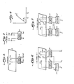
- Figs. 2 and 3 illustrate one practical embodiment of the field component diversity antenna arrangement of the present invention.
- This embodiment is a corner reflector antenna having the two elemental antenna elements 7 and 8 spaced an amount 0.125A (wavelength) at the operating frequency of the antenna in a cooperative association with a corner reflector 9.
- the elemental antenna elements 7 and 8 are dipole elements whose outputs are coupled to the hybrid circuit 10 to produce the E and H output signals.
- Fig. 4 shows a second practical embodiment of the field component diversity antenna arrangement of the present invention including two monopole elemental antenna elements 11 and 12 in a cooperative relationship with a ground plane 13. Monopole antenna elements 11 and 12 are separated by 0.125X and are connected to a hybrid circuit 14 to provide the E and H output signals.
- Fig. 5 shows a third practical embodiment of the field component diversity antenna arrangement of the present invention including elemental dipole antenna elements 15 and 16 whose outputs are coupled to a hybrid circuit 17 to produce the E and H output signals.
- a fourth practical embodiment of the field component diversity antenna arrangement having two pairs of elemental antenna elements with the first pair of antenna elements 18 and 19 being oriented at right angles with respect to the second pair of antenna elements 20 and 21 with each of the elements of each of the pair of elements being spaced 0.125 ⁇ from each other.
- the output from antenna elements 18 and 19 are coupled to a hybrid circuit 22 and the output of antenna elements 20 and 21 are coupled to a hybrid circuit 23.
- Hybrid circuits 22 and 23 produce two components of the H output signal, namely, Hx and Hy components and two electric field component output signals which are combined in summer 24 to provide an E output signal.
- Fig. 7 shows a modification of the embodiment of Fig. 6 wherein a second summer 25 is employed to combine the H signal components Hx and Hy to provide a H signal output from the antenna arrangement.
- the embodiments shown in Figs 2 to 7 are particularly useful in mobile communications. For instance, at 30 MHz the wavelength is 10 meters.
- the separation for space diversity requires one half wavelength, i.e., 5 meters. It becomes impossible to mount two antennas separated 5 meters apart on the roof of a jeep or regular vehicle. For this reason, the field component diversity antenna arrangement has great merit. It only needs a separation of 0.125 ⁇ apart between the two antenna elements. Therefore, the two antenna elements need to be spaced only 1.25 meters apart.
- the embodiments of Figs. 6 and 7 are improvements in the embodiments of Figs. 2 - 5 to improve the efficiency thereof in mobile communication application but the advantage is still there in all of the embodiments, namely, the ability to provide separation between one or two pairs of antenna elements which can be accommodated on a jeep or other regular vehicles.
- Ez 1 and Ez2 expressed as: and where A u is a complex amplitude of an electric wave propa- gating at a direction u, and u is a unit vector related to an angle 0 between u and x as shown in Fig. 8. S is the wave number and N is the number of wave arrivals. Ez 1 and Ez 2 can also be expressed in real and imaginary parts as shown in equations (1) and (2), respectively.
- the two outputs W1 and W 2 of a field component diversity antenna as shown in Fig. 4 can be expressed as:
- Equation (3) and (4) will be examined. If Ez 1 and E z 2 are highly correlated, then the mean value of W 2 , W 2 is much smaller than W 1 . There is no advantage in combining them even when W 1 and W 2 are uncorrelated. In order to keep W 1 and W 2 the same, it may be necessary to let the correlation of Ez 1 and Ez 2 be 0.5, as follows:
- the spacing between the two elemental antenna elements is 0.175 ⁇ , but from the experimental results, the spacing between the elemental antenna elements is 0.125 ⁇ , which is smaller than the theoretical value.
Landscapes
- Engineering & Computer Science (AREA)
- Computer Networks & Wireless Communication (AREA)
- Signal Processing (AREA)
- Variable-Direction Aerials And Aerial Arrays (AREA)
Priority Applications (1)
| Application Number | Priority Date | Filing Date | Title |
|---|---|---|---|
| EP82109772A EP0108816A1 (fr) | 1982-10-22 | 1982-10-22 | Dispositif d'antennes fonctionnant en diversité sensible aux composantes du champ électromagnétique |
Applications Claiming Priority (1)
| Application Number | Priority Date | Filing Date | Title |
|---|---|---|---|
| EP82109772A EP0108816A1 (fr) | 1982-10-22 | 1982-10-22 | Dispositif d'antennes fonctionnant en diversité sensible aux composantes du champ électromagnétique |
Publications (1)
| Publication Number | Publication Date |
|---|---|
| EP0108816A1 true EP0108816A1 (fr) | 1984-05-23 |
Family
ID=8189302
Family Applications (1)
| Application Number | Title | Priority Date | Filing Date |
|---|---|---|---|
| EP82109772A Ceased EP0108816A1 (fr) | 1982-10-22 | 1982-10-22 | Dispositif d'antennes fonctionnant en diversité sensible aux composantes du champ électromagnétique |
Country Status (1)
| Country | Link |
|---|---|
| EP (1) | EP0108816A1 (fr) |
Cited By (6)
| Publication number | Priority date | Publication date | Assignee | Title |
|---|---|---|---|---|
| EP0749216A1 (fr) * | 1995-06-14 | 1996-12-18 | SIP SOCIETA ITALIANA PER l'ESERCIZIO DELLE TELECOMUNICAZIONI P.A. | Antenne fonctionnant en diversité, notamment pour systèmes de communication mobiles et microcellulaires, et procédé de communication utilisant une telle antenne |
| WO1997029558A1 (fr) * | 1996-02-08 | 1997-08-14 | Orange Personal Communications Services Ltd. | Disposition d'antennes |
| WO2004008657A1 (fr) * | 2002-07-11 | 2004-01-22 | Koninklijke Philips Electronics N.V. | Ameliorations apportees aux systemes de communications sans fil a canaux de transmission multiples |
| WO2006120250A3 (fr) * | 2005-05-13 | 2007-04-12 | Fractus Sa | Systeme a diversite d'antenne et composant d'antenne a fente |
| US7292195B2 (en) | 2005-07-26 | 2007-11-06 | Motorola, Inc. | Energy diversity antenna and system |
| WO2007136747A3 (fr) * | 2006-05-18 | 2008-10-16 | Univ California | Antennes couplées étroitement pour supergain et diversité |
Citations (6)
| Publication number | Priority date | Publication date | Assignee | Title |
|---|---|---|---|---|
| US2897496A (en) * | 1955-01-12 | 1959-07-28 | Rca Corp | Corner reflector antenna |
| US3036301A (en) * | 1952-12-05 | 1962-05-22 | Raytheon Co | Communication systems |
| US3172111A (en) * | 1962-08-30 | 1965-03-02 | Louis D Breetz | Multi-polarized single element radiator |
| US3475756A (en) * | 1967-10-19 | 1969-10-28 | Avanti R & D Inc | Polarization diversity loop antenna |
| DE1541724A1 (de) * | 1965-09-29 | 1970-02-19 | Western Electric Co | Funkempfangsgeraet,das sowohl auf elektrische als auch auf magnetische Feldkomponenten des uebertragenen Signals anspricht |
| US4217591A (en) * | 1978-09-20 | 1980-08-12 | The United States Of America As Represented By The Secretary Of The Army | High frequency roll-bar loop antenna |
-
1982
- 1982-10-22 EP EP82109772A patent/EP0108816A1/fr not_active Ceased
Patent Citations (6)
| Publication number | Priority date | Publication date | Assignee | Title |
|---|---|---|---|---|
| US3036301A (en) * | 1952-12-05 | 1962-05-22 | Raytheon Co | Communication systems |
| US2897496A (en) * | 1955-01-12 | 1959-07-28 | Rca Corp | Corner reflector antenna |
| US3172111A (en) * | 1962-08-30 | 1965-03-02 | Louis D Breetz | Multi-polarized single element radiator |
| DE1541724A1 (de) * | 1965-09-29 | 1970-02-19 | Western Electric Co | Funkempfangsgeraet,das sowohl auf elektrische als auch auf magnetische Feldkomponenten des uebertragenen Signals anspricht |
| US3475756A (en) * | 1967-10-19 | 1969-10-28 | Avanti R & D Inc | Polarization diversity loop antenna |
| US4217591A (en) * | 1978-09-20 | 1980-08-12 | The United States Of America As Represented By The Secretary Of The Army | High frequency roll-bar loop antenna |
Cited By (9)
| Publication number | Priority date | Publication date | Assignee | Title |
|---|---|---|---|---|
| EP0749216A1 (fr) * | 1995-06-14 | 1996-12-18 | SIP SOCIETA ITALIANA PER l'ESERCIZIO DELLE TELECOMUNICAZIONI P.A. | Antenne fonctionnant en diversité, notamment pour systèmes de communication mobiles et microcellulaires, et procédé de communication utilisant une telle antenne |
| WO1997029558A1 (fr) * | 1996-02-08 | 1997-08-14 | Orange Personal Communications Services Ltd. | Disposition d'antennes |
| US6469680B1 (en) | 1996-02-08 | 2002-10-22 | Orange Personal Communications Services Limited | Antenna arrangement |
| CN100372264C (zh) * | 1996-02-08 | 2008-02-27 | 奥林吉个人通讯服务公司 | 天线结构 |
| WO2004008657A1 (fr) * | 2002-07-11 | 2004-01-22 | Koninklijke Philips Electronics N.V. | Ameliorations apportees aux systemes de communications sans fil a canaux de transmission multiples |
| WO2006120250A3 (fr) * | 2005-05-13 | 2007-04-12 | Fractus Sa | Systeme a diversite d'antenne et composant d'antenne a fente |
| US8531337B2 (en) | 2005-05-13 | 2013-09-10 | Fractus, S.A. | Antenna diversity system and slot antenna component |
| US7292195B2 (en) | 2005-07-26 | 2007-11-06 | Motorola, Inc. | Energy diversity antenna and system |
| WO2007136747A3 (fr) * | 2006-05-18 | 2008-10-16 | Univ California | Antennes couplées étroitement pour supergain et diversité |
Similar Documents
| Publication | Publication Date | Title |
|---|---|---|
| US8253645B2 (en) | Method and device for coupling cancellation of closely spaced antennas | |
| CA1264373A (fr) | Antenne plate large bande | |
| US4922259A (en) | Microstrip patch antenna with omni-directional radiation pattern | |
| EP0762542A2 (fr) | Diversité d'antennes | |
| Vaughan et al. | Closely spaced monopoles for mobile communications | |
| CA2435099A1 (fr) | Dispositif d'antenne perfectionne pour systemes de communication a entrees multiples et sorties multiples | |
| US6229484B1 (en) | Dual polarized flat antenna device | |
| EP1058340A1 (fr) | Antenne, dispositif radio et repetiteur radio | |
| CA2330037C (fr) | Antenne polarisee circulairement a gauche pour systemes gps | |
| PL180089B1 (pl) | Sposób i urzadzenie do lacznosci przy uzyciu fal elektromagnetycznych PL PL PL PL PL PL PL PL PL PL PL | |
| EP0325034A3 (fr) | Antenne réseau | |
| US5499033A (en) | Polarization diversity antenna | |
| CA2093161A1 (fr) | Raidateur planar a large bande pouvant etre monte en reseau | |
| CA2208467A1 (fr) | Structure rayonnante a deux bandes et a deux polarisations | |
| US4611212A (en) | Field component diversity antenna and receiver arrangement | |
| US6107967A (en) | Billboard antenna | |
| US5304998A (en) | Dual-mode communication antenna | |
| EP0108816A1 (fr) | Dispositif d'antennes fonctionnant en diversité sensible aux composantes du champ électromagnétique | |
| Dinger | Some potential antenna applications of high-temperature superconductors | |
| US3144647A (en) | Diversity system | |
| Karode et al. | Frequency offset retrodirective antenna array | |
| Taga | Characteristics of space‐diversity branch using parallel dipole antennas in mobile radio communications | |
| CA1201200A (fr) | Montage d'antenne a diverses composantes de champ | |
| US3475756A (en) | Polarization diversity loop antenna | |
| Lawrence et al. | A polarimetric line-of-sight channel model for MIMO satellite communications |
Legal Events
| Date | Code | Title | Description |
|---|---|---|---|
| PUAI | Public reference made under article 153(3) epc to a published international application that has entered the european phase |
Free format text: ORIGINAL CODE: 0009012 |
|
| AK | Designated contracting states |
Designated state(s): BE CH DE FR GB LI NL |
|
| 17P | Request for examination filed |
Effective date: 19840717 |
|
| STAA | Information on the status of an ep patent application or granted ep patent |
Free format text: STATUS: THE APPLICATION HAS BEEN REFUSED |
|
| 18R | Application refused |
Effective date: 19880519 |
|
| RIN1 | Information on inventor provided before grant (corrected) |
Inventor name: LEE, WILLIAM CHIEN-YEH |