EP0109058A2 - Aufbau einer Kraftfahrzeugtür - Google Patents
Aufbau einer Kraftfahrzeugtür Download PDFInfo
- Publication number
- EP0109058A2 EP0109058A2 EP83111239A EP83111239A EP0109058A2 EP 0109058 A2 EP0109058 A2 EP 0109058A2 EP 83111239 A EP83111239 A EP 83111239A EP 83111239 A EP83111239 A EP 83111239A EP 0109058 A2 EP0109058 A2 EP 0109058A2
- Authority
- EP
- European Patent Office
- Prior art keywords
- door
- door glass
- glass
- guide
- motor vehicle
- Prior art date
- Legal status (The legal status is an assumption and is not a legal conclusion. Google has not performed a legal analysis and makes no representation as to the accuracy of the status listed.)
- Granted
Links
Images


Classifications
-
- B—PERFORMING OPERATIONS; TRANSPORTING
- B60—VEHICLES IN GENERAL
- B60J—WINDOWS, WINDSCREENS, NON-FIXED ROOFS, DOORS, OR SIMILAR DEVICES FOR VEHICLES; REMOVABLE EXTERNAL PROTECTIVE COVERINGS SPECIALLY ADAPTED FOR VEHICLES
- B60J10/00—Sealing arrangements
- B60J10/70—Sealing arrangements specially adapted for windows or windscreens
- B60J10/74—Sealing arrangements specially adapted for windows or windscreens for sliding window panes, e.g. sash guides
- B60J10/79—Sealing arrangements specially adapted for windows or windscreens for sliding window panes, e.g. sash guides for flush-glass windows, i.e. for windows flush with the vehicle body or the window frame
Definitions
- This invention relates to construction of a door in a motor vehicle, and more particularly to improvements in construction of a door in a motor vehicle, wherein the outer surface of a door glass and the outer surface of a door frame are substantially flush with each other.
- the door glass is expanded out due to a difference in pressure between the interior and the exterior of a compartment during running of the motor vehicle at high speed.
- the outer surface of the guide and the outer surface of the door glass should necessarily have a difference in stage therebetween.
- the sealing between the door glass 1 and the door frame 3 is effected by a door glass weather strip 6 being in contact with a corner portion of the end edge 1A of the door glass 1, and the outer surface 6A of this door glass weather strip 6 and the outer surface 3A of the door frame 3 disposed on the side of the outer periphery of this door glass weather strip 6 are made substantially flush with the outer surface of the door glass 1.
- the present invention has been developed to obviate the above-described disadvantages of the prior art and has as its object the provision of a construction of a door in a motor vehicle, wherein the width and the value of projection into the compartment of the door frame are reduced while the door frame has a sufficient rigidity and the sealing between the door glass and the door frame is secured.
- the present invention has been developed to obviate the above-described disadvantages of the prior art and has as its object the provision of a construction of the door in a motor vehicle, wherein the width and the value of projection into the compartment of the door frame are reduced while the door frame has a sufficient rigidity, the sealing between the door glass and the door frame is secured and the sliding wear between the slide pieces and the guide groove is decreased.
- the present invention has been developed to obviate the above-described disadvantages of the prior art and has as its object the provision of a construction of the door in a motor vehicle, wherein the sealing between the end edge of the door glass and the door frame is easily secured, the end edges of the door glass and the slide : pieces are made invisible to improve the appearance of the vehicle, and the intrusion of dust and the like into the sliding portion between the door glass and the door frame is prevented.
- the present invention contemplates that in the construction of the door in the motor vehicle, wherein the slide pieces secured to the end portions of the door glass are slidable coupled into the guide groove of a guide portion of the door frame to thereby guide the door glass in the vertical direction and the outer surface of the door glass and the outer surface of the door frame are substantially flush with each other, a door glass weather strip for sealing between the door glass and the door frame is provided to the compartment's side from the guide portion.
- the present invention contemplates that in the construction of the door in the motor vehicle, wherein the slide pieces secured to the end portions of the door glass are slidable coupled into the guide groove of a guide portion of the door frame to thereby guide the door glass in the vertical direction and the outer surface of the door glass and the outer surface of the door frame are substantially flush with each other, there are provided a door glass weather strip for sealing between the door glass and the door frame at a position to the compartment's side from the guide portion and a glass run provided in the guide groove in the guide portion, for smoothly, slidably guiding in the inner surface thereof the slide pieces.
- each of the slide pieces is secured to the forward end of a bracket projecting outwardly from an end portion of the door glass in a direction substantially parallel to the surface of the door glass, each of the guide grooves being open toward the end portion of the door glass and surrounding the slide piece is provided and the outer wall surface of the guide portion is substantially flush with the door glass.
- the present invention contemplates that, in the aforesaid construction of the door in the motor vehicle, a portion of the glass run disposed outwardly of the door is extended along the outer surface of the door glass to form a fin portion for sealing the outer surface of the end portion of the door glass, whereby the intrusion of dust and the like into the sliding portion between the door glass and the door frame is prevented, and the end portion of the door glass and the slide piece are made invisible from outside.
- the present invention contemplates that, in the aforesaid construction of the door in the motor vehicle, the forward end of the fin portion of the glass run in its free condition is opposed to the door glass weather strip, whereby the sealing properties are further improved.
- the present invention contemplates that, in the aforesaid construction of the door in the motor vehicle, the forward end of the fin portion of the glass run in its free condition is supported on the forward end of the door glass weather strip, so that the sliding portion between the end portion of the door glass and the door frame can be sealed even in the free condition.
- each of the brackets for supporting the slide piece is chamfered at end portions of the outer surface, which are disposed in the vertical direction, whereby the frictional resistance between the slide pieces and the fin portion is decreased during the vertical movement of the door glass without affecting the sealing properties.
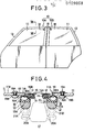
- a door glass weather strip 16 for sealing between the door glass 11 and the door frame 13 is provided at a position to the side of a compartment 17 from the guide portion 14.
- the slide piece 12 is secured to the forward end of a bracket 18 projecting outwardly from the end portion of the door glass in a direction substantially parallel to the glass surface, the guide portion 14 is provided with the guide groove 15 being open toward the end portion of the door glass 11 and surrounding the slide piece 12 and the outer wall surface 14A of the guide portion 14 is substantially flush with the door glass 11.
- the slide pieces 12 are formed of synthetic resin members modled to the forward ends of the brackets 18 which are clamped and fixed to the front side door 10A by screws 19A and nuts 19B at the lower forward end portion, the top end of the rear end edge and the bottom end thereof.
- the bracket 18 is formed into a crank shape and consequently the slide piece 12 is offset from the door glass 11 toward the compartment 17, so that the outer wall surface 14A of the guide portion 14 can be substantially flush with the outer surface of the door glass 11.
- the door glass weather strip 16 is disposed on the side of the compartment 17 with respect to the door glass 11, supported by an outwardly directed channel portion 13A formed on the door frame 13, one 16A of lips thereof is constantly in contact with the inner surface of the end edge llA of the door glass 11, and the other 16B of the lips is adapted to close the guide groove 15 of the guide portion 14 as indicated by two-dot chain lines in Fig. 4 at a portion where the other 16B of the lips does not contact the bracket 18.
- the guide portion 14 is offset in the direction opposite to the door glass 11 with respect to the door glass weather strip 16 and the main body of the door frame 13.
- Fig. 4 designated at 20 is a center pillar, 21A and 21B door weather strips, respectively.
- the center pillar 20 is disposed such that, when the front side door l0A and rear side door 10B are closed, the center pillar is shielded substantially invisibly from outside by the guide portions 14 of the door frames 13 of the both doors. More specifically, the guide portions 14 are offset from the main bodies of the door frames 13 to the extent where the guide portions can shield the center pillar 20. Furthermore, the door weather strips 21A and 21B are secured to a flange portion 20A of the center pillar 20 and adapted to be in contact with the front side door 10A and rear side door 10B at the rear surfaces of the outwardly directed channel portions 13A of the door frames 13 of the both doors when the both doors are closed.
- the guide portion 14 of the door frame 13 is projected into a space formed between a door inner panel 27A and a door outer panel 27B in the same manner as in the conventional construction of the door as shown in Fig. 6.
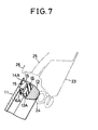
- a portion of the door frame 13 forming the top part and thereabout is adapted to be in contact with a door weather strip 24 secured to a roof side rail 23 as shown in Fig. 7.
- a door weather strip 24 secured to a roof side rail 23 as shown in Fig. 7.
- 25 is a roof and 26 a drip channel, respectively.
- the lip 16B of the door glass weather strip 16 on the side of the guide portion 14 is omitted because the lip may interfere with the slide piece 16 when the door glass 11 is fully closed.
- the door glass weather strip 16 is disposed to the side of the compartment 17 from the guide portion 14 of the door frame 13, whereby the size of the door glass weather strip 16 in the width-wise direction is not restricted by the guide portion 14, so that the scope of contact with the door glass 11 can be increased, thus enabling to secure the sealing without increasing the width of the guide portion 14.
- the guide portion 14 is disposed along the outer periphery of the door glass 11, so that the value of projection of the guide portion into the compartment 17 can be reduced.
- the guide portions 14 are provided along the end edges 11A in front and at the rear of the door glasses 11, so that the guide portions 14 can shield the pillar, thereby enabling to offer an advantage of shielding the pillar without increasing the width of each of the door frames l.
- the three slide pieces 12 are secured to the door glass 11 at the forward and rear ends thereof, however, the present invention need not necessarily be limited to this, and, each of slide pieces or four slide pieces, etc. may be secured to the forward and rear ends of the door glass, and the positions of securing the slide pieces may be such that three or more slide pieces are disposed in the vertical direction along the end edge 11A at the rear portion of the door glass 11 in the front side door l0A for example.
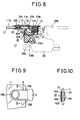
- the slide pieces 12 secured to the end portion 11A of door glass 11 of the front side door 10A are slidably coupled into the guide groove 15 of the guide portion 14 of the guide frame 13 to thereby guide the door glass 11 in the vertical direction and the outer surface of the door glass 11 and the outer surface of the door frame 13 are substantially flush with each other, there are provided the door glass weather strip 16 for sealing between the door glass 11 and the door frame 13 at the position to the side of the compartment 17 from the guide portion 14 and the glass run 27 provided in the guide groove 15 of the guide portion 14 for smoothly, slidably guiding in the inner surface thereof the slide pieces 12.
- the glass run 27 is made of hard and flexible resin or the like, formed into substantially a U-shape in cross section disposed along the inner surface of the guide groove 15 of the guide portion 14 and a portion of the glass run 27 disposed outwardly of the door is extended along the outer surface 11B of the door glass 11 to be formed into a fin portion 27A for sealing the outer surface of the end portion llA of the door glass 11.
- the forward end of the fin portion 27A of the glass run 27 in its free condition is opposed to the forward end lip 16A of the door glass weather strip 16 and comes into contact with the outer surface 11A of the door glass 11 at a position outwardly of the lip 16A.
- the forward end of the fin portion 27A of the glass run 27 in its free condition is supported by the forward end lip 16A of the door glass weather strip 16 from inside, so that a space 28 formed by the glass run 27 and the door weather strip 16 can be sealed even when the door glass 11 is absent between the fin portion 27A and the door glass weather strip 16.
- crank-shaped bracket 18 for supporting the slide piece 12 on the door glass 11 is chamfered at end portions of the outer surface, which are disposed in the vertical direction, whereby the frictional resistance between the slide pieces 12 and the fin portion 27A of the glass run 27 is decreased during the vertical movement of the slide pieces together with the door glass 11 in the glass run 27.
- 27B is a projection integrally formed on the glass run 27 for locking the glass run 27 against dislodging from the guide groove 15, 29A a door weather strip, 29B an opening trim, and 30, 31 fillers, respectively.
- the center pillar 20 is disposed such that, when the front side door 10A and rear side door 10A are closed, the center pillar is shielded substantially invisibly from outside by the guide portions 14 of the door frames 13 of the both doors. Furthermore, the door weather strips 29A are secured to the doors 10, and, when the front side door l0A and rear side door 10B are closed, brought into contact with the center pillar 20 at the rear surfaces of the outwardly directed channel portions of the door frames 13.
- the arrangements other than the above are identical with those in the first embodiment, and same reference numerals are used to designate same or similar parts, so that detailed description will be omitted.
- the door glass weather strip 16 is disposed to the side of the compartment 17 from the guide portion 14 of the door frame 13, whereby the size of the door glass weather strip 16 in the width-wise direction is not restricted by the guide portion 14, so that the scope of contact with the door glass can be increased, thus enabling to secure the sealing without increasing the width of the guide portion 14.
- the slide piece 12 is guided by the guide groove 15 formed in the guide portion 14 of the door frame 13 through the glass run 27, so that the guide groove 15 can be prevented from being damaged and rusting by the sliding due to the vertical movement of the slide piece 12.
- the outer surface of the end portion 11A of the door glass 11 is constantly covered by the fin portion 27A as being the extension of the glass run 27, so that the intrusion of dust and the like through the gap formed between the end portion 11A of the door glass 11 and the door frame 13 can be prevented.
- the end portions of the outer surface, which are disposed in the vertical direction of the bracket 18 for supporting the slide piece 12 are chamfered into tapered surfaces 18A and 18B, so that the sliding contact between the bracket 18 and the fin portion 27A of the glass run 27 can be smoothly effected.
- the forward end of the fin portion 27A of the glass run 27 in its free condition is opposed to the forward end of the lip 16A of the door glass weather strip 16 and adapted to be supported by the forward end of the lip 16A, so that the inner space 28 formed therebetween can be protected from the intrusion of dust and the like through the contact therebetween not only when the door glass 11 and the bracket 18 pass therethrough but also after the passing.
- the fin portion 27A of the glass run 27 is extended to a position where a portion of the bracket 18, the end portion 11A of the door glass 11 and the forward end of the lip 16A and thereabout of the door glass weather strip 16 are shielded, so that the appearance of the motor vehicle from outside can be improved.
- the guide portion 14 is disposed along the outer periphery of the door glass 11, so that the value of projection thereof into the compartment 17 can be reduced.
- the guide portions 14 are provided along the end portions 11A in front and at the rear of the door glasses 11, so that the pillar can be shielded by this guide portion 14, thereby enabling to shield the pillar without increasing the width of the door frame 13.
Landscapes
- Engineering & Computer Science (AREA)
- Mechanical Engineering (AREA)
- Seal Device For Vehicle (AREA)
- Window Of Vehicle (AREA)
Applications Claiming Priority (4)
| Application Number | Priority Date | Filing Date | Title |
|---|---|---|---|
| JP198034/82 | 1982-11-11 | ||
| JP57198034A JPS5989221A (ja) | 1982-11-11 | 1982-11-11 | 自動車のドア構造 |
| JP4821/83 | 1983-01-14 | ||
| JP58004821A JPS59130727A (ja) | 1983-01-14 | 1983-01-14 | 自動車のドア構造 |
Publications (3)
| Publication Number | Publication Date |
|---|---|
| EP0109058A2 true EP0109058A2 (de) | 1984-05-23 |
| EP0109058A3 EP0109058A3 (en) | 1986-08-06 |
| EP0109058B1 EP0109058B1 (de) | 1989-08-30 |
Family
ID=26338662
Family Applications (1)
| Application Number | Title | Priority Date | Filing Date |
|---|---|---|---|
| EP83111239A Expired EP0109058B1 (de) | 1982-11-11 | 1983-11-10 | Aufbau einer Kraftfahrzeugtür |
Country Status (3)
| Country | Link |
|---|---|
| US (1) | US4631865A (de) |
| EP (1) | EP0109058B1 (de) |
| DE (1) | DE3380485D1 (de) |
Cited By (1)
| Publication number | Priority date | Publication date | Assignee | Title |
|---|---|---|---|---|
| EP0146186A1 (de) * | 1983-12-14 | 1985-06-26 | S.I.R.P. STUDI INDUSTRIALI REALIZZAZIONE PROTOTIPI S.p.A. | Dichtungsstreifen für Kraftfahrzeugtüren |
Families Citing this family (18)
| Publication number | Priority date | Publication date | Assignee | Title |
|---|---|---|---|---|
| US4845894A (en) * | 1987-08-25 | 1989-07-11 | The Budd Company | Method of mounting an outer skin to an inner panel of a vehicle door |
| US4800638A (en) * | 1987-08-25 | 1989-01-31 | The Budd Company | Method of mounting an outer skin to an inner panel of a vehicle door |
| US4827671A (en) * | 1987-08-25 | 1989-05-09 | The Budd Company | Handle housing and door adjustment for modular vehicle door |
| FR2620088B1 (fr) * | 1987-09-08 | 1989-12-15 | Peugeot | Dispositif de guidage pour vitre coulissante |
| JPH06104414B2 (ja) * | 1989-07-22 | 1994-12-21 | 三井金属鉱業株式会社 | 車両ドアガラス用スライダー |
| US5217786A (en) * | 1990-10-05 | 1993-06-08 | The Standard Products Company | Glass run strip with chamfered edge transition |
| DE4311442C1 (de) * | 1993-04-07 | 1994-07-07 | Ver Glaswerke Gmbh | Verfahren zur Schraubbefestigung eines Befestigungs- oder Halteelements an einer Verbundglasscheibe und Anwendung des Verfahrens |
| JP3055482B2 (ja) * | 1996-12-26 | 2000-06-26 | 東海興業株式会社 | オープニングトリム及びその成形方法 |
| JP3929930B2 (ja) * | 2003-04-02 | 2007-06-13 | 本田技研工業株式会社 | 自動車用窓ガラスの支持構造 |
| JP2006044360A (ja) * | 2004-08-02 | 2006-02-16 | Toyoda Gosei Co Ltd | ガラスラン |
| JP4005593B2 (ja) * | 2004-08-23 | 2007-11-07 | 本田技研工業株式会社 | 昇降ドアガラス支持構造 |
| US8650802B2 (en) * | 2011-09-08 | 2014-02-18 | Ford Global Technologies, Llc | Vehicle (automobile) flush glass appearance assembly |
| CA2983661C (fr) * | 2015-04-28 | 2022-07-12 | Hutchinson | Joint de coulisse pour vitrage de vehicule et module d'etancheite incorporant des moyens de guidage du vitrage dans le joint et un element du cadre de porte |
| WO2017076511A1 (en) * | 2015-11-02 | 2017-05-11 | Cooper Standard GmbH | Window assembly, window pane, and window guiding profile |
| JP6371269B2 (ja) * | 2015-11-24 | 2018-08-08 | トヨタ自動車株式会社 | 車両用ドアガラス昇降構造 |
| DE102016201106A1 (de) * | 2016-01-26 | 2017-07-27 | Brose Fahrzeugteile Gmbh & Co. Kommanditgesellschaft, Bamberg | Fensterheberbaugruppe mit mehrteiligem Scheibenführungselement für ein flächenbündiges Scheibenkonzept und Montageverfahren |
| WO2022214266A1 (de) * | 2021-04-06 | 2022-10-13 | Bayerische Motoren Werke Aktiengesellschaft | Fensterheber für eine seitenscheibe eines kraftfahrzeuges |
| WO2025245945A1 (zh) * | 2024-05-31 | 2025-12-04 | 上海荣南科技股份有限公司 | 带玻璃导轨的平齐车门结构 |
Family Cites Families (9)
| Publication number | Priority date | Publication date | Assignee | Title |
|---|---|---|---|---|
| US2024773A (en) * | 1935-01-15 | 1935-12-17 | Lohrman Thomas Paul | Window construction for vehicle bodies |
| GB983052A (en) * | 1964-01-18 | 1965-02-10 | Ford Motor Co | A slidable window assembly for motor vehicles |
| DE2809721C2 (de) * | 1978-03-07 | 1986-07-10 | Audi AG, 8070 Ingolstadt | Scheibenführung in einer Türe eines im Bereich der Verglasung mit glatter Außenfläche ausgebildeten Fahrzeugs |
| CH632367B (fr) * | 1980-04-16 | Asulab Sa | Cellule d'affichage electro-optique passif. | |
| IT1128443B (it) * | 1980-05-15 | 1986-05-28 | Sirp Spa | Struttura per il sopporto e la guida dei cristalli mobili verticalmente dei finestrini laterali di carrozzerie di autoveicoli |
| IT1128836B (it) * | 1980-06-30 | 1986-06-04 | Comind Spa Azienda Ages | Sistema di vincolo e montaggio dei cristalli degli autoveicoli particolarmente autovetture atto a mibliorare l efficienza aerodinamica delle carrozzerie |
| DE3149073C2 (de) * | 1981-12-11 | 1986-03-06 | Rockwell Golde Gmbh, 6000 Frankfurt | Vorrichtung zur Führung und Betätigung eines vertikal verschiebbaren Fahrzeugfensters |
| DE3200322A1 (de) * | 1982-01-08 | 1983-07-28 | Adam Opel AG, 6090 Rüsselsheim | In der hoehe verstellbare fensterscheibe, insbesondere fuer kraftfahrzeuge |
| JPS59124430A (ja) * | 1982-12-29 | 1984-07-18 | Toyota Motor Corp | 自動車のドア構造 |
-
1983
- 1983-11-09 US US06/550,045 patent/US4631865A/en not_active Expired - Fee Related
- 1983-11-10 DE DE8383111239T patent/DE3380485D1/de not_active Expired
- 1983-11-10 EP EP83111239A patent/EP0109058B1/de not_active Expired
Cited By (1)
| Publication number | Priority date | Publication date | Assignee | Title |
|---|---|---|---|---|
| EP0146186A1 (de) * | 1983-12-14 | 1985-06-26 | S.I.R.P. STUDI INDUSTRIALI REALIZZAZIONE PROTOTIPI S.p.A. | Dichtungsstreifen für Kraftfahrzeugtüren |
Also Published As
| Publication number | Publication date |
|---|---|
| US4631865A (en) | 1986-12-30 |
| EP0109058B1 (de) | 1989-08-30 |
| EP0109058A3 (en) | 1986-08-06 |
| DE3380485D1 (en) | 1989-10-05 |
Similar Documents
| Publication | Publication Date | Title |
|---|---|---|
| EP0109058A2 (de) | Aufbau einer Kraftfahrzeugtür | |
| US4490942A (en) | Window pane, adjustable in height, particularly for motor vehicles | |
| US4494337A (en) | Construction of door in motor vehicle | |
| US5414961A (en) | Sealing strip, intended in particular for forming a slideway for a moving glass in a motor vehicle | |
| US4951418A (en) | Glass run molding | |
| US4621453A (en) | Construction of door in motor vehicle | |
| GB2233377A (en) | (64) Window sealing strip | |
| US5791088A (en) | Weatherstrip apparatus for vehicle door window | |
| JPH0248221A (ja) | 車両のドア構造 | |
| US4571886A (en) | Construction of door in motor vehicle | |
| US5106149A (en) | Weatherstrip for hardtop-type or framed door windows | |
| US5018308A (en) | Belt weatherstrip for automotive vehicle | |
| US5693419A (en) | Weather strip for motor vehicle | |
| US4694611A (en) | Construction of door frame in motor vehicle | |
| SK120295A3 (en) | Packing for movable window glass | |
| US5495693A (en) | Vehicle door assembly | |
| EP0133528B1 (de) | Bauart einer Tür in Kraftfahrzeug | |
| AU659844B2 (en) | Glass run moulding | |
| GB2399852A (en) | Sealing, trimming and guiding strips | |
| JPH0143927Y2 (de) | ||
| EP0367731A2 (de) | Eine Einrichtung zum Führen und Dichten der senkrecht bewegbaren Scheibe eines Kraftfahrzeugfensters | |
| JPS5989221A (ja) | 自動車のドア構造 | |
| CA1192930A (en) | Window pane, adjustable in height, particularly for motor vehicles | |
| JP2000127767A (ja) | ガラスランチャンネル | |
| JPS59130727A (ja) | 自動車のドア構造 |
Legal Events
| Date | Code | Title | Description |
|---|---|---|---|
| PUAI | Public reference made under article 153(3) epc to a published international application that has entered the european phase |
Free format text: ORIGINAL CODE: 0009012 |
|
| AK | Designated contracting states |
Designated state(s): DE FR GB |
|
| PUAL | Search report despatched |
Free format text: ORIGINAL CODE: 0009013 |
|
| AK | Designated contracting states |
Kind code of ref document: A3 Designated state(s): DE FR GB |
|
| 17P | Request for examination filed |
Effective date: 19841107 |
|
| 17Q | First examination report despatched |
Effective date: 19870824 |
|
| GRAA | (expected) grant |
Free format text: ORIGINAL CODE: 0009210 |
|
| AK | Designated contracting states |
Kind code of ref document: B1 Designated state(s): DE FR GB |
|
| PGFP | Annual fee paid to national office [announced via postgrant information from national office to epo] |
Ref country code: FR Payment date: 19890905 Year of fee payment: 7 |
|
| REF | Corresponds to: |
Ref document number: 3380485 Country of ref document: DE Date of ref document: 19891005 |
|
| ET | Fr: translation filed | ||
| PGFP | Annual fee paid to national office [announced via postgrant information from national office to epo] |
Ref country code: GB Payment date: 19891031 Year of fee payment: 7 |
|
| PGFP | Annual fee paid to national office [announced via postgrant information from national office to epo] |
Ref country code: DE Payment date: 19891229 Year of fee payment: 7 |
|
| PLBE | No opposition filed within time limit |
Free format text: ORIGINAL CODE: 0009261 |
|
| STAA | Information on the status of an ep patent application or granted ep patent |
Free format text: STATUS: NO OPPOSITION FILED WITHIN TIME LIMIT |
|
| 26N | No opposition filed | ||
| PG25 | Lapsed in a contracting state [announced via postgrant information from national office to epo] |
Ref country code: GB Effective date: 19901110 |
|
| GBPC | Gb: european patent ceased through non-payment of renewal fee | ||
| PG25 | Lapsed in a contracting state [announced via postgrant information from national office to epo] |
Ref country code: FR Effective date: 19910731 |
|
| PG25 | Lapsed in a contracting state [announced via postgrant information from national office to epo] |
Ref country code: DE Effective date: 19910801 |
|
| REG | Reference to a national code |
Ref country code: FR Ref legal event code: ST |