EP0109210B1 - Gefriereinrichtung - Google Patents
Gefriereinrichtung Download PDFInfo
- Publication number
- EP0109210B1 EP0109210B1 EP83306397A EP83306397A EP0109210B1 EP 0109210 B1 EP0109210 B1 EP 0109210B1 EP 83306397 A EP83306397 A EP 83306397A EP 83306397 A EP83306397 A EP 83306397A EP 0109210 B1 EP0109210 B1 EP 0109210B1
- Authority
- EP
- European Patent Office
- Prior art keywords
- liquid cryogen
- freezer
- foodstuff
- tunnel
- freezing tunnel
- Prior art date
- Legal status (The legal status is an assumption and is not a legal conclusion. Google has not performed a legal analysis and makes no representation as to the accuracy of the status listed.)
- Expired
Links
- IJGRMHOSHXDMSA-UHFFFAOYSA-N Atomic nitrogen Chemical compound N#N IJGRMHOSHXDMSA-UHFFFAOYSA-N 0.000 claims description 91
- 239000007788 liquid Substances 0.000 claims description 91
- 230000008014 freezing Effects 0.000 claims description 52
- 238000007710 freezing Methods 0.000 claims description 52
- 229910052757 nitrogen Inorganic materials 0.000 claims description 45
- 238000001816 cooling Methods 0.000 claims description 23
- 238000007654 immersion Methods 0.000 claims description 6
- 230000001052 transient effect Effects 0.000 claims description 3
- 238000013016 damping Methods 0.000 claims description 2
- 230000004044 response Effects 0.000 claims description 2
- 241000143060 Americamysis bahia Species 0.000 description 21
- 239000000047 product Substances 0.000 description 7
- 235000013330 chicken meat Nutrition 0.000 description 6
- 230000010006 flight Effects 0.000 description 6
- 230000032258 transport Effects 0.000 description 6
- 241000287828 Gallus gallus Species 0.000 description 4
- 238000000034 method Methods 0.000 description 4
- 230000008569 process Effects 0.000 description 4
- 244000235659 Rubus idaeus Species 0.000 description 3
- 238000001704 evaporation Methods 0.000 description 3
- 230000033001 locomotion Effects 0.000 description 3
- 235000021013 raspberries Nutrition 0.000 description 3
- 239000007787 solid Substances 0.000 description 3
- 238000013020 steam cleaning Methods 0.000 description 3
- 239000002699 waste material Substances 0.000 description 3
- 102000002322 Egg Proteins Human genes 0.000 description 2
- 108010000912 Egg Proteins Proteins 0.000 description 2
- 230000009471 action Effects 0.000 description 2
- 230000004888 barrier function Effects 0.000 description 2
- 238000004140 cleaning Methods 0.000 description 2
- 230000018044 dehydration Effects 0.000 description 2
- 238000006297 dehydration reaction Methods 0.000 description 2
- 230000000694 effects Effects 0.000 description 2
- 235000013601 eggs Nutrition 0.000 description 2
- 230000008020 evaporation Effects 0.000 description 2
- 239000008187 granular material Substances 0.000 description 2
- 239000007921 spray Substances 0.000 description 2
- 238000009834 vaporization Methods 0.000 description 2
- 230000008016 vaporization Effects 0.000 description 2
- QCVGEOXPDFCNHA-UHFFFAOYSA-N 5,5-dimethyl-2,4-dioxo-1,3-oxazolidine-3-carboxamide Chemical compound CC1(C)OC(=O)N(C(N)=O)C1=O QCVGEOXPDFCNHA-UHFFFAOYSA-N 0.000 description 1
- 241000238557 Decapoda Species 0.000 description 1
- 240000004713 Pisum sativum Species 0.000 description 1
- 235000010582 Pisum sativum Nutrition 0.000 description 1
- FAPWRFPIFSIZLT-UHFFFAOYSA-M Sodium chloride Chemical compound [Na+].[Cl-] FAPWRFPIFSIZLT-UHFFFAOYSA-M 0.000 description 1
- 238000005422 blasting Methods 0.000 description 1
- 238000009835 boiling Methods 0.000 description 1
- 230000005587 bubbling Effects 0.000 description 1
- 239000006227 byproduct Substances 0.000 description 1
- 239000002894 chemical waste Substances 0.000 description 1
- 230000008021 deposition Effects 0.000 description 1
- 235000014103 egg white Nutrition 0.000 description 1
- 210000000969 egg white Anatomy 0.000 description 1
- 210000002969 egg yolk Anatomy 0.000 description 1
- 235000013345 egg yolk Nutrition 0.000 description 1
- 238000005243 fluidization Methods 0.000 description 1
- 239000007789 gas Substances 0.000 description 1
- 239000000463 material Substances 0.000 description 1
- 230000004048 modification Effects 0.000 description 1
- 238000012986 modification Methods 0.000 description 1
- 235000011837 pasties Nutrition 0.000 description 1
- 239000011780 sodium chloride Substances 0.000 description 1
Images


Classifications
-
- F—MECHANICAL ENGINEERING; LIGHTING; HEATING; WEAPONS; BLASTING
- F25—REFRIGERATION OR COOLING; COMBINED HEATING AND REFRIGERATION SYSTEMS; HEAT PUMP SYSTEMS; MANUFACTURE OR STORAGE OF ICE; LIQUEFACTION SOLIDIFICATION OF GASES
- F25D—REFRIGERATORS; COLD ROOMS; ICE-BOXES; COOLING OR FREEZING APPARATUS NOT OTHERWISE PROVIDED FOR
- F25D3/00—Devices using other cold materials; Devices using cold-storage bodies
- F25D3/10—Devices using other cold materials; Devices using cold-storage bodies using liquefied gases, e.g. liquid air
- F25D3/11—Devices using other cold materials; Devices using cold-storage bodies using liquefied gases, e.g. liquid air with conveyors carrying articles to be cooled through the cooling space
-
- F—MECHANICAL ENGINEERING; LIGHTING; HEATING; WEAPONS; BLASTING
- F25—REFRIGERATION OR COOLING; COMBINED HEATING AND REFRIGERATION SYSTEMS; HEAT PUMP SYSTEMS; MANUFACTURE OR STORAGE OF ICE; LIQUEFACTION SOLIDIFICATION OF GASES
- F25D—REFRIGERATORS; COLD ROOMS; ICE-BOXES; COOLING OR FREEZING APPARATUS NOT OTHERWISE PROVIDED FOR
- F25D3/00—Devices using other cold materials; Devices using cold-storage bodies
- F25D3/10—Devices using other cold materials; Devices using cold-storage bodies using liquefied gases, e.g. liquid air
-
- A—HUMAN NECESSITIES
- A23—FOODS OR FOODSTUFFS; TREATMENT THEREOF, NOT COVERED BY OTHER CLASSES
- A23B—PRESERVATION OF FOODS, FOODSTUFFS OR NON-ALCOHOLIC BEVERAGES; CHEMICAL RIPENING OF FRUIT OR VEGETABLES
- A23B2/00—Preservation of foods or foodstuffs, in general
- A23B2/80—Freezing; Subsequent thawing; Cooling
- A23B2/85—Freezing; Subsequent thawing; Cooling with addition of or treatment with chemicals
- A23B2/88—Freezing; Subsequent thawing; Cooling with addition of or treatment with chemicals with direct contact between the food and the chemical, e.g. liquid N2 at cryogenic temperature
-
- B—PERFORMING OPERATIONS; TRANSPORTING
- B65—CONVEYING; PACKING; STORING; HANDLING THIN OR FILAMENTARY MATERIAL
- B65G—TRANSPORT OR STORAGE DEVICES, e.g. CONVEYORS FOR LOADING OR TIPPING, SHOP CONVEYOR SYSTEMS OR PNEUMATIC TUBE CONVEYORS
- B65G33/00—Screw or rotary spiral conveyors
- B65G33/24—Details
- B65G33/26—Screws
- B65G33/265—Screws with a continuous helical surface
-
- F—MECHANICAL ENGINEERING; LIGHTING; HEATING; WEAPONS; BLASTING
- F25—REFRIGERATION OR COOLING; COMBINED HEATING AND REFRIGERATION SYSTEMS; HEAT PUMP SYSTEMS; MANUFACTURE OR STORAGE OF ICE; LIQUEFACTION SOLIDIFICATION OF GASES
- F25D—REFRIGERATORS; COLD ROOMS; ICE-BOXES; COOLING OR FREEZING APPARATUS NOT OTHERWISE PROVIDED FOR
- F25D2400/00—General features of, or devices for refrigerators, cold rooms, ice-boxes, or for cooling or freezing apparatus not covered by any other subclass
- F25D2400/30—Quick freezing
Definitions
- This invention relates to freezers and, more particularly but not exclusively, is concerned with freezers for foodstuffs and a freezing tunnel for use in such freezers.
- U.K. Patent specification GB-A-1,088,126 discloses a freezer which comprises a cooling tunnel for, precooling foodstuff, and a freezing tunnel which has (1) a product immersion section in which precooled foodstuff .from said cooling tunnel can be immersed in a liquid cryogen, (2) an equalization section in which foodstuff which has been immersed in said liquid cryogen can be maintained in contact with vapour from said liquid cryogen; and (3) means to convey said foodstuff from said liquid cryogen and through said equalization section.
- the means to convey the foodstuff from the liquid cryogen through the equalization section comprises (1) a paddle wheel and (2) a first conveyor. It will be noted that, with the exception of the central pivot shaft, every part of the paddle wheel alternately passes through cold liquid nitrogen and then through the vapour thereabove. This constant movement promotes vaporization of the liquid nitrogen. In addition, successful operation depends on a steady feed. Furthermore, separate and distinct device are required to convey the foodstuff from the liquid cryogen and transport it through the equalization section.
- US-A-3 413 818 discloses a freezer which is generally similar to that shown in GB-A-1 088 126 except that the means to convey the foodstuff from the liquid cryogen and through the equalization section comprises (1) perforated baskets, (2) a first conveyor, and (3) a second conveyor.
- the foodstuff is conveyed through the liquid cryogen in perforated baskets.
- the perforated baskets are then inverted and the contents deposited on a first conveyor which transports the foodstuff to a second conveyor comprising a plurality of buckets which move slowly through an equalization section.
- FR-A-2 397 228 discloses a process in which liquid or pasty chemical wastes are dropped into a bath of liquid cryogen. The embrittled waste is withdrawn from the liquid cryogen by means of a ribbon auger. The waste is then immediately withdrawn through an outlet pipe.
- GB-A-1 376 972 discloses a process in which droplets of homogenized egg white and egg yolk are dropped into a bath of liquid cryogen.
- the frozen egg granules are lifted out of the bath of liquid cryogen by a solid auger which deposits the frozen egg granules on a tray immediately above the surface of the liquid.
- the present invention is characterized in that the means to convey the foodstuff from the liquid cryogen and through the equalization section comprises a ribbon auger.
- the use of a ribbon auger gives, at least in preferred embodiments, five significant advantages over GB-A--1,088,126. Firstly, only one device is necessary to convey the foodstuff from the liquid cryogen and transport it through the equalization section. Secondly, only a very small portion of the auger alternately passes through the cold liquid cryogen and then through the vapour thereabove. Thirdly, the action of the ribbon auger turning does not disturb the surface of the liquid cryogen as violently as the paddle wheel. This results in lower unnecessary vaporization.
- the ribbon auger preferably comprises a portion having a relatively large pitch and a portion having a relatively small pitch, the arrangement being such that, in use, foodstuff is moved relatively rapidly out of said liquid cryogen and transported relatively slowly through said equalization section.
- the portion of the ribbon auger which, in use, rotates in liquid nitrogen preferably comprises two starts.
- the tail end of the ribbon auger is preferably provided with a baffle plate which extends substantially across the entire diameter of the freezing tunnel.
- the longitudinal axis of the ribbon auger is preferably inclined at between 10° and 30° from horizontal with 20° to 25° being preferred.
- the freezing tunnel is preferably pivotally mounted and means are provided for pivoting the freezing tunnel from a horizontal to an inclined position.
- the freezer preferably comprises a duct to transport gaseous cryogen from the freezing tunnel to the cooling tunnel.
- one or more flow control fans are mounted in said ductto control the flow of gaseous cryogen therethrough.
- the present invention also provides a freezing tunnel for use in a freezer, said freezing tunnel having (1) a product immersion section in which precooled foodstuff from said cooling tunnel can be immersed in a liquid cryogen, (2) an equalization section in which foodstuff which has been immersed in said liquid cryogen can be maintained in contact with vapour from said liquid cryogen; and (3) means to convey said foodstuff from said liquid cryogen and through said equalization section, characterized in that said means comprises a ribbon auger.
- Freezers and freezing tunnels in accordance with the present invention are preferably provided with an apparatus for maintaining the level of liquid cryogen in the freezing tunnel substantially constant.
- Such apparatus comprises an upwardly extending insulated tube, the upper end of which is provided with means to vent vaporized liquid cryogen and the lower end of which is connected to the freezing tunnel below the intended level of liquid cryogen therein; means for detecting the level of liquid cryogen in said insulated tube, and means to control the flow of liquid cryogen-to said freezing tunnel in response to the level of liquid cryogen in said insulated tube.
- the apparatus may be provided with means to restrict the flowrate of liquid cryogen to the insulated tube thereby, in use, further damping transient variations in the level of liquid cryogen in the container.
- the freezer 1 which is generally identified by reference numeral 1.
- the freezer 1 which is designed for individually quick freezing shrimps, comprises a cooling tunnel 2 and a freezing tunnel 3.
- the cooling tunnel 2 is of rectangular cross- section and is provided with a fine mesh conveyor belt (not shown) which transports the shrimps from the inlet 4 of the cooling tunnel 2 to the outlet 5. As the shrimps move along the cooling tunnel 2 they are cooled by cool gaseous nitrogen which enters the cooling tunnel 2 through duct 6 at about -50°C and leaves through exhaust duct 7. Heat exchange between the cool gaseous nitrogen and the shrimps is facilitated by fans 8, and 10, which are set in the roof of the cooling tunnel 2.
- a liquid nitrogen spray bar 11 is mounted adjacent the outlet 5 of the cooling tunnel 2 and is arranged to inject liquid nitrogen into the cooling tunnel 2 during start-up and when the cool, gaseous nitrogen from duct 6 will not suffice.
- the shrimps arrive at the outlet 5 and of the cooling tunnel 2 at 0°C, which is slightly above theirfreezing point because of their saline content. They then drop through a hopper 12 into a pool of liquid nitrogen the level of which is indicated by dotted line 13.
- the means for withdrawing the shrimps from the liquid nitrogen comprises a ribbon auger which is generally identified by reference numeral 20.
- the ribbon auger 20 comprises a mandrel 21 having a tail end shaft 22 and a drive shaft 23.
- a plurality of stays 24 are mounted on the mandrel 21 and support a first flight 25 and a second flight 26.
- the flight 25 extends from a baffle plate 27 to stay 24' at 300 mm pitch.
- the flight 26 extends from baffle plate 27 to flight 24" at 300 mm pitch and continues at 150 mm pitch to the end of the flight 26. It will be seen that the flight 26 is solid adjacent drive shaft 23 and, as will be seen later, acts as a nitrogen barrier.
- the positioning of the ribbon auger 20 in the freezing tunnel 3 can be seen in Figure 3. As the shrimps drop into the liquid nitrogen through hopper 12 they are lifted by the flights on the ribbon auger 20 which is rotated by a variable speed motor 127.
- the baffle plate 27 prevents the shrimps entering a pocket 28 formed between the baffle plate 27 and the rear wall 29 of a heavily insulated cylindrical chamber 30 which houses the ribbon auger 20.
- the ribbon auger 20 is supported by a tail end bearing 31 and by a bearing 32 in end cover 33 which is secured to the cylindrical chamber 30 by releasable fastenings 34.
- the width of the flights together with the angle of inclination of the freezing tunnel 3 determine the thickness of the layer of shrimps which moves up the freezing tunnel 3 towards the outlet thereof. Should a sudden excess of shrimps enter the hopper 12 the shrimps will simply stay in the liquid nitrogen a little longer than intended as the excess shrimps will roll back over the tops of the flights until sufficient space is available.
- flights 25 and 26 rotate they agitate the liquid nitrogen and improve the heat transfer from the liquid nitrogen to the shrimps.
- flight 24 above the liquid nitrogen reduces the flow of gaseous nitrogen through the freezing tunnel 3 which is a most desirable effect.
- the product temperature is controlled by adjusting the rotational speed of the ribbon auger 20.
- the freezing tunnel is provided with trunions 35 which are journaled in bearings on frame 36.
- the outlet end 37 of the freezing tunnel 3 is connected to a cable 38 which passes over pulleys 39 and 40 and is secured to a winch 41.
- the freezing tunnel 3 is lowered into the horizontal position by winch 41. Releasable fastenings 34 are then removed and the end cover 33 and ribbon auger 20 are withdrawn for steam cleaning. The freezing tunnel 3 is then inclined sufficiently such that as the chamber 30 is steam cleaned the waste passes through outlet line 42, valve 43 and pipe 44.
- valve 43 is closed and the outlet end 37 of the freezing tunnel 3 is raised until the male end 48 of duct 6 enters a diaphragm seal mounted in flange 49. At this point a safety bar (not shown) is placed beneath the outlet end 37 of the freezing tunnel 3 and the winch 41 is slackened off.
- the shrimps enter the cooling tunnel 2 as small discrete items.
- chicken it would be possible to cook and strip the chicken and then dice the chicken meat before introducing it into the cooling tunnel 2.
- the product to be frozen must have reasonable mechanical strength and it is unlikely that the freezer shown would be suitable for such delicate produce as raspberries without modification to ensure that the raspberries were introduced into the liquid nitrogen without first hitting a flight 25 or 26.
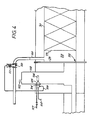
- the level of liquid nitrogen in the freezing tunnel 3 is kept substantially constant.
- liquid nitrogen is introduced through a pipe 100 into the pocket 28 between the baffle plate 27 and a removable plate 29 which extends over substantially the entire cross-sectional area of the cylindrical chamber 30. Part of this liquid is transferred through small slots 101 in plate 29 into a tube 102 which is provided with a vent tube 103 connected to atmosphere.
- transient disturbances causes by product entering the freezing tunnel 3 causes minimal changes in the level in tube 102 which accurately reflects the average liquid level in the vicinity of the ribbon auger 20. It will, of course, be noted that tube 102 is heavily insulated to reduce disturbances which would otherwise be caused by rapid evaporation of the liquid nitrogen in the tube 102.
- the tube 102 contains a level sensing device which is generally identified by reference numeral 104.
- the device 104 comprises a cone 105 to which is pivotally attached a float 106.
- the float 106 rises and falls and this movement is reflected by corresponding movement of a magnet inside cone 105.
- the magnet moves so compressed air supplied from line 107 at about 1.5 bore gauge is directed either through vent 108 or through line 109 to one side of a diaphragm valve 110 which is biased to its closed position by spring 111.
- the liquid level in tube 102 rises the float 106 rises and the magnet moves to direct more compressed air through vent 108.
Landscapes
- Engineering & Computer Science (AREA)
- Mechanical Engineering (AREA)
- Chemical & Material Sciences (AREA)
- Life Sciences & Earth Sciences (AREA)
- General Engineering & Computer Science (AREA)
- Thermal Sciences (AREA)
- Physics & Mathematics (AREA)
- Combustion & Propulsion (AREA)
- Wood Science & Technology (AREA)
- Zoology (AREA)
- Food Science & Technology (AREA)
- Polymers & Plastics (AREA)
- Freezing, Cooling And Drying Of Foods (AREA)
- Devices That Are Associated With Refrigeration Equipment (AREA)
- Meat, Egg Or Seafood Products (AREA)
Claims (12)
Applications Claiming Priority (2)
| Application Number | Priority Date | Filing Date | Title |
|---|---|---|---|
| GB8230972 | 1982-10-29 | ||
| GB08230972A GB2131142B (en) | 1982-10-29 | 1982-10-29 | Food freezing tunnels |
Publications (3)
| Publication Number | Publication Date |
|---|---|
| EP0109210A2 EP0109210A2 (de) | 1984-05-23 |
| EP0109210A3 EP0109210A3 (en) | 1984-09-05 |
| EP0109210B1 true EP0109210B1 (de) | 1986-07-09 |
Family
ID=10533929
Family Applications (1)
| Application Number | Title | Priority Date | Filing Date |
|---|---|---|---|
| EP83306397A Expired EP0109210B1 (de) | 1982-10-29 | 1983-10-21 | Gefriereinrichtung |
Country Status (10)
| Country | Link |
|---|---|
| US (1) | US4499740A (de) |
| EP (1) | EP0109210B1 (de) |
| JP (1) | JPS59107174A (de) |
| KR (1) | KR880001432B1 (de) |
| BR (1) | BR8306124A (de) |
| CA (1) | CA1228240A (de) |
| ES (1) | ES8500717A1 (de) |
| GB (1) | GB2131142B (de) |
| MX (1) | MX156790A (de) |
| ZA (1) | ZA838063B (de) |
Cited By (1)
| Publication number | Priority date | Publication date | Assignee | Title |
|---|---|---|---|---|
| EP4197340A4 (de) * | 2020-07-28 | 2024-07-10 | Mackenna Salinas, Carlos Adolfo | System zur verarbeitung von biomasse oder nahrungsmitteln oder fisch zur optimierung des thermischen energiepotenzials hinsichtlich des volumens einer kühlflüssigkeit |
Families Citing this family (21)
| Publication number | Priority date | Publication date | Assignee | Title |
|---|---|---|---|---|
| US4569204A (en) * | 1985-03-11 | 1986-02-11 | Aga, A.B. | Method and apparatus for simultaneously cooling and conveying a food substance |
| FR2578964B1 (fr) * | 1985-03-12 | 1988-12-09 | Quiri Cie Sa Usines | Surgelateur ou secheur industriel a lit fluidise et a fort pouvoir de retention des fines |
| GB2225846A (en) * | 1988-12-09 | 1990-06-13 | Air Prod & Chem | Tunnel freezer |
| CA1323764C (en) * | 1989-09-29 | 1993-11-02 | Miroslav Tucek | Scrap freezing tunnel |
| DE4017565A1 (de) * | 1990-05-31 | 1991-12-05 | Messer Griesheim Gmbh | Vorrichtung zum gefrieren von schuett- und fliessfaehigen stoffen |
| FR2686965B1 (fr) * | 1992-01-30 | 1998-11-13 | Anhydride Carbonique Ind | Procede et installation pour le refroidissement en continu de produits particulaires. |
| US5295366A (en) * | 1993-01-19 | 1994-03-22 | Gaudencio Lopez | Sealed refrigeration immersion vessel |
| GB2286657A (en) * | 1994-02-14 | 1995-08-23 | Boc Group Plc | Immersion freezer |
| NL1009914C2 (nl) * | 1998-08-21 | 2000-02-22 | Hoek Loos Bv | Werkwijze en inrichting voor het in diepgevroren verpakte toestand brengen van een voedingsmiddel. |
| WO2001046344A1 (en) | 1999-12-21 | 2001-06-28 | Texaco Development Corporation | Apparatus and method for withdrawing and dewatering slag from a gasification system |
| US20060283195A1 (en) * | 2005-06-16 | 2006-12-21 | Uwe Rosenbaum | Process and apparatus for continuous cooling of pumpable material with a liquid cryogen |
| KR100942034B1 (ko) * | 2008-06-11 | 2010-02-11 | 주식회사 탑그린테크 | 식품류의 급속동결을 위한 다층구조의 터널식 동결방법 및그에 사용되는 냉매 |
| US20110311700A1 (en) * | 2009-12-11 | 2011-12-22 | Paul Cyrus Shah | System and method of chilling a food product proximate to and in a food processing device |
| US20130011533A1 (en) | 2010-02-25 | 2013-01-10 | Langley J Barton | Method and Apparatus for Chilled Water Injection |
| CN102338392A (zh) * | 2010-07-21 | 2012-02-01 | 安徽海螺川崎工程有限公司 | 炉渣排出装置 |
| US9089149B2 (en) | 2013-03-15 | 2015-07-28 | Cooling & Applied Technology, Inc. | Poultry chiller with multi-blade long-pitch auger |
| JP6995511B2 (ja) * | 2017-07-03 | 2022-02-04 | 三菱電機株式会社 | 冷蔵庫及び冷蔵庫の温度制御方法 |
| JP7185000B2 (ja) * | 2017-07-03 | 2022-12-06 | 三菱電機株式会社 | 冷蔵庫及び冷蔵庫の温度制御方法 |
| CN107380357B (zh) * | 2017-08-08 | 2023-06-30 | 浙江海洋大学 | 一种船用螺旋式液氮冷冻设备 |
| CN208075418U (zh) * | 2018-03-12 | 2018-11-09 | 江苏诺克诺菲智能机械有限公司 | 隧道灌注式水产品冷冻机 |
| NO20211481A1 (en) * | 2021-12-08 | 2023-06-09 | Mmc First Process As | Exothermic and endothermic processing of fish for storage |
Family Cites Families (15)
| Publication number | Priority date | Publication date | Assignee | Title |
|---|---|---|---|---|
| US2789738A (en) * | 1953-11-24 | 1957-04-23 | Allied Chem & Dye Corp | Screw conveyor |
| US3250086A (en) * | 1959-02-09 | 1966-05-10 | Jr William F Morris | Chilling apparatus |
| US3053519A (en) * | 1961-07-05 | 1962-09-11 | Jack O Chertkof | Proportioning, agitating and pouring device |
| US3413818A (en) * | 1963-12-13 | 1968-12-03 | Fmc Corp | Immersion freezing |
| US3300993A (en) * | 1964-02-25 | 1967-01-31 | Alfred H Schlemmer | Freezing apparatus and method |
| US3298188A (en) * | 1964-04-24 | 1967-01-17 | Air Reduction | Method and apparatus for freezing food products |
| GB1088126A (en) * | 1964-07-02 | 1967-10-25 | Air Reduction | Immersion freezing process |
| US3304732A (en) * | 1965-12-29 | 1967-02-21 | Thermice Corp | Method and apparatus for chilling articles, especially food items |
| US3368363A (en) * | 1966-05-31 | 1968-02-13 | Du Pont | Process for freezing food using liquid refrigerant |
| US3395549A (en) * | 1966-11-16 | 1968-08-06 | Marine Constr & Design Co | Process and apparatus for quick freezing of food bodies |
| CA964921A (en) * | 1971-05-11 | 1975-03-25 | Gordon E. Timbers | Frozen food substance from egg, its production and apparatus therefor |
| GB1409444A (en) * | 1971-10-13 | 1975-10-08 | Lipoma S P | Apparatus for the treatment of solid substances with a volatile liquid |
| US3805538A (en) * | 1972-07-13 | 1974-04-23 | Chemetron Corp | Steady state food freezing process |
| BE788006A (fr) * | 1972-08-25 | 1972-12-18 | Briet Pierre | Vis de transport. |
| DE7721729U1 (de) * | 1977-07-11 | 1977-10-13 | Messer Griesheim Gmbh, 6000 Frankfurt | Vorrichtung zum granulieren und tiefkuehlen von fluessigen und pastoesen massen |
-
1982
- 1982-10-29 GB GB08230972A patent/GB2131142B/en not_active Expired
-
1983
- 1983-10-21 EP EP83306397A patent/EP0109210B1/de not_active Expired
- 1983-10-27 JP JP58200108A patent/JPS59107174A/ja active Pending
- 1983-10-28 CA CA000440010A patent/CA1228240A/en not_active Expired
- 1983-10-28 MX MX199246A patent/MX156790A/es unknown
- 1983-10-28 ZA ZA838063A patent/ZA838063B/xx unknown
- 1983-10-28 ES ES526870A patent/ES8500717A1/es not_active Expired
- 1983-10-28 US US06/546,678 patent/US4499740A/en not_active Expired - Fee Related
- 1983-10-28 KR KR1019830005118A patent/KR880001432B1/ko not_active Expired
- 1983-10-31 BR BR8306124A patent/BR8306124A/pt unknown
Cited By (1)
| Publication number | Priority date | Publication date | Assignee | Title |
|---|---|---|---|---|
| EP4197340A4 (de) * | 2020-07-28 | 2024-07-10 | Mackenna Salinas, Carlos Adolfo | System zur verarbeitung von biomasse oder nahrungsmitteln oder fisch zur optimierung des thermischen energiepotenzials hinsichtlich des volumens einer kühlflüssigkeit |
Also Published As
| Publication number | Publication date |
|---|---|
| GB2131142B (en) | 1986-03-05 |
| ES526870A0 (es) | 1984-11-01 |
| GB2131142A (en) | 1984-06-13 |
| MX156790A (es) | 1988-10-04 |
| KR880001432B1 (ko) | 1988-08-08 |
| ES8500717A1 (es) | 1984-11-01 |
| EP0109210A2 (de) | 1984-05-23 |
| CA1228240A (en) | 1987-10-20 |
| KR840006403A (ko) | 1984-11-29 |
| ZA838063B (en) | 1985-06-26 |
| BR8306124A (pt) | 1984-06-12 |
| JPS59107174A (ja) | 1984-06-21 |
| EP0109210A3 (en) | 1984-09-05 |
| US4499740A (en) | 1985-02-19 |
Similar Documents
| Publication | Publication Date | Title |
|---|---|---|
| US4499740A (en) | Freezer | |
| US4914927A (en) | Method and apparatus for freezing products | |
| JPH06221737A (ja) | 食品を冷凍する装置及び方法 | |
| US4129015A (en) | Ice storage and dispensing bin | |
| JP2977896B2 (ja) | 低温装置 | |
| AU664238B2 (en) | Freezing method and device | |
| US5878582A (en) | Method and apparatus for freezing food products | |
| US4852358A (en) | Cryogenic combination tunnel freezer | |
| US4403479A (en) | Quick freezing system | |
| US5765381A (en) | Multitier crossflow cryogenic freezer and method of use | |
| EP0372354A2 (de) | Gefriertunnel | |
| US3446030A (en) | Method and apparatus for quick freezing individual food items | |
| US9016081B2 (en) | Method and apparatus for cooling foodstuff | |
| US5606861A (en) | Crossflow cryogenic freezer and method of use | |
| US2284270A (en) | Method and apparatus for grading and individually freezing various articles | |
| US5836166A (en) | Cooling apparatus | |
| US2182556A (en) | Method and apparatus for preservation of perishable foodstuffs | |
| US2228998A (en) | Refrigerating apparatus | |
| US4719760A (en) | Method of and apparatus for freezing food | |
| KR0160300B1 (ko) | 식품 냉각장치 | |
| NO315782B1 (no) | Tunnel av typen med endelöse båndtransportörer, for kontinuerlig dypfrysingav n¶ringsmiddelprodukter | |
| US4798614A (en) | Process and device for cooling | |
| US5222363A (en) | Fluidized bed air cooling system | |
| US3498070A (en) | Method and apparatus for quick freezing food products | |
| GB2023789A (en) | Method and apparatus for cooling or freezing |
Legal Events
| Date | Code | Title | Description |
|---|---|---|---|
| PUAI | Public reference made under article 153(3) epc to a published international application that has entered the european phase |
Free format text: ORIGINAL CODE: 0009012 |
|
| AK | Designated contracting states |
Designated state(s): FR NL |
|
| PUAL | Search report despatched |
Free format text: ORIGINAL CODE: 0009013 |
|
| 17P | Request for examination filed |
Effective date: 19840507 |
|
| AK | Designated contracting states |
Designated state(s): FR NL |
|
| GRAA | (expected) grant |
Free format text: ORIGINAL CODE: 0009210 |
|
| AK | Designated contracting states |
Kind code of ref document: B1 Designated state(s): FR NL |
|
| ET | Fr: translation filed | ||
| PLBI | Opposition filed |
Free format text: ORIGINAL CODE: 0009260 |
|
| 26 | Opposition filed |
Opponent name: LINDE AKTIENGESELLSCHAFT, WIESBADEN Effective date: 19870402 |
|
| NLR1 | Nl: opposition has been filed with the epo |
Opponent name: LINDE AKTIENGESELLSCHAFT |
|
| PLBN | Opposition rejected |
Free format text: ORIGINAL CODE: 0009273 |
|
| STAA | Information on the status of an ep patent application or granted ep patent |
Free format text: STATUS: OPPOSITION REJECTED |
|
| 27O | Opposition rejected |
Effective date: 19880904 |
|
| NLR2 | Nl: decision of opposition | ||
| PGFP | Annual fee paid to national office [announced via postgrant information from national office to epo] |
Ref country code: FR Payment date: 19891016 Year of fee payment: 7 |
|
| PGFP | Annual fee paid to national office [announced via postgrant information from national office to epo] |
Ref country code: NL Payment date: 19891031 Year of fee payment: 7 |
|
| PG25 | Lapsed in a contracting state [announced via postgrant information from national office to epo] |
Ref country code: NL Effective date: 19910501 |
|
| NLV4 | Nl: lapsed or anulled due to non-payment of the annual fee | ||
| PG25 | Lapsed in a contracting state [announced via postgrant information from national office to epo] |
Ref country code: FR Effective date: 19910628 |
|
| REG | Reference to a national code |
Ref country code: FR Ref legal event code: ST |