EP0109373A2 - Vorrichtung zum Messen von Urin - Google Patents
Vorrichtung zum Messen von Urin Download PDFInfo
- Publication number
- EP0109373A2 EP0109373A2 EP83850304A EP83850304A EP0109373A2 EP 0109373 A2 EP0109373 A2 EP 0109373A2 EP 83850304 A EP83850304 A EP 83850304A EP 83850304 A EP83850304 A EP 83850304A EP 0109373 A2 EP0109373 A2 EP 0109373A2
- Authority
- EP
- European Patent Office
- Prior art keywords
- tube
- urine
- photocell
- opening
- light source
- Prior art date
- Legal status (The legal status is an assumption and is not a legal conclusion. Google has not performed a legal analysis and makes no representation as to the accuracy of the status listed.)
- Withdrawn
Links
Images
Classifications
-
- A—HUMAN NECESSITIES
- A61—MEDICAL OR VETERINARY SCIENCE; HYGIENE
- A61B—DIAGNOSIS; SURGERY; IDENTIFICATION
- A61B5/00—Measuring for diagnostic purposes; Identification of persons
- A61B5/20—Measuring for diagnostic purposes; Identification of persons for measuring urological functions restricted to the evaluation of the urinary system
- A61B5/201—Assessing renal or kidney functions
-
- A—HUMAN NECESSITIES
- A61—MEDICAL OR VETERINARY SCIENCE; HYGIENE
- A61B—DIAGNOSIS; SURGERY; IDENTIFICATION
- A61B5/00—Measuring for diagnostic purposes; Identification of persons
- A61B5/20—Measuring for diagnostic purposes; Identification of persons for measuring urological functions restricted to the evaluation of the urinary system
- A61B5/207—Sensing devices adapted to collect urine
- A61B5/208—Sensing devices adapted to collect urine adapted to determine urine quantity, e.g. flow, volume
-
- G—PHYSICS
- G01—MEASURING; TESTING
- G01F—MEASURING VOLUME, VOLUME FLOW, MASS FLOW OR LIQUID LEVEL; METERING BY VOLUME
- G01F3/00—Measuring the volume flow of fluids or fluent solid material wherein the fluid passes through the meter in successive and more or less isolated quantities, the meter being driven by the flow
- G01F3/36—Measuring the volume flow of fluids or fluent solid material wherein the fluid passes through the meter in successive and more or less isolated quantities, the meter being driven by the flow with stationary measuring chambers having constant volume during measurement
- G01F3/38—Measuring the volume flow of fluids or fluent solid material wherein the fluid passes through the meter in successive and more or less isolated quantities, the meter being driven by the flow with stationary measuring chambers having constant volume during measurement having only one measuring chamber
Definitions
- the present invention relates to a device for measuring urine, particularly for measuring the urine excreted by a catheri- zed patient.
- the object of the present invention is to obtain a possibility to measure small quantities of urine excreted by a patient, whereby the measurement shall be carried out in a safe way and for the caretaking personal in a simple and rational way.
- the staff has therby to measure the flow per time unit "with the clock in the hand", whereby the time unit can be one or some minutes up to some hours dependent on the condition of the patient.
- the urine meter shall thereby, at every measurement or in each case from time to time be emptied, which is done by opening some bottom valves or by turning over the urine meter so that the urine flows down into a larger collecting container, most often a so called urine bag.
- This system has mow turned out to be most unsatisfac- toryas it calls for an intense attention by the staff.
- the staff has to come up to the patient's bed and note the amount of urine excreted, relatively often, and in situation of crisis, very often.
- Further valves shall be opened at emptying or the measuring beaker be turned over, which makes an extra action, and particularly in the latter case is a risk in that connecting tubes loosen with the accompanying risk for infections to and fro the environment.
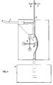
- Fig 1, 1 denotes a tube connected to a catheter (not shown), which tube; in turn, is connected in its other end with a tube 2, suitably what is known as a T-tube, having a long superposed part, and whereby the T-tube is rotated 90°.
- the tube 2 can also be described as a vertically arranged tube having a connector in its side.
- the tube 2 is made of a translucent material, such as glass or glass clear polymer.
- the tube 2 is connected to a flexible tube 3 with its downwardly turned part, which flexible tube 3 is mounted in a peristaltic pump 4 and further connected to a urine collecting bag 5 of a type known per se.
- a photocell 6, and a light source 7, respectively, are arranged on each side of the tube 2, on the upper part thereof.
- the peristaltic pump 4 is of such a construction that it rotates a certain number of revolutions or part of a revolution, all in accordance with the basic adjustment thereof, when it receives a driving signal.
- the device functions so that an amount of urine passes out through the urine catheter and into the tube 1, whereafter it passes into the tube 2.
- the photocell 6 gives an electrical signal which starts the driving motor of the peristaltic pump 4, whereby this goes for example 1/4 of a revolution, or I of a revolution, if so adjusted, whereby a certain, exact amount of urine is pumped out and through the flexible tube 3 to the urine bag 5.
- the photocell 6 will now receive light and the driving of the peristaltic pump is stopped; to be started again as soon as the light beam to teh photocell 6 is broken.
- the number of 1/4-revolutions or I-revolutions which the pump makes can thereby automatically be registered from a set point of time, a zero-point, and thereby the volume of urine excreted can be carefully determined.
- the peristaltic pump 4 also presses so hard on the tube 3 that no leakage occurs downwardly behind the pressing roll 8 of the peristaltic pump.
- the revolutions of the peristaltic pump 4 can be registered by a computer unit (not shown), which can show the number of revolutions on a printer or a display after the zero-point, the number of revolutions during a first 10-minutes period, during a later 10-minutes period, show volumes during certain time periods, accumulated volume and such other suitable and wanted information providing values.
- the time point for each revolution of the peristaltic pump can thus be registered and values obtained can be integrated and collected in any suitable way.
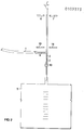
- a tube 1 is shown, which in its one end is connected to a urine catheter and in its other end is connected to a vertically arranged tube 2 having a side connector 9, whereby connection has been made to said connector 9.
- the tube 2 is downwardly connected by means of a tube 3 to a urine collecting bag 5.
- the tube 3 is provided with a magnetic valve 10, which works by clamping the tube 3 against a counter part 11 by means of a jaw 12 actuated by a magnet.
- On each side of the upper part of the tube 2 are an upper photocell 6, and an upper light source 7, respectively, and and a lower photocell 13 and a lower light source 14, respectively, arranged.
- This embodiment functions so that the magnetic valve 10 normally closes the tube 3, urine flows through the tube 1 and fills the tube 2.
- the urine level reaches the upper photocell 6 the light beam directed thereto is broken, a signal is transmitted to the magnetic valve 10, which opens and urine flows downwardly to the urine bag 5.
- the urine level reaches the level for the lower photocell 13 this obtains a light beam from its light source 14, whereby a signal is transmitted to the magnetic valve 10, which closes the tube 3.
- a volume of urine corresponding to the volume of the tube 2 between the photocells 6 and 13 has passed down to the bag 5, as well as a minor amount directly from the tube 1 via the connector 9 and downwardly.
- a guarding alarm can also be introduced quite simple. so that at a non-reaching of a given minimum volume an alarm is given to a centre being continously attended to as is the case on an intense care unit.
- the computer use also means that values can be easily stored and be brought forward if so requested, even a long time after the patient has left the hospital.
- the light used in the photocell/light source can be of a visible or non-visible wave-length. It can for some reason be necessary to utilize non-visible light, if one fears that strong light may affect the photocell.
- the photocell can however, be considerably protected against infalling light by being placed in a cylinder, whereby only the light being directed from the light source affects it.
- the pump 4 above shall preferably be provided with a step- motor which drives a given number of steps when it obtains a signal. These steps can then easily be registered. This type of motor will also provide for a very accurate measur- ment.
- the present device has shown to provide very accurate measurements in the range from 2- 18000 ml per 24 hours, and can thus be used in all types of situations.
Landscapes
- Health & Medical Sciences (AREA)
- Life Sciences & Earth Sciences (AREA)
- Physics & Mathematics (AREA)
- Medical Informatics (AREA)
- Surgery (AREA)
- Urology & Nephrology (AREA)
- Veterinary Medicine (AREA)
- Biophysics (AREA)
- Pathology (AREA)
- Engineering & Computer Science (AREA)
- Biomedical Technology (AREA)
- Heart & Thoracic Surgery (AREA)
- Public Health (AREA)
- Molecular Biology (AREA)
- Physiology (AREA)
- Animal Behavior & Ethology (AREA)
- General Health & Medical Sciences (AREA)
- Fluid Mechanics (AREA)
- General Physics & Mathematics (AREA)
- Measurement Of The Respiration, Hearing Ability, Form, And Blood Characteristics Of Living Organisms (AREA)
- Investigating Or Analysing Materials By Optical Means (AREA)
- Investigating Or Analysing Biological Materials (AREA)
- Measuring Pulse, Heart Rate, Blood Pressure Or Blood Flow (AREA)
- Electric Clocks (AREA)
Applications Claiming Priority (2)
| Application Number | Priority Date | Filing Date | Title |
|---|---|---|---|
| SE8206430 | 1982-11-12 | ||
| SE8206430A SE8206430L (sv) | 1982-11-12 | 1982-11-12 | Anordning for urinmetning |
Publications (2)
| Publication Number | Publication Date |
|---|---|
| EP0109373A2 true EP0109373A2 (de) | 1984-05-23 |
| EP0109373A3 EP0109373A3 (de) | 1985-12-11 |
Family
ID=20348556
Family Applications (1)
| Application Number | Title | Priority Date | Filing Date |
|---|---|---|---|
| EP83850304A Withdrawn EP0109373A3 (de) | 1982-11-12 | 1983-11-11 | Vorrichtung zum Messen von Urin |
Country Status (6)
| Country | Link |
|---|---|
| EP (1) | EP0109373A3 (de) |
| JP (1) | JPS59502012A (de) |
| FI (1) | FI842783A0 (de) |
| NO (1) | NO842808L (de) |
| SE (1) | SE8206430L (de) |
| WO (1) | WO1984001889A1 (de) |
Cited By (6)
| Publication number | Priority date | Publication date | Assignee | Title |
|---|---|---|---|---|
| DE4338687C1 (de) * | 1993-11-12 | 1995-07-06 | Fresenius Ag | Urinmeßgerät und Verfahren zum Ermitteln der Dichte von Urin |
| EP1593345A1 (de) * | 2004-05-07 | 2005-11-09 | Transmed Medizintechnik GmbH & Co. KG | Vorrichtung zur automatischen Überwachung des Flusses einer Flüssigkeit, insbesondere Urin |
| CN109199415A (zh) * | 2017-07-02 | 2019-01-15 | 郑奕智 | 体液排出量监测装置及方法 |
| US10362780B2 (en) | 2011-11-10 | 2019-07-30 | Organox Limited | Oxygen supply for organ perfusion systems |
| US11540508B2 (en) | 2011-11-10 | 2023-01-03 | Organox Limited | Organ perfusion systems |
| US11957124B2 (en) | 2011-11-10 | 2024-04-16 | Organox Limited | Organ perfusion systems |
Families Citing this family (2)
| Publication number | Priority date | Publication date | Assignee | Title |
|---|---|---|---|---|
| CN103735279B (zh) * | 2013-12-12 | 2015-05-06 | 科迈(常州)电子有限公司 | 尿液计量仪旋转固定机构 |
| KR101831101B1 (ko) * | 2017-01-02 | 2018-02-22 | 인제대학교 산학협력단 | 의료용 소변 채집 장치 |
Family Cites Families (6)
| Publication number | Priority date | Publication date | Assignee | Title |
|---|---|---|---|---|
| US3019649A (en) * | 1957-08-16 | 1962-02-06 | Phillips Petroleum Co | Metering system for liquids |
| US3818895A (en) * | 1971-11-01 | 1974-06-25 | J Stewart | Oligaemic shock assessment apparatus |
| US3919455A (en) * | 1972-10-20 | 1975-11-11 | Hoffmann La Roche | Apparatus for the measurement of the volume and flow rate of liquids |
| DE2547705A1 (de) * | 1975-10-24 | 1977-05-05 | Michael Dr Med Polonius | Geraet zur portionsweisen messung physiologischer fluessigkeiten |
| GB1570390A (en) * | 1976-12-09 | 1980-07-02 | Nat Res Dev | Device for measuring liquid flow |
| US4532936A (en) * | 1981-08-21 | 1985-08-06 | Leveen Eric G | Automatic urine flow meter |
-
1982
- 1982-11-12 SE SE8206430A patent/SE8206430L/xx not_active Application Discontinuation
-
1983
- 1983-11-11 JP JP58503661A patent/JPS59502012A/ja active Pending
- 1983-11-11 EP EP83850304A patent/EP0109373A3/de not_active Withdrawn
- 1983-11-11 WO PCT/SE1983/000394 patent/WO1984001889A1/en not_active Ceased
- 1983-11-11 FI FI842783A patent/FI842783A0/fi not_active Application Discontinuation
-
1984
- 1984-07-10 NO NO842808A patent/NO842808L/no unknown
Cited By (6)
| Publication number | Priority date | Publication date | Assignee | Title |
|---|---|---|---|---|
| DE4338687C1 (de) * | 1993-11-12 | 1995-07-06 | Fresenius Ag | Urinmeßgerät und Verfahren zum Ermitteln der Dichte von Urin |
| EP1593345A1 (de) * | 2004-05-07 | 2005-11-09 | Transmed Medizintechnik GmbH & Co. KG | Vorrichtung zur automatischen Überwachung des Flusses einer Flüssigkeit, insbesondere Urin |
| US10362780B2 (en) | 2011-11-10 | 2019-07-30 | Organox Limited | Oxygen supply for organ perfusion systems |
| US11540508B2 (en) | 2011-11-10 | 2023-01-03 | Organox Limited | Organ perfusion systems |
| US11957124B2 (en) | 2011-11-10 | 2024-04-16 | Organox Limited | Organ perfusion systems |
| CN109199415A (zh) * | 2017-07-02 | 2019-01-15 | 郑奕智 | 体液排出量监测装置及方法 |
Also Published As
| Publication number | Publication date |
|---|---|
| EP0109373A3 (de) | 1985-12-11 |
| WO1984001889A1 (en) | 1984-05-24 |
| FI842783L (fi) | 1984-07-11 |
| SE8206430D0 (sv) | 1982-11-12 |
| FI842783A7 (fi) | 1984-07-11 |
| SE8206430L (sv) | 1984-05-13 |
| JPS59502012A (ja) | 1984-12-06 |
| NO842808L (no) | 1984-07-10 |
| FI842783A0 (fi) | 1984-07-11 |
Similar Documents
| Publication | Publication Date | Title |
|---|---|---|
| DE69631068T2 (de) | System zur regelung der flüssigkeitsrückhaltung | |
| EP0200004B1 (de) | Elektronisches Verfahren für Drainage | |
| US4343316A (en) | Electronic urine flow monitor | |
| US6238366B1 (en) | System for fluid retention management | |
| US4606826A (en) | Apparatus for controlling ultrafiltration and method for the same | |
| US5769087A (en) | Urine measurement apparatus and method for the determination of the density of urine | |
| US4532936A (en) | Automatic urine flow meter | |
| US7207966B2 (en) | System for fluid retention management | |
| EP0007618B1 (de) | Tropfenmessgerät | |
| US5176148A (en) | Device for measuring the urine flow (uroflow) of patient | |
| US4324663A (en) | Method and apparatus for regulating haemodialysis conditions | |
| US4780418A (en) | Method and apparatus for measuring the aggregation of blood platelets or the coagulation of blood | |
| US4889635A (en) | Method and apparatus for controlling the quantities of liquid circulating in the dialysis liquid circuit of an artificial kidney | |
| US4859319A (en) | Device for measuring the quantity of ultrafiltrate eliminated during a dialysis treatment | |
| JP2002535607A (ja) | 低流量用小滴カウンタ | |
| JPS63503116A (ja) | 静脈内ラインバルブシステム | |
| WO1984001889A1 (en) | Device for measuring urine | |
| CN104939846A (zh) | 一种动态尿液计量仪 | |
| AU2262083A (en) | Device for measuring urine | |
| CN109200391A (zh) | 一种输液监控终端 | |
| RU2036607C1 (ru) | Устройство для определения степени негерметичности легкого или культи бронха | |
| IE58296B1 (en) | Electronic drainage system | |
| JPH0226561A (ja) | 採血重量を測定する採血装置 | |
| JPH06307900A (ja) | 医用流量計 |
Legal Events
| Date | Code | Title | Description |
|---|---|---|---|
| PUAI | Public reference made under article 153(3) epc to a published international application that has entered the european phase |
Free format text: ORIGINAL CODE: 0009012 |
|
| AK | Designated contracting states |
Designated state(s): AT BE CH DE FR GB IT LI LU NL SE |
|
| 17P | Request for examination filed |
Effective date: 19841120 |
|
| PUAL | Search report despatched |
Free format text: ORIGINAL CODE: 0009013 |
|
| AK | Designated contracting states |
Designated state(s): AT BE CH DE FR GB IT LI LU NL SE |
|
| STAA | Information on the status of an ep patent application or granted ep patent |
Free format text: STATUS: THE APPLICATION IS DEEMED TO BE WITHDRAWN |
|
| 18D | Application deemed to be withdrawn |
Effective date: 19860612 |
|
| RIN1 | Information on inventor provided before grant (corrected) |
Inventor name: EKBLADH, FRED VAGE GUNNAR Inventor name: TILLANDER, HANS |